Pacbrake HP10121 KIT User manual

HP10121 KIT
Dodge Ram 4500/5500 Chassis Cab 2WD/4WD*
Sterling Bullet 4500/5500 Chassis Cab 2WD/4WD*
* See application guide for proper fitment.
Use the most advanced air springs on the market to eliminate your vehicle’s sag, sway
and bottoming out. Pacbrake air suspension levels your truck’s stance while providing
added support for an overall smooth and safe ride.

Pacbrake is a registered trademark of Pacbrake Co. 2
HP10121 AMP AIR SUSPENSION KIT L5934
L5934.REV10_16.07.2018
REQUIRED TOOLS
•7/16", 1/2", 9/16" open end or box wrenches
•13mm, 15mm, 16mm and 21mm open
end wrenches
•Adjustable Wrench
•Torque Wrench
•9/16",
1/2"deep well sockets
•Heavy Duty Drill
•5/16" Drill Bits (very sharp)
•Hose Cutter, Razor Blade or Sharp Knife
•Pipe Thread Sealant
•Air Compressor /Compressed Air Source
•Hoist or Floor Jack
•Safety Stands
•Safety Glasses
•Spray Bottle with Dish Soap/Water
KIT CONTENTS
AAir Springs (2) HP10068
BLower Bracket (2) HP0099
CUpper Frame Bracket (2) HP1147
Upper Air Spring Bracket (2) HP1148
D90° Fitting (2) HP1245
EHeat Shield (1) HP0012
F 3/8" Nylock Nut (12) HP1000
H3/8" Large Flat Washer (16) C18006
I3/8" Lock Washer (4) C18007
JGear Clamp #48-102 (2) HP1001
K3/8" NF x 7/8" Capscrews (8) HP1002
L Axle Strap (2) HP0102
M3/8"-16 x 5 Carriage Bolt (4) HP1022
Roll Plate (4) HP10069
5/16" Nylock Nut (1) C11943
3/8" - 16 x 11/4" Carriage Bolt (4) HP1149
QSway bar brackets (4) HP0100/HP0101
RM10 X 1.5 X 35mm bolt (8) HP1134
S3/8" - 16 x 13/4" bolt (4) HP1227
T3/8" Small Flat Washer (4) C653
UAir Line/Valve Assembly HP1344
VTie Strap (6) C11618
Make sure all
the items shown
in the photo are
provided in your
kit before starting
the installation.
A
B
C
D
E
F
G
H
I
J
K
L
M
N
O
P
CAUTION: This kit includes “push to connect OR barbed” airline ttings. They require the end of the
airline to be round, square and cleanly cut to ensure the internal seal will not leak. The airline must
only be cut with a sharp razor knife or hose cutter.
A A
B
B
C C
DD
E
F
GH
I
J
K
LL
M
N
N
N
N
O
P
Q Q
QQ
RS
T
U
V

Pacbrake is a registered trademark of Pacbrake Co. 3
HP10121 AMP AIR SUSPENSION KIT L5934
L5934.REV10_16.07.2018
Thank you and congratulations on the purchase of an AMP air suspension kit.
IMPORTANT:
The air suspension kit will not increase the GVWR (gross vehicle weight rating), as this is determined by the
axle rating. Do not exceed the maximum capacity listed by the vehicle manufacturer.
Before starting, ensure the application information is correct for the make, model and year of the vehicle you
are installing it on. Please read the entire installation manual prior to starting the installation to ensure you can
complete it once started.
Pacbrake recommends using a good quality anti-seize on all fasteners, this will reduce the chances of corrosion
of the fasteners, and help facilitate removal if required at a later date.
PREASSEMBLY OF THE AIR SPRINGS
1THE UPPER ROLL PLATE
Place the upper roll plate (with the rounded side towards the air spring)
on the top of the air spring (top being the end with the air inlet port). Apply
thread sealant or Teon tape to the threads of the tting provided. Install the tting.
2THE UPPER BRACKET
Place the upper air spring mounting bracket on top of the air spring and roll plate.
The upper air spring mounting bracket is identied by the two 3/8" holes next to
the air tting cut out. Using 2 - 3/8" NF x 7/8" capscrews provided, fasten the bracket
to the air spring. Torque both capscrews to 20 ft-lbs, 27 N•m.
3THE LOWER PLATE & BRACKET
Insert the two 5" long carriage bolts provided into the two elongated holes in the
lower bracket. Place the roll plate on the air spring with the rolled side towards the
air spring. Place the lower bracket on the air spring with the two carriage bolts on the
opposite side to the air port. Install the two 3/8" NF capscrews lock and small at
washers, do not tighten fully. Ensure the air tting is on the opposite side of the two
carriage bolts.
Repeat steps 1 - 3 on the other air spring
The lower bracket mounting holes are slotted and need to be adjusted on the air
spring before tightening the 3/8" NF fasteners.
Position one air spring assembly with the carriage bolts to your left. PULL the
lower bracket towards you to the end of the slotted holes. Tighten the capscrews
to 20 ft-lbs, 27 N•m. This will now become the passenger side air spring.
Position the other air spring assembly with the carriage bolts to your left. PUSH
the lower bracket away from you to the end of the slotted holes. Tighten the
capscrews to 20 ft-lbs, 27 N•m. This will now become the driver side air spring.
STEP 1
STEP 2
STEP 3

Pacbrake is a registered trademark of Pacbrake Co. 4
HP10121 AMP AIR SUSPENSION KIT L5934
L5934.REV10_16.07.2018
4INSTALLATION ON THE VEHICLE
Raise the vehicle enough for a comfortable working height with a oor jack
and support the axle with jack stands.
Remove the jounce bumpers on both sides.
5Remove both lower shock absorber fasteners. Retain nuts and bolts for reuse.
Remove the 2 nuts holding the sway bar up to the axle tube bracket on both
sides. Allow the sway bar to swing down towards the ground. Discard the factory
sway bar bolts and retain the nuts for re-use.
6The passenger side shock absorber mounting bracket has an emergency brake
cable support bracket that needs to be removed.
7The top of the rear end housing has a bolt supporting the cable to the top of the
rear end housing. Remove the bolt and bracket and re-install the bolt.
8On the passenger side only, compress the shock absorber to allow the e-brake
cable to be moved to the forward side of the shock absorber.
STEP 4
STEP 6
STEP 5
STEP 8
STEP 7

Pacbrake is a registered trademark of Pacbrake Co. 5
HP10121 AMP AIR SUSPENSION KIT L5934
L5934.REV10_16.07.2018
9Locate the ABS sensor and harness on the topside front of the rear end housing.
This harness is supported on a stud with a white plastic fastener.
10 Remove the fastener. Install the e-brake cable bracket, removed in step 9, to this
stud. A 5/16" nut is provided to secure the bracket. Re-install the plastic fastener
on the stud.
11 ATTACH THE UPPER BRACKET
Using the M10 x 35 capscrews provided, fasten the upper air spring mounting
bracket to the frame as shown in the photo. Torque the capscrews to 30 ft-lbs,
40 N•m. The upper brackets must be installed to the jounce bracket with the air
inlet tting cutout and rectangular holes in the bracket facing towards the center
of the vehicle.
12 INSTALLING THE AIR SPRING
Insert the air spring between the jounce bumper mounting plate and the axle
tube. Some vehicles may require the frame to be jacked up slightly to attain
clearance.
NOTE: Air ttings must be positioned towards the center of the vehicle. The
outer rear carriage bolts may be installed now and must be between the brake
line and the axle tube. On the drivers side, both rear carriage bolts must be in
between the brake line and the axle tube. Passengers side is shown in photo.
Loosely install two of the 1¼" long carriage bolts up from the bottom through both
the upper mounting plates. Install the large at washers and nylock nuts provided.
Loosely install the axle straps to the carriage bolts using the large at washers and
nylock nuts provided.
STEP 12
STEP 11
STEP 9
STEP 10

Pacbrake is a registered trademark of Pacbrake Co. 6
HP10121 AMP AIR SUSPENSION KIT L5934
L5934.REV10_16.07.2018
16 CHECK THE CLEARANCE
Ensure adequate clearance exists between the brake lines and the carriage
bolts. The brake line must not touch the carriage bolts. Adjust to attain clearance
if necessary. Once correct alignment of the air spring is attained:
Tighten the four sway bar bolts to 45 ft-lbs, 61 N•m.
Tighten the two 1¼" carriage bolts of the top brackets to 20 ft-lbs, 27 N•m.
Tighten the two axle strap carriage nuts to 20 ft-lbs, 27 N•m.
Tighten the two support bracket to upper bracket fasteners to 20 ft-lbs, 27 N•m.
Repeat on the other air spring.
Re-install and tighten both lower shock absorber fasteners.
Torque to 100 ft-lbs, 135 N•m.
17 INSTALL THE HEAT SHIELD
Bend the two center tabs of the heat shield supplied for fastening to the
exhaust pipe as shown. Attach the heat shield with the gear clamps supplied
to the exhaust pipe to protect the air spring.
STEP 17
13 Using the M10 x 35 capscrews provided, insert one capscrew into each of the
lower support brackets as shown in the photo.
Insert the lower end of the support brackets with bolts into the axle tube sway
bar brackets. Lift the sway bar up and loosely install the original nuts.
14 Loosely install the 3/8- 16 x 1 ¾" bolts with large at washers and nylock nut into
each of the lower air spring brackets to the support brackets.
Install the axle straps onto the 5" long carriage bolts. Loosely install the large at
washers and nylock nuts provided.
15 ADJUST THE AIR SPRING
Adjust the air spring assembly to the upper bracket by moving the lower bracket
on the axle tube to ensure the air spring is correctly aligned (as shown in the
diagram below).
STEP 13
STEP 14
STEP 15
INCORRECT CORRECT
REAR
SUPPORT
BRACKET
FRONT
SUPPORT
BRACKET

Pacbrake is a registered trademark of Pacbrake Co. 7
HP10121 AMP AIR SUSPENSION KIT L5934
L5934.REV10_16.07.2018
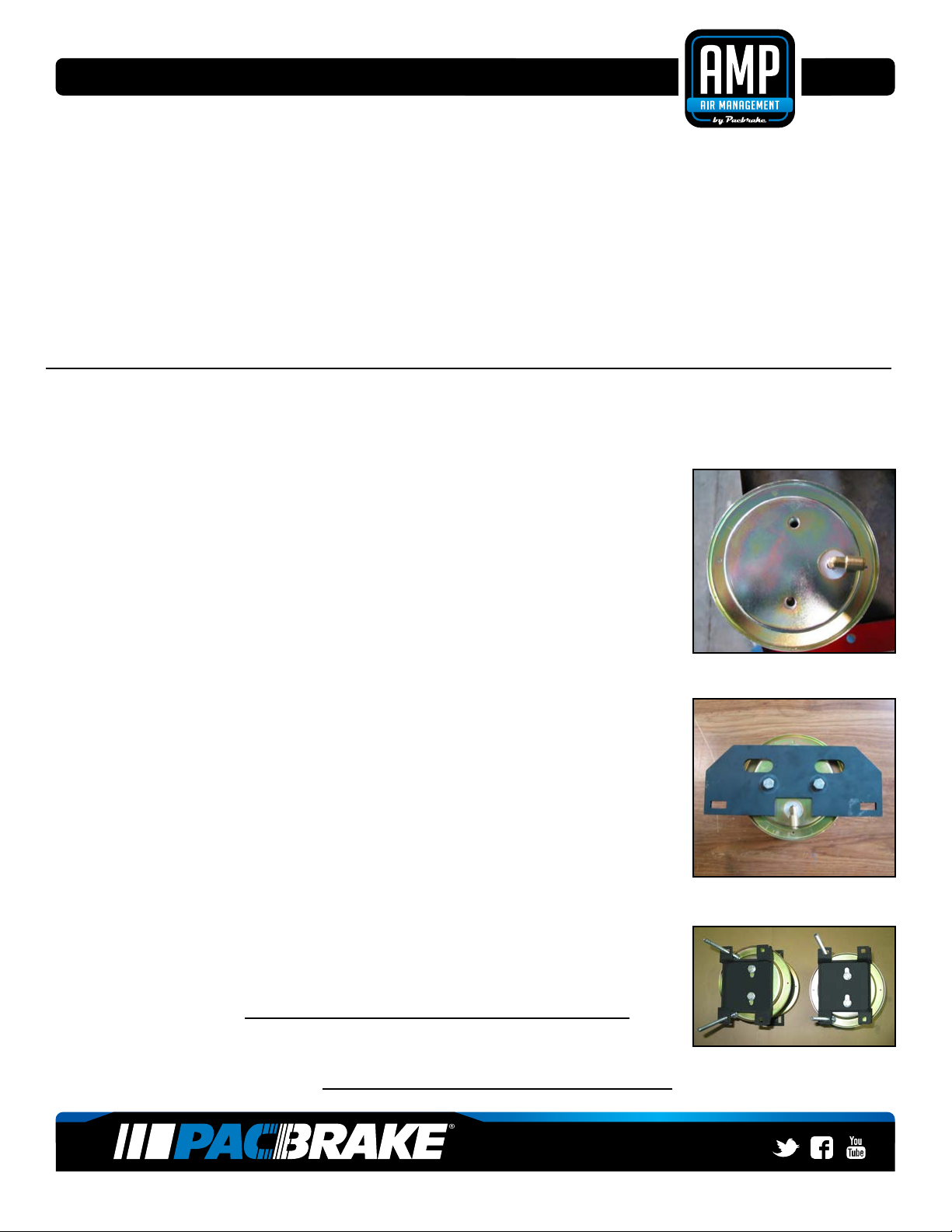
18 AIRLINE INSTALLATION
Provided in the basic air spring kit are two ll valves, the most common place to
install them is to replace the license plate fasteners with the ll valves. Alternatively,
two holes can be drilled in a convenient location. Install one airline provided, route
the nylon hose to an air spring tting, cut the hose and connect to the air spring
tting. Repeat with the other ll valve. Secure airlines with the tie-straps provided
away from moving items and heat sources.
If an in cab ination kit is being installed, follow the instructions provided with it.
NOTE: This kit contains push to connect ttings, using scissors or wire cutters to cut the nylon airline will distort the
line and cause the connection to leak. THE AIRLINE MUST BE CUT OFF SQUARELY WITH A SHARP RAZOR
KNIFE. Moisten the end of the airline prior to inserting it into the tting and push it in until it stops.
IMPORTANT!
Double check all the fasteners are torques to specication
19 LEAK CHECK
Inate both the air springs to 90 PSI. Use a dish soap and water mixture on all
airline connections to detect air leaks. Repair as necessary and retest. Inate
your air springs to a pre-determined value, then the following day recheck the
pressure. If one or both the air springs have lost pressure, a leak is present.
The leak must be repaired, then retest until no leaks exist.
SPECIAL NOTE:
Retorque all the fasteners after the rst 500 miles of driving.
OPTIONAL ACCESSORIES
Pacbrake offers an optional dual needle air gauge to monitor the pressure in each air spring from the vehicles
cab. Pacbrake offers a full line of air compressors, air tanks and solenoids to control your air spring system.
OPERATING YOUR VEHICLE WITH PACBRAKE AIR SUSPENSION
Air springs have minimum and maximum pressure requirements, never operate your vehicle with less then
10 PSI in the air spring and never inate the air springs over 100 PSI, damage to the air springs will result.
Check the air pressure in the air springs daily for the rst couple of days to ensure a leak does not develop.
The air springs are designed to maintain the vehicles stock ride height with a load. Do not use the air springs
as a means to lift the vehicle with no load, a rough ride will result.
SERVICING YOUR VEHICLE WITH PACBRAKE AIR SUSPENSION
When lifting the vehicle with a oor jack or hoist on the frame never allow the air spring to limit the travel of the
axle, try to always jack the vehicle on the axle. Suspending the axle with the air spring limiting the axle travel will
damage the air spring and void the air spring warranty.
WARRANTY
To be eligible for warranty, owner must submit their warranty card or register online within 30 days of purchase
date. NOTE: The owners warranty will be void if air springs run with less than the minimum of 10PSI
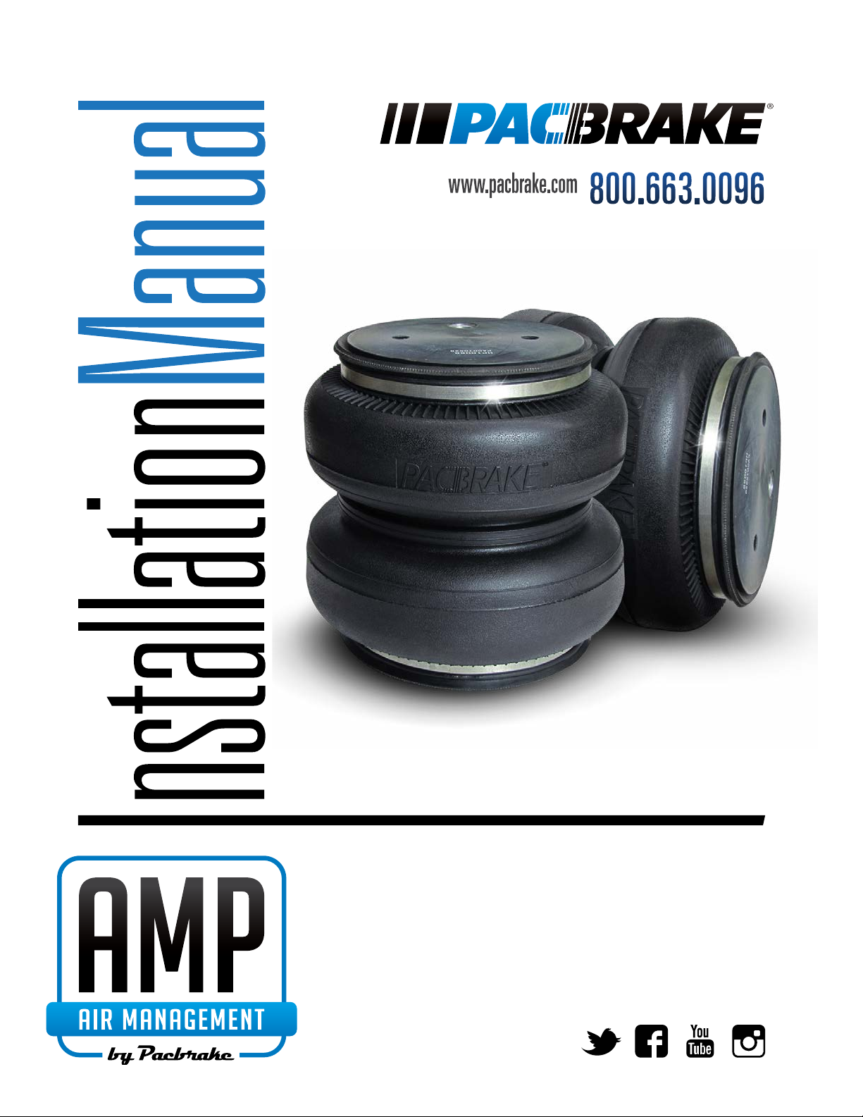
STEP 18
STEP 19
Table of contents
Other Pacbrake Automobile Accessories manuals
Popular Automobile Accessories manuals by other brands

Calearo
Calearo 7677950 installation instructions

Cruz
Cruz Alu Cargo R Assembly instructions

ULTIMATE SPEED
ULTIMATE SPEED 274817 Instructions for use and safety guidelines

LXE
LXE VX7 reference guide

Mont Blanc
Mont Blanc RoofBar Flex 3 BU1 Fitting instructions

Veigel
Veigel BLF00006 Installation and operating instructions