Paccar DAF POWERCHOICE 360X User manual

A PACCAR COMPANY DRIVEN BY QUALITY
POWERCHOICE 360X CABINET
Installation manual

Copyrights
All rights to copyrights, registered trademarks, and
trademarks reside with their respective owners.
Copyright © 2022 PACCAR/Heliox
Notice
This document contains information about one or more
PACCAR/Heliox products and may include a description of or
a reference to one or more standards that may be generally
relevant to the products. The presence of any such
description of a standard or reference to a standard is not a
representation that all of the PACCAR products referenced in
this document support all of the features of the described or
referenced standard. In order to determine the specific
features supported by a particular PACCAR product,
the reader should consult the product specifications for that
particular product.
PACCAR/Heliox may have one or more patents or pending
patent applications protecting the intellectual property in the
PACCAR products described in this document.
The information in this document is subject to change without
notice and should not be construed as a commitment by
PACCAR. PACCAR assumes no responsibility for any errors
that may appear in this document. In no event shall PACCAR
be liable for direct, indirect, special, incidental or
consequential damages of any nature or kind arising from the
use of this document, nor shall PACCAR be liable for
incidental or consequential damages arising from use of any
software or hardware described in this document.
This document and parts thereof must not be reproduced or
copied without written permission from PACCAR/Heliox and
the contents thereof must not be imparted to a third party nor
used for any unauthorized purpose.

Contents
1Preface
1.1
1.1.1
1.1.2
1.2
About the document
Structure of this document
How to use the documentation
Target groups
4
4
4
4
4
2Introduction
2.1
2.2
2.2.1
2.2.2
2.2.3
Site layout considerations
Floorplan
Block configuration
Line configuration
Cable gland plate
5
6
7
8
8
9
3Civil work
3.1
3.2
The foundation
Ventilation
10
11
12
4Mechanical installation
4.1
4.2
4.3
Preparation
Use a forklift to transport the charger
Remove the charger cabinet from the pallet
13
14
14
15
5Electrical installation
5.1
5.1.1
5.1.2
5.1.3
5.2
5.3
5.4
5.4.1
5.4.2
5.4.3
5.4.4
5.5
5.6
Electrical power connection
Ac configuration
Grounding instructions
Preparation
Install the cable lugs and the shrink sleeves
Connect the ac power supply cables
Connect the output connections
Output terminal connections
Interconnection between cabinets
Output terminal wiring
Dc-connections
After installation checks
Evse preconditioning
16
16
17
17
17
17
18
18
19
20
20
21
21
22

1. Preface
About the document 1.1
This document is part of the technical handbook which is an integral part of the Electric Vehicle
Supply Equipment (EVSE), cabinet of the PowerChoice 360X.
This section gives the requirements and instructions for the installation of the Electric Vehicle
Supply Equipment (EVSE), the PowerChoice 360X.
The information given in this document is meant for use by the authorized persons who are
involved with the planning, supervision and execution of the given tasks. These tasks are, but not
limited to, the handling, transport and storage and the installation.
For the execution, different skills and authorizations are required. For generic information, refer to
the introduction of this technical handbook.
Work involved with the EVSE always calls for the safe work procedures with and in the vicinity of
electrical installations. Refer to the local authorities for the rules and regulations that apply and
prevail.
Target groups
1.2
4
Structure of this document
How to use the documentation
1.1.1
1.1.2
This document gives a descriptive summary of the EVSE. Aim of the description is to give a better
understanding of the requirements and the EVSE operation
For easy access to the information, this document is divided into chapters.
The chapters are:
•the preface, to give an introduction to the content and the use of the document;
•the civil work, to detail the work to be done;
•the mechanical installation, to detail the lifting and installation work to be done;
•the electrical installation, to detail the electrical work to be done before commissioning can
start.
This document is part of the technical handbook which is an integral part of the Electric Vehicle
Supply Equipment (EVSE), the PowerChoice 360X.
This document gives the requirements and instructions for the installation of the Electric Vehicle
Supply Equipment (EVSE), the PowerChoice 360X.

2. Introduction
The installation of the EVSE requires administrative work to obtain the required permits as well as work
to prepare for the cables, supply, and the foundation of the EVSE. Contact your local representative to
obtain the necessary permits.
For locations where the EVSE is exposed to direct sunlight and high ambient temperatures for most of
the day, it is recommended to install protection from direct sunlight.
For locations where the EVSE is exposed to the possibility for collisions with vehicles, consider the
installation of collision prevention equipment.
After completion of the supply and civil work, the EVSE is installed mechanically onto the foundation.
When the mechanical work is completed the EVSE is electrically connected and commissioned.
Summarized the civil and construction work requires:
•The physical installation of the foundation and the EVSE cabinet;
•The installation of (underground) AC cable and conduits between the EVSE and the AC power
supply station;
•The installation of the upstream transformer and switchgear;
•The installation of required earth electrode(s);
•The electrical installation and commissioning of the EVSE;
•If applicable, the installation of a network connection for remote communication;
•The construction and lining of a parking place (charging place) for the EV;
•As applicable, any work related to the road signs and markings.
As covered in earlier sections of this handbook, this product has several deployment configurations.
These deployment configurations include, but aren't limited to, variations of:
1. A standalone unit with attached CCS cable
2. This base unit with a single or several remote CCS cable outlets
(outlet detail covered in a separate dedicated handbook).
3. This base unit with a single or several remote inverted pantograph outlets
(outlet detail covered in a separate dedicated handbook).
4. This base unit with a combination of remote CCS cable outlets and inverted pantograph outlets.
5

Site Layout Considerations 2.1
There are several aspects to locating the EVSE equipment at a macroscopic scale that improve
performance, lifetime, and ease of operation. These items are very dependent on the end user's
site and intended use, so they are covered as concept considerations in this section.
•The access of the installation site shall be of sufficient size to allow the transport packages for
the EVSE equipment to pass. If the access doors/gates/corridors are too small for the safe
transport of the transport packages, special provisions may need to be made to allow
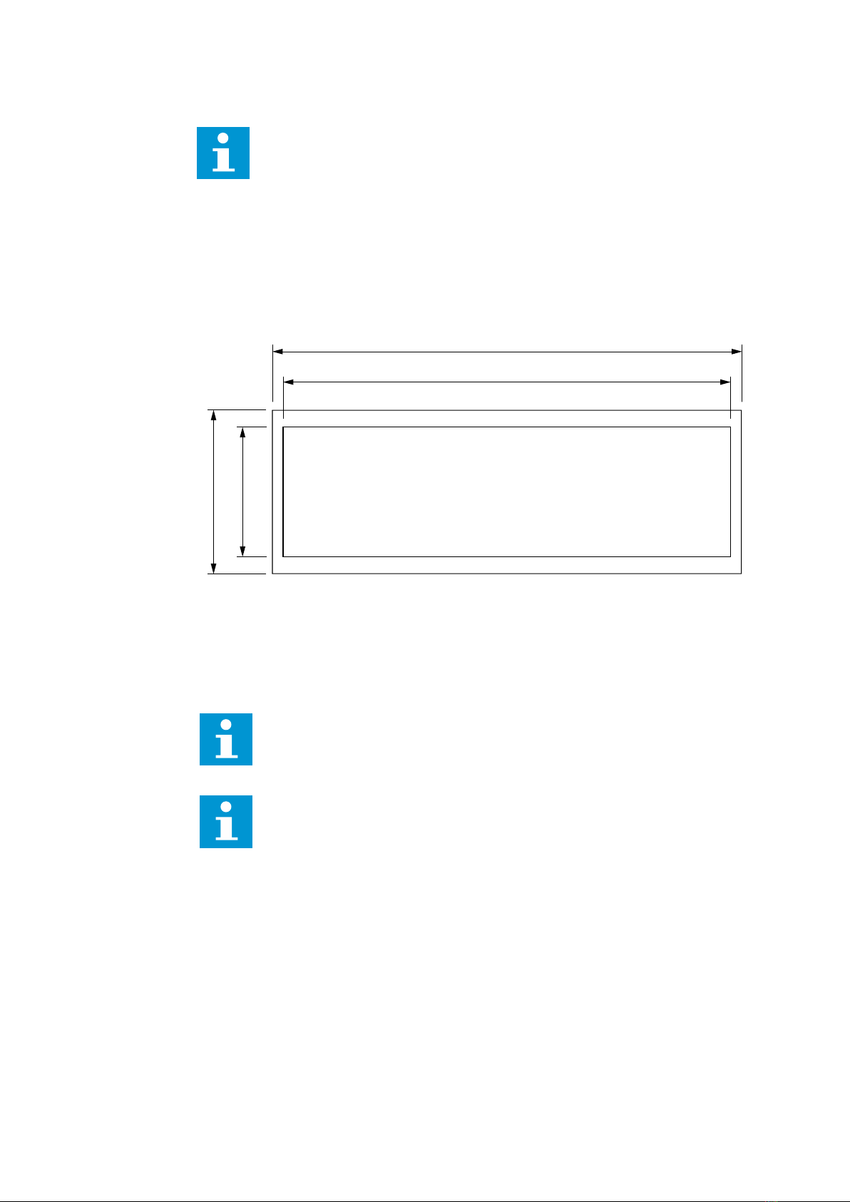
installation. The maximum size of the EVSE package is 920x1170x2430 mm (LxWxH). Note:
These details are for each cabinet.
•For locations where the EVSE is exposed to direct sunlight and high ambient temperatures for
most of the day, it is required to install protection from direct sunlight or place the EVSE under
shade.
•For locations where the EVSE is exposed to the possibility for collisions with vehicles, it is highly
recommended to install collision prevention equipment. This may be in the form of bollards or a
significantly raised curb/EVSE footing.
•For locations with significant snow accumulation or snow drifts, it's recommended to install
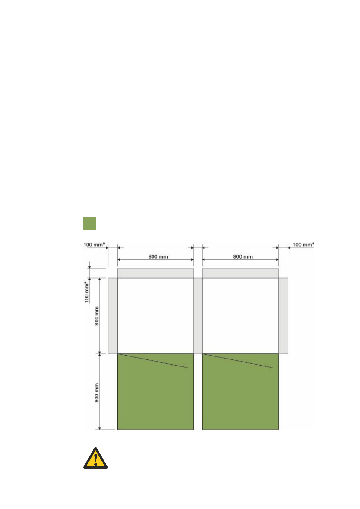
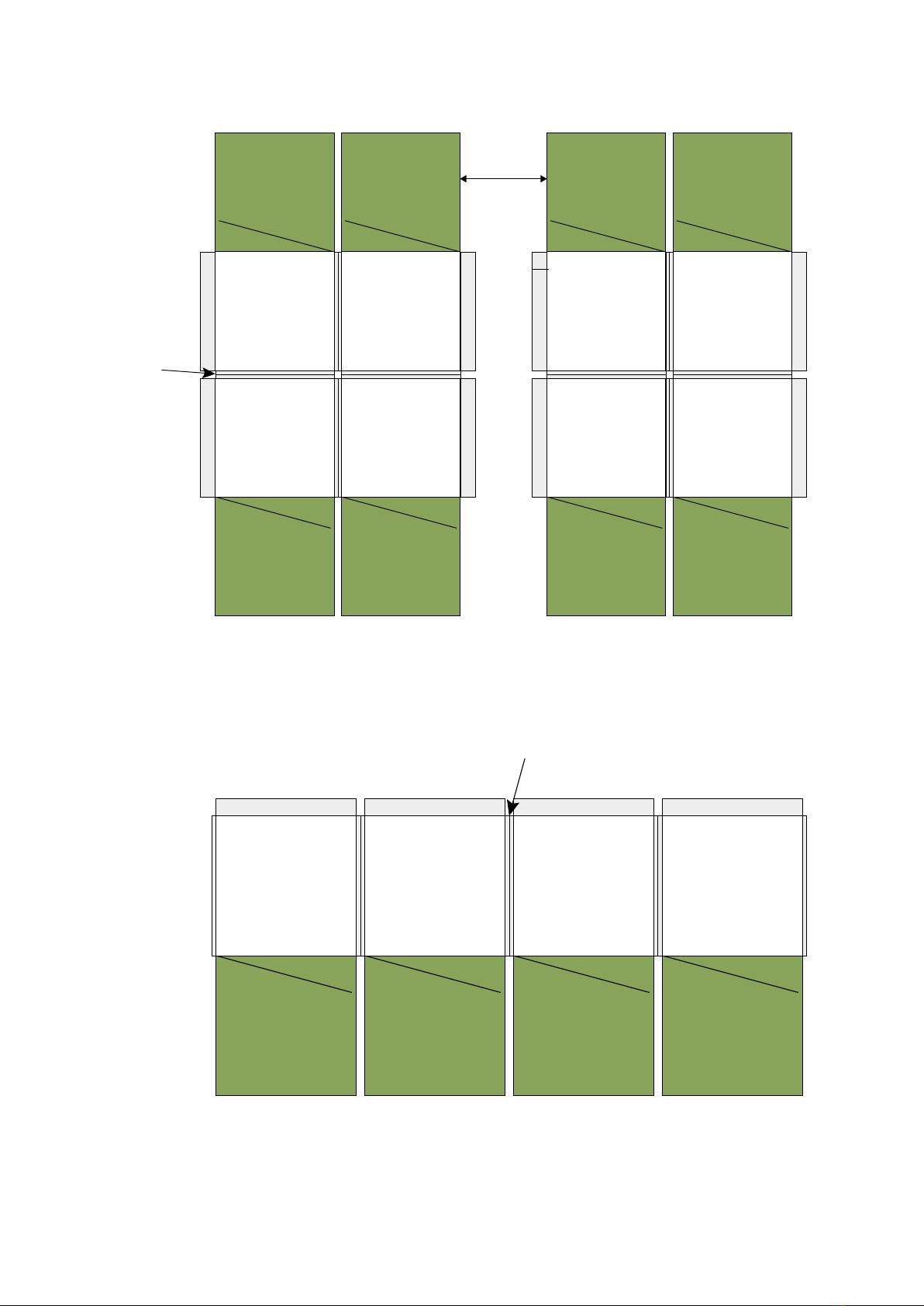
barriers or a shelter to protect snow from blocking air intake vents. Airflow needs should be
respected in all installations. The EVSE is air cooled by a set of internal fans which take in the
air from the ventilation grids in the bottom of the charger cabinet and release the warm air from
the ventilation grids in the top of the charger cabinet. The air intake has filters to prevent
contamination of the internal side of the charger cabinet. Keep the ventilation grids free from
debris and obstacles to allow for a free flow of air.
•The maintenance tasks for the EVSE are done from the top and the front of the charger
cabinet. Consider this when spacing units and planning service with vehicles present.
•The operation area is at the front of the charger cabinet. Normally, the charging process is
started, monitored, and stopped automatically by the EV. In case of abnormal operation, it is
possible to stop the charging process with the Charge abort button or the emergency stop
button.
•The escape routes are very location specific and shall comply with the national and local rules
and regulations. Keep in mind that a safe escape route is provided during the maintenance
tasks (with the door open).
•The base unit can supply from 1 to 3 external DC outlets. Even if these are not initially all
deployed, reservation of space is prudent to allow future expansion.
6

Floorplan 2.2
The EVSE is designed for a side-by-side installation, with the back of the cabinet against a wall or
freestanding. Due to air cooled ventilation the bottom of the EVSE has to be free from debris or
obstruction.
It is mandatory to respect a clearance of 100 mm at the rear and in between separate units. In the
front, the recommended clearance is 1500 mm to provide space for servicing the equipment. Note
that these clearances may be significantly impacted by site-specific situations such as a restriction
in accessibility that require further clearance consideration for egress. Please consult with local site
engineering as needed.
Measurements shown in the image below are recommended clearances. 10 mm is the minimum
clearance between the EVSE and other EVSE or objects at the back and sides. This clearance
requires a fork-lift installation.
* 100 mm of clearance between units at the back and sides is the recommended in order to allow
space provisions that make the installation possible with a crane or hoist.
Note: The two cabinets are linked with each other.
Maintenance area
Caution
When planning a site layout, additional space may be required to allow for a safe
route of egress. All local codes for safe egress must be followed.
7

Block configuration
Line configuration
2.2.1
2.2.2
31 inch (800 mm)
B
EVSE EVSE
EVSE EVSE
Air blow-out
Air blow-out
Air blow-out
Air blow-out
A
31 inch (800 mm)
EVSE EVSE
EVSE EVSE
Air blow-out
Air blow-out
Air blow-out
Air blow-out
A Minimum clearance of 15 mm per product creates 30 mm minimum spacing between.
B The distance between two blocks must be at least 610 mm.
A Minimum clearance of 15 mm per product creates 30 mm minimum spacing between.
Note: The cabinets are placed next to each other.
EVSE EVSE
Air blow-out Air blow-out
EVSE
Air blow-out
EVSE
Air blow-out
A
8

Cable gland plate
2.2.3
Note:
The details below are for each of the base product cabinet.
Note:
Installer is responsible to ensure that the enclosure rating of the cabinet is
maintained while complying with local codes and installation standard.
Note:
Custom gland plate composition can be provided:
1. Blank plate
Installer is responsible of fabrication and mainlining the enclosure rating of
the cabinet.
2. Custom fabricated plate
Installer explains Heliox which holes at which position are required.
Installer is responsible of fabrication and mainlining the enclosure rating of
the cabinet.
A cable gland plate is provided. This plate may come from the factory several ways: 1. it may be
solid, to allow for field punching, 2. It may be pre-drilled to allow easily sourced cord grips, or 3. it
may be pre-populated with standard cord grips.
By default, a blank plate is provided.
When openings for 3 cord grips are present but not used, make sure to close these openings with
IP54 approved methods to ensure the IP54 rating.
The outer dimensions mentioned on the plate are the dimensions of the cable gland plate. The
inner dimensions are the available space for drilling and placing glands.
586 mm
615 mm
170 mm
215 mm
9

3. Civil work
Note:
The details below are for each of the base product cabinet.
For most installations, some form of civil work will be needed.
It is the responsibility of all parties working on the project to ensure the civil, mechanical, and
electrical works are executed in compliance with the, local and national codes, standards, rules
and regulations.
It is the sole responsibility of the site owner, to make sure:
•the civil works are executed in compliance with the, local and (inter) national Directives,
Standards, Rules and Regulations;
•the AC cable is protected against the ground water;
•the DC cable is routed in its own duct and protected against ground water;
•the PE and CP (optional signal) cable, AC auxiliary cable are routed in their own duct and
protected against ground water;
•the cable ducts are buried at least 50 cm apart, or routed in EMC shielded cable trays.
Danger:
Failing to adhere to these points may result in a variety of consequences from
damaged equipment to personal harm or death.
Note:
Al cable ducts must be protected for ingress of water. An underground cable duct
does protect of ground water, however if open at surface level, then also rain or sea
water might flood into the duct, worsening the electric behavior and can cause
situation in which the charger goes over to a malfunction state.
10

Note:
Depending on the number of external DC outlets, several sets of output conduits
may reside in the up to 3 output areas.
Note:
The information below are for each of the base product cabinet.
Note:
The cable ducts need to be mounted just a bit above the ground (20 – 50 mm), to
prevent water entering the duct.
The foundation 3.1
800 mm
700 mm
800 mm
600 mm
100 mm 100 mm
50 mm 50 mm
A
A
A
A
Front
The EVSE is placed on the foundation.
The foundation shall be as flat as
possible with a maximum slant of 2 mm
across the bottom of the EVSE
equipment. Please see the specification
section of the technical handbook for
details on product weight. Please consult
local code for appropriate foundation
design to comprehend regional needs.
A: M12 anchor bolts are required to
mount EVSE equipment to the
foundation surface. Consult with site
engineering for requirements on bolt
depth, epoxy, and any special
requirements resulting from the
foundation medium.
Input conduits:
•AC inputs
Output conduits:
•DC output
•AC output wiring
•Signal interface wiring
11

Ventilation 3.2
Note:
The details below are for each of the base product cabinet.
Note:
When the iron grids are rotated, the IP degree of IP54 is affected for the water
ingress part, Take this into account. Dust ingress however is not affected.
The EVSE is air cooled by a set of internal fans which take in the air from the ventilation grids in the
bottom of the charger cabinet and release the warm air from the ventilation grids in the top of the
charger cabinet. The air intake has filters to prevent contamination of the internal side of the
charger cabinet.
Keep the ventilation grids free from debris and obstacles to
allow for a free flow of air.
The airflow of the exhaust of the charger can be directed
upwards or downwards. By default the iron grids are installed
to blow of downwards. This blow downwards configuration is
mandatory when the chargers are placed outdoor, in an
environment where water can fall on the charger or in any
other situation that it is demanded that the water ingress/IP
degree must be at least IP54.
For indoor installations where there will be no water falling on
the charger, the iron grid of the exhaust can be rotated such
that the blow off is upward. This is beneficial to take hot air
away when the chargers are installed indoor and where the
air-removal is at the top/ceiling of the room the chargers
are in.
Upward blow off
Downward blow off
12

4. Mechanical installation
The mechanical installation is executed either by a dedicated party of Heliox, or it is the scope of supply
of the site owner. For details, refer to contract as signed and agreed upon.
Note that the mechanical installation requires hoisting or lifting tasks.
It is the sole responsibility of the installer, to make sure:
•the mechanical installation work is executed in compliance with the, local and (inter) national
Directives, Standards, Rules and Regulations;
•the Hoisting and lifting work is executed by certified persons and valid equipment.
Danger:
Failing to adhere to these points may result in a variety of consequences from damaged
equipment to personal harm or death.
Caution:
Be careful when you handle the coated (painted) parts. Damaged coating can cause
corrosion. Corrosion can cause (serious) damage to the parts in the future.
Note:
The details of the mechanical installation mentioned below are for each of the base
product cabinet.
13

1. Put the pallet with the cabinet on a flat and stable surface with sufficient space to work.
2. Remove and discard the packaging material.
3. Dispose of the packaging material in accordance with the local regulations.
1. Remove the screws (1) on both ends and the
ventilation grid (2).
2. Put the parts in a safe place to prevent damage.
3. Remove the demister filter (1) from the cabinet (2).
4. Remove the dust filter. Shift the filter within its bracket
upwards. Pull/swing out at the bottom to the front.
Remove it.
5. Find and remove the screw bolts with the
washers (1) that attach the cabinet (2) to the pallet (3).
6. Also behind the back panel the charger is screwed
to the pallet. Remove and discard the screw bolts
with washers (there is no filter or demister present
at the back).
7. Make sure, the fork lift truck is valid for the work and the driver is certified.
8. Before lifting, for stability purposes, close and lock the door.
9. Carefully, drive the forks into the forklift pockets.
10. Carefully, remove the cabinet from the pallet and put it on a flat and stable surface.
11. Remove the pallet from the work area.
Preparation
Use a forklift to transport the charger
4.1
4.2
Note:
The fork lift pockets are blind, there is an endplate. Note that the forklift pockets allow
for a fork width of 130mm.
14

1. Remove the bolts (1) on top of the roof (4x).
2. Mount the lifting eyes (2) instead (4x).
3. Connect the lift to the lifting eyes.
4. Before lifting, for stability purposes, close and lock the door.
5. Lift the cabinet and move it to a flat and stable surface.
Note that this operation may be done via hoisting, as described, or by fork lifting procedure.
Remove the charger cabinet from the pallet
4.3
1
2
15

Danger:
Risk of electrocution. Make sure, it is safe to work on the electrical installation. Energized
electrical systems are hazardous and can cause electrical shock. Electrical shock can
cause (serious) injury to persons.
5. Electrical installation
The AC electrical installation is executed either by a dedicated party of Heliox, or it is the scope of supply
of the site owner. For details, refer to contract as signed and agreed upon.
It is the sole responsibility of the site owner:
•to install and connect the AC power supply between the AC power supply grid and the EVSE;
•to install, when stipulated by local rules, to install and connect an earth electrode next to the charger
cabinet;
•to make sure, the AC power supply is compliant with the (inter) national Directives, Standards, Rules
and Regulations.
Failing to adhere to the local and (inter)national Directives, Standards, Rules and Regulations, guidelines
and technical details herein can result in unforeseen problems and delays of any kind.
The AC power supply is connected to the phase widgets extensions of the main circuit breaker in
the EVSE. The cables must be terminated and connected in accordance with the instructions as
given by the manufacturer and (inter) national Directives, Standards, Rules and Regulations.
After the cable lugs are installed, torque tightened, apply a torque mark for future reference. The
torque values are listed in the section: Technical specifications.
It is mandatory to make sure, the feed through of the incoming cables are closed to prevent
rodents to enter the cabinet.
Electrical power connection
5.1
Note:
The details of the electrical installation mentioned below are for each of the base
product cabinet.
16

Incoming AC power supply:
TN-C: 3P+PE
TN-S: 3P+N+PE
Short current rating: 35kA
This unit must be connected to a grounded, metal, permanent wiring system; or an equipment-
grounding conductor is to be run with circuit conductors and connected to equipment-grounding
terminal or lead on battery charger. Connections to battery charger shall comply with all local
codes and ordinances.
1. Set the switches in the off position.
2. Lock-out/Tag-out the upstream supply to the EVSE and the related systems to prevent
that the EVSE can get energized unintentionally.
3. Make sure, the electrical parts and connections are clean, dry and free of corrosion.
As applicable, the AC power supply cable can be executed as a multicore cable or as separate
cables. The AC power supply has the phases (L1, L2 and L3), neutral (N) and the protective earth
(PE).
It is assumed that the AC power supply cable has copper cores and the cable lugs have a tinned
surface.
1. Do a visual inspection for damage and contamination.
- The cable is clean and shows no signs of damage.
2. Feed the AC power supply cable(s) into the EVSE.
3. Allow for sufficient over length for future repair of the connections.
4. Install the cable lug and the shrink sleeve to the cable in accordance with
the manufacturer's instructions.
AC configuration
Grounding instructions
5.1.1
5.1.2
5.1.3
Electrical power connection
5.2
Note:
Narrow cable lugs are needed for AC connection, standard cable lugs will not fit.
17

1. Feed the AC power supply cable(s) into the EVSE.
2. Allow for sufficient over length for future repair of the connections
3. Make sure, sufficient length is available for 3x a repair session.
4. Install the cable lug and the shrink sleeve to the cable in accordance with
the manufacturer's instructions.
1. Flat washer
2. Conical spring washer (Belleville)
3. Bolt, M10
4. Cable lug
5. Shrink sleeve
6. Cable
7. Busbar
8. Flat washer
9. Nut
Connect the AC power supply cables
Connect the Output Connections
5.3
5.4
Caution:
Be careful when you install the conical spring washer. The hollow side must face the
busbar. Incorrect installed conical spring washers are not short-circuit proof.
Incorrect installation will cause (serious) damage to the equipment.
When an external EV coupler is used, the responsible parties must reference the detailed
information provided in the documentation that comes with the EV-coupler.
•The items in sections preceding this still apply in order to install the base unit.
•An additional set of outputs is needed to be installed to connect the base unit to the external
coupler or couplers.
•The DC cable shall be routed in its own duct.
•The PE and CP (optional signal) cable shall be routed in their own duct with the control wires
and Ethernet.
•The 400VAC supply shall be routed in its own duct
•The DC and CP ducts shall be at least 500 mm away from each-other, or routed in EMC
shielding raceways such as rigid conduit.
The DC+ and DC- cables of the external DC outlet must be connected onto the interface panel
inside the base module to the DC+ and DC- connections. The other connections must be made
onto the terminal strip in output groups from left to right (X501, X502, or X503) as called for in a
site-specific system layout.
Earth cable must be connected to rail A-PE1.1.
Note:
The EVSE unit described in this manual may support several different output
configurations. Please refer to the site system layout documentation along with the
EV-coupler documentation for detail on all connections needed at a site.
18

Output terminal connections
5.4.1
Cable
Function
Wire
color/number
Base station
connection
AC IN
L1
BK1
X501:1
L2
BK2
X501:2
L3
BK3
X501:3
N
BU
X501:4
PE
GN/YE
X501:PE
CAN from base product
CAN_H
WH
X501:5
CAN_L
BN
X501:6
Shield
500SH2
Low voltage interface
Not used
X501:7
Not used
X501:8
Emergency stop from
base product
Emergency Stop 1
BK1
X501:9
Emergency Stop 2
BK2
X501:10
Interlock In (Door switch
from base product)
Door 1
BK3
X501:11
Door 2
BK4
X501:12
Ethernet from base
product
Communication
X501:13
Note:
If the X501 group is not available, use the next terminal strip group available from left
to right (X502 or X503).
19

Interconnection between cabinets
Output terminal wiring
5.4.2
5.4.3
The interconnections between cabinets must be made at the moment of installation of the
cabinets.
The wiring mentioned here is recommended, but may not be compliant with local code. Please
consult with qualified site engineering personnel to ensure and select wiring that meets all local
codes and regulations.
*Note: Cab A & cab B are the master cabinet and slave cabinet respectively for the Flex 360KW
charger.
Cable
Function
Wire
color/
number
The base station connections*
interlink between two
cabinets
CAN from base
station
CAN_H
WH
X503:5 (cab A) – X503:5 (cab B)
CAN_L
BN
X503:6 (cab A) – X503:6 (cab B)
Shield
500SH3 (cab A) – X500SH3 (cab B)
Incoming PE/GND
interconnection
PE/GN
GR/YE
PE/GND1 busbar (cab A) - PE/
GND1 busbar (cab B)
Emergency stop
from base product
Emergency Stop 1
BK1
X503:9 (cab A) – X503:9 (cab B)
Emergency Stop 2
BK2
X503:10 (cab A) – X503:10 (cab B)
Fixed installation with remote cabinets
Mnemonic
Function
Cable example
Connection
E-stop
Emergency stop
Lapp, Ölflex, 190 CY,
4xAWG18
Ferrules/snap-in
Interlock
Enable system
CAN
CAN communication
Lapp, Unitronic BUS
CAN, 1x2x22AWG
Ferrules/snap-in
ETH
Ethernet
communication
Lapp, Etherline PN Cat.
7, 4x2x23/1AWG
Ferrules/snap-in
AC Supply
3P+PE/GND+N OR
3P+PE/GND
Lapp, Ölflex, 190 CY,
4x12AWG
Ferrules/snap-in
Note:
Any other brand for the cable connections may be used as long as specifications are
the same or better.
20
Table of contents
Other Paccar Batteries Charger manuals
Popular Batteries Charger manuals by other brands

Schumacher
Schumacher 520A-PE owner's manual

SWELLPRO
SWELLPRO Dual Smart Charger user manual

Inkel
Inkel IBC-8224 Operation manual

ASSOCIATED EQUIPMENT CORPORATION
ASSOCIATED EQUIPMENT CORPORATION 6065 Operator's manual

BASETech
BASETech BTL-100 operating instructions

Draper
Draper BCD18A Original instructions