PairGain HiGain -2 HLU-611 User manual

PARGAIN TECHNOLOGIES SECTION 150-611-103
Technical Practice Revision 01
Engineering - PLANT Series July 14, 1995
Page 1
PAIRGAIN TECHNOLOGIES HIGAIN-2™LINE UNIT
MODEL HLU-611 Issue 1
List 3 PairGain #150-1217-03 CLEI Code: T1L1JJK3AA
CONTENTS PAGE
A. PRODUCT OVERVIEW 2
1. DESCRIPTION AND FEATURES 2
2. APPLICATIONS 2
3. SPECIFICATIONS 3
4. CERTIFICATION 4
5. WARRANTY 4
6. TECHNICAL ASSISTANCE 4
B. FUNCTIONAL DESCRIPTION 4
7. FUNCTIONAL OPERATION 4
8. OPTIONS 7 8
9. LOOPBACKS 8 9
C. INSTALLATION AND TEST 12
10. INSTALLATION 12
11. TESTING 13
CAUTION
This product incorporates static sensitive
components. Proper electrostatic discharge
procedures must be followed.
Figure 1. HLU-611 Front Panel. The PairGain HLU-611
is the Central Office side of a single pair repeaterless T1
transmission system.

Section 150-611-103
Revision 01
Page 2
A. PRODUCT OVERVIEW
1. DESCRIPTION AND FEATURES
1.01 PairGain’s HiGain-2 Line Unit Model HLU-
611 Issue 1, List 3 Figure 1, is the Central
Office side of a single pair repeaterless T1
transmission system. When used in conjunction
with an HRU-612 HiGain-2 Remote Unit, the system
provides 1.544 Mb/s transmission on 1
unconditioned copper pair over the cable ranges
shown in Table 1. The HiGain-2 system uses
VHDSL (Very High-bit-rate Digital Subscriber Line)
transmission technology. HiGain-2 complies with
TR-TSY-000063 (Network Equipment Building
System (NEBS) Generic Equipment requirements)
and TR-TSY-000499 (Transport System Generic
Requirements - TSGR) common requirements.
1.02 Revision History of this practice.
Revision 01 — July 14, 1995
a) Initial release.
1.03 HLU-611, List 3 features:
• Selectable DSX-1 Pre-equalizer
• -170 Vdc Line Power for HRU-612
• Front Panel VHDSL S/N Margin Display
• Selectable Loopback activation codes
• RS-232 maintenance port
• Non-volatile front-panel operator setup
• Front Panel DS1 splitting & brdg access
• Lightning and power cross protection on
VHDSL interfaces
• 1568 kb/s full-duplex 2B1Q VHDSL
Transmission on pair
• Front panel status indicating LED.
• On / Off front-panel display power cycling.
• DS1 LOS detector (125 consecutive
zeros).
• Margin threshold alarm.
• Smart-jack AIS option.
• Easy return to factory default user
settings.
• Circuit ID option
2. APPLICATIONS
2.01 HiGain-2 provides a cost-effective, easy to
deploy method for delivering T1 high
Capacity Digital Service (HCDS) over 1 metallic pair.
The fiber-like quality service is deployed over 1
unconditioned, non-loaded copper pair.
Conventional in-line T1 repeaters are not required.
Cable pair conditioning, pair separation and bridged
tap removal, are not required.
2.02 The general guidelines on which the range
deployment rules in Table 1 are based
require that each HiGain-2 loop have less than 35
dB of loss at the 2B1Q line rate of 392 kHz, with 135
ohm driving and terminating impedances, adherence
to this rule will result in an operating margin of at
least 6 dB. The HiGain-2 system operates with any
number of other T1, POTS, Digital Data Service
(DDS) or other HiGain-2 Systems sharing the same
cable binder group. HiGain-2 systems can be used
with customers requiring DS1 service on a
temporary or permanent basis. HiGain-2 also
provides a means of quickly deploying service in
advance of fiber-optic transmission systems. With
HiGain-2, service can be provided within hours.
Fiber optic systems can be installed at a leisurely
pace and cut-over from HiGain-2 when convenient
to do so. The HiGain-2 system can then be easily
removed and utilized elsewhere.
TABLE 1. HIGAIN-2 VHDSL LOOP LIMITS
Cable Gauge Loss @ 392
kHz dB/kft Ohms per kft Maximum Loop For
35 dB Loss Ohms @ Maximum
Loop Length
26/0.4 mm 4.97 83.3 7.0 kft / 2.13 km 583
24/051mm 3.87 51.9 9 kft / 2.74 km 467
22/0.61mm 3.01 32.4 12 kft / 3.66 km 389
19/0.91mm 2.17 16.1 16 kft / 4.87 km 258

Section 150-611-103
Revision 01
Page 3
3. SPECIFICATIONS
VHDSL Line Code
1568 kb/s 2B1Q.
VHDSL Output
+13.5 dBm +/- 0.5 dB @ 135 ohms .
VHDSL Line Impedance
135 ohms.
Maximum Provisioning Loss
35 dB @ 392 kHz, 135 ohms.
Line Clock Rate
Internal Stratum 4 clock.
VHDSL Startup Time
30 seconds typ., 60 seconds max.
One-way DS1 Delay
<220 microseconds.
DSX-1 Line Impedance
100 ohms.
DSX-1 Pulse Output
12V pk-pk for EXTERNAL equalizer or pre-
equalized for 0-655 feet of ABAM.
DSX-1 Input Level
+1.5 to -7.5 dBDSX.
DS1 Line Rate
1.544 Mb/s +/- 200 bits/sec.
DS1 Line Format
AMI, B8ZS or ZBTSI.
DS1 Frame Format
ESF, SF or unframed.
Power Consumption
14 watts typ.; 18 watts max.
Heat Dissipation
6 watts typ.; 8 watts max.
Fusing
Internal;connected to “FUSEALARM” output on
pin 32.
Span Voltage
-170 Vdc max.
Margin Indicator
Displays span SNR margin for both spans relative
to 10-7 BER operation.
Electrical Protection
Secondary surge protection on DS1 & VHDSL
ports. Power cross protection on VHDSL port.
Operating Temperature & Humidity
0 to 50º Celsius, 5 to 95% (non-condensing)
Mounting
AT&T 220 type or equivalent.
Dimensions
5.9”Hx1.4”Wx10”D.
MICROPROCESSOR
-FUSE
ALAR M
15
POWER
SUPPLY
B
A
B
35
34TIP1
RING 1
VHDSL
40
32
STATUS
A
RS-232
42
43
TIP
RING
D
S
X
1
RCV
49
50
TIP1
RING 1
SPAN
SPAN
XMT
D
S
X
1
BRG
BRG
MUX
DEMUX
PRE-
EQUALIZER
SELECT
MODE SEL
170V
POWER
SUPPLY
(ISOLATED)
39
19
44
16
20
21
ALRM
GND
BAT
-48V
Figure 2. HLU-611 Block Diagram.

Section 150-611-103
Revision 01
Page 4
4. CERTIFICATION
4.01 FCC compliance: The HLU-611 has been
tested and found to comply with the limits
for a Class A digital devices pursuant to Part 15 of
the FCC rules. These limits are designed to provide
reasonable protection against harmful interference
when the equipment is operated in a commercial
environment. This equipment generates, uses and
can radiate radio frequency energy and, if not
installed and used in accordance with the instruction
manual, may cause harmful interference to radio
communications. Operation of this equipment in a
residential area is likely to cause harmful
interference in which case the user will be required
to correct the interference at his own expense.
5. WARRANTY
5.01 PairGain Technologies warrants this product
to be free of defects and to be fully
functional for a period of 36 months from the date of
original shipment, given proper installation. PairGain
will repair or replace any unit without cost during this
period if the unit is found to be defective for any
reason other than abuse or improper use or
installation.
5.02 This module should not be field repaired. If
it fails, replace it with another unit and return
the faulty unit to PairGain for repair. Any
modifications of the unit by anyone other than an
authorized PairGain representative voids the
warranty.
5.03 If a unit needs repair, call PairGain for a
Return Material Authorization (RMA)
number and return the defective unit, freight prepaid,
along with a brief description of the problem, to:
PairGain Technologies, Inc.
14402 Franklin Avenue
Tustin, CA 92680
ATTN: Repair and Return Dept.
(714) 832-9922
(800) 638-0031
6. TECHNICAL ASSISTANCE
6.01 PairGain Technical Assistance is available
24-hours-a-day, 7-days-a-week by
contacting PairGain’s Customer Service Engineering
group at one of the following numbers:
Telephone: (800) 638-0031
(714) 832-9922
Fax: (714) 832-9924
During normal business hours (8:00 AM to 5:00 PM,
Pacific Time, Monday - Friday, excluding holidays),
technical assistance calls are answered directly by a
Customer Service Engineer. At other times, a
request for technical assistance is handled by an on-
duty Customer Service Engineer through a callback
process. This process results in a callback within 30
minutes of initiating the request.
In addition, PairGain maintains a computer bulletin
board system for obtaining current information on
PairGain products, product troubleshooting tips and
aids, accessing helpful utilities, and for posting
requests or questions. This system is available 24-
hours-a-day by calling (714) 730-3299.
Transmission speeds up to 28.8 kbps are supported
with a character format of 8-N-1.
B. FUNCTIONAL DESCRIPTION
7. FUNCTIONAL OPERATION
7.01 HiGain-2 utilizes PairGain’s 2B1Q VHDSL
transceiver systems to establish one full-
duplex 1568 kb/s data channels between the HLU-
611 and a remotely mounted HRU-612 HiGain-2
Remote Unit.
7.02 A block diagram of the HLU-611 is shown in
Figure 2. The HiGain-2 HLU-611 receives a
1.544 Mb/s DS1 data stream from the DSX-1 digital
cross connect interface. The HLU contains a DS1
frame synchronizer controlled by an 8-bit micro
controller that determines the type of framing on the
DS1 stream and synchronizes to it. The HLU-611
recognizes SF(including D4) or ESF framing. When
the data is unframed, the HLU-611 arbitrarily defines
a frame bit.

Section 150-611-103
Revision 01
Page 5
7.03 The HLU-611 contains a demultiplexer that
generates a 1568 kb/s data stream. The
data stream contains VHDSL frames that are
nominally 9408 bits (6 milliseconds) in length. The
VHDSL frames contains a 14 bit Frame Sync Word
(FSW), 6 bit Cyclic Redundancy Check (CRC), 21
bit operations channel and DS1 payload.
7.04 The formatted VHDSL channel is passed to
the VHDSL transceiver which converts it to
a 2B1Q format on the VHDSL line. The 2B1Q line
code is designed to operate in a full-duplex mode on
one unconditioned pair. The transceiver’s echo
canceler and adaptive equalizer receive the signal
from the remote end in the presence of impairments
and noise on the copper pair.
7.05 The received VHDSL channel is processed
by the transceiver and then passed on to the
HLU-611 multiplexer module. The multiplexer
provides frame synchronization for the VHDSL
channel. The multiplexer and VHDSL transceiver
work under control of the HLU-611 micro controller
and compensate for data inversions caused by tip-
ring reversals. By synchronizing to the FSW of the
VHDSL channel, the multiplexer can reconstruct the
original 1.544 Mb/s DS1 stream from the VHDSL
channel. The CRC fields on the VHDSL streams
allow the HLU-611 to determine if errors are present
on the channel due to excessive impairments on the
VHDSL pairs or due to excessive impulse or
crosstalk noise.
7.06 The multiplexer removes data link
messages from the VHDSL channel and
passes them to the micro controller. This
mechanism allows operations messages and status
to be exchanged between the HLU-611 and the
HRU-612 remote unit.
7.07 The reconstructed VHDSL data channel is
buffered in a first-in-first-out buffer (FIFO)
within the multiplexer. A frequency synthesizer in
conjunction with the FIFO regulates the output bit
rate and reconstructs the DS1 clock at the exact
rate received from the remote end. The HiGain-2
system operates at DS1 rates of 1.544 Mbs with up
to ±200 bits/second of offset.
7.08 A DSX-1 interface driver converts the DS1
channel to an AMI or B8ZS format. The
DSX-1 equalizer is programmable to 5 different
lengths as determined by the distance between the
HLU and the DSX-1 interface. This provides CB-
119 compliant pulses at the DSX-1 interface over a
range of 0-655 feet of ABAM cable.
7.09 The HLU-611 contains 2 separate power
converters. The main power supply
converts -48V local battery to logic power for the
HLU-611 circuits. The line power supply converts
the -48V battery to a -170 Vdc feed that provides
loop power feed on the cable pair to the HRU Unit.
The line power supply can be turned on or off by the
micro controller and is automatically shut down in
the presence of line short circuits or micro controller
failure.
7.10 The three most important power demands of
an HLU-611 on the shelf power supply are
its maximum power consumption, its maximum
power dissipation and its maximum current drain.
These three parameters for the HLU-611, on a per
slot and per shelf basis, are as follows:
Maximum Power Dissipation:
• Per Slot = 7.0 Watts
• Per Shelf =91 Watts
Maximum Power consumption:
• Per Slot = 16 Watts
• Per Shelf =208 watts
Maximum Current Drain:
• Per Slot = 0.376 Amps
• Per Shelf =4.9 Amps.
Note that the worse case conditions under which
these parameters were measured include a 7,500 ft.
# 26 AWG loop, 60 mA. of CPE current, a fully
loaded 13 slot shelf, and a 42.5 V shelf battery
voltage.
7.11 The Maximum Power Dissipation measures
the power that is converted into heat build
up within the unit. It contributes to the total heat
generated in the space around the unit. It is used to
determine the maximum number of fully loaded
shelves per bay that does not exceed the maximum
allowable power dissipation density in Watts/sq. ft.

Section 150-611-103
Revision 01
Page 6
7.12 In Central Office locations, the maximum
power dissipation for open faced, natural
convection cooled mountings is limited to 120 W /
sq. ft. per Section 4.2.3 of the NEBS standard TR-
NWT-000063. The footprint of a 13 slot 23 “ HLU-
611 shelf is 7.024 sq. ft. Thus the maximum bay
dissipation is limited to 840 Watts. At 91 watts per
shelf, this limits the number of fully loaded HLU-611
shelves to 9 per bay. Note that this is a worse case
situation in that it assumes the entire Central Office
is subjected to the maximum power density.
Conditions other than these worse case ones would
permit increasing the number of shelves per bay
without jeopardizing the C.O.’s thermal integrity.
7.13 The thermal loading limitations imposed
when using the HLU-611 in CEVs or other
enclosures are determined by applying the HLU-
611’s power parameters to the manufacturer’s
requirements for each specific housing.
7.14 The Maximum Power Consumption is the
total power that the HLU-611 consumes or
draws from its -48 V shelf power source. This
parameter is needed when the 611 is located remote
to its serving C.O. It determines the battery capacity
required to maintain an 8 hour stand-by battery
reserve for emergency situations. It thus limits the
maximum number of plugs per remote enclosure.
Use the above data to perform this analysis on a
case by case basis.
HLU-611
DCE
FEMALE MALE
2
5
3
2
5
3
RD(RECEIVEDATA)
TD(TRANSMITDATA)
GND
DB9
DB9
DTE
DTE
TERMINAL
TERMINAL
3
2
7
DB25
Figure 3. DB-9 Pin-outs.
7.15 The Maximum Current Drain is the
maximum current drawn from the shelf power
supply when it is at its minimum voltage (42.5 V).
This determines the shelf fusing requirements.
HLU-611 shelves are normally fused at 10 amps. A
fully loaded shelf of 13 HLU-611s draws 4.9 amps in
the worst case. This is well within the 10 amp fuse
limit.
7.16 A 9-pin (RS-232) DB-9 connector (see
Figure 3), is provided on the front panel.
This connector provides access to HiGain-2’s
maintenance, provisioning and performance
monitoring interface. A very basic interface is
available via a ‘dumb terminal’. Figures 7 through
13 show the menu selections that are available from
the terminal. The port is configured as DCE with 8
data bits, 1 stop bit and no parity. Striking the
SPACE bar several times invokes autobaud from
1200 to 9600 b/s.
7.17 The normally open alarm contacts available
across pins 20 & 21 comprise the HLU-
611’s minor alarm output. These alarm contacts
close for any of the following alarm conditions. Note
that the front panel message which accompanies
each alarm condition is shown in bold letters before
each alarm condition. Since more than one alarm
condition can exist at any given time but only one
message can be displayed, the alarms are listed in
their order of priorities. Only the highest priority
alarm is displayed if more than one alarm condition
exists.
1) ALRM LOSW: The VHDSL loop loses sync.
2) ALRM LLOS: Loss of the HLU T1 input signal.
3) ALRM RLOS: Loss of HRU T1 input signal
4) ALRM HES: VHDSL Loop has exceeded the 24
hour user-selected Errored-Seconds (CRC)
threshold
5) ALRM DS1: The total number of bipolar
violations (BPV) at the HLU and HRU T1 input
have exceeded the 24 hour user-selected
threshold.
6) ALM MAL: The margin on the VHDSL Loop has
dropped below the minimum threshold value set
by the dumb terminal MARGIN ALARM THRES;
as described in Section 8.
The HLU 611’s STATUS LED flashes RED for the
duration of a minor alarm condition. Alarms 4 & 5
can be inhibited by selecting NONE for the ESAL

Section 150-611-103
Revision 01
Page 7
system option. See Section 8 for System Settings
information. The MAL1 alarm can be disabled by
setting the margin alarm threshold to 0. All six
alarms can be inhibited by selecting DIS (disable) for
the ALM system option. The MNALRM can be
retired by executing the ACO option. This is
accomplished by depressing the SEL button on the
front panel. This turns the alarm off and replaces
the ALRM message by the ACO message. The
second part of the ALRM message, which defines
the cause of the alarm, remains. Both messages
remain until the alarm condition clears or another
alarm occurs. Disabling the ALM also retires an
ACO condition.
7.18 Pin 32, FUSEALARM, is driven to -48 V and
the front panel STATUS LED turns red
whenever the on board fuse opens.
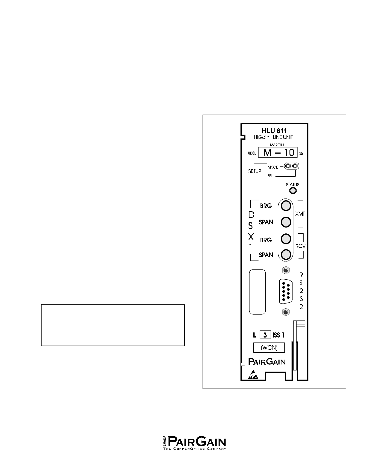
7.19 The HLU-611’s front panel tri-color
STATUS LED has the following states:
• GREEN - Normal Operation
• FLASHING GREEN - VHDSL Acquisition
• FLASHING RED - Minor Alarm (For
conditions see Paragraph 7.17)
• RED - FUSEALRM
• YELLOW - Self Test in process or an HLU
loopback in effect (CREM or NLOC).
• FLASHING YELLOW - The HLU is in an
ARMED state.
7.20 Depressing both the MODE and SEL
pushbuttons on the front panel for at least 3
seconds initiates a MANUAL loopback session. This
session allows the user to SEL one of four HiGain
loopbacks. The message, MAN LPBK, appears on
the front panel display followed by the message
NRE?. If the SEL button is now depressed, an
NREM loopback is executed and the message
changes from NRE? to NREM. If the MODE button
is depressed instead of the SEL button, NRE? is
replaced by NLO?. This now allows an NLOC
loopback to be executed with the SEL button.
Depressing the MODE button two more times yields
the CLO? (CLOC) and CRE? (CREM) customer
loopback options. This interactive button procedure
permits any of the four HiGain loopback to be
executed. Once a loopback is executed, it can be
terminated and the next loopback option presented
by depressing the MODE button. If neither button is
depressed for a period of 30 seconds, this manual
loopback session terminates and the normal margin
displays reappear. If this time-out occurs with an
active loopback in effect, the appropriate loopback
message appears in addition to the loop margin
messages. Once the manual loopback session
terminates, the loopback remains in effect until it
times-out in accordance with the user LBTO setting.
It can also be terminated by re-entering the manual
loopback mode and selecting another loopback.
Only 1 loopback can exist at any given time.
Depressing both buttons, again for 3 seconds,
terminates any active loopback, ends the MANUAL
loopback session and returns the display to normal.
Note that the loopbacks can be also initiated from
the RS-232 maintenance port by choosing the
LOOPBACK MODE, option “D” from the MAIN
MENU. This displays the Loopback Menu, shown in
Figure 14, from which any of the four loopbacks can
be initiated.
8. OPTIONS
8.01 The HLU-611 contains a non-volatile RAM
which stores the system option settings. No
dip-switches or jumpers are required to set the HLU-
611 configuration. The options are set via
pushbuttons on the front panel, through the RS-232
interface, or from the NMA interface and are
retained if shelf power is lost or if the HLU-611 is
unplugged. Table 2 lists the HLU-611 option
settings. Note that only those options enclosed by
quotes can be set by the front panel buttons. All 14
options can be set via the front panel RS-232
maintenance part. Figure 8 illustrates the same
options on the HLU-611 set-up menu.
8.02 The SETUP (MODE and SEL) momentary
pushbuttons are used to set the options
from the front panel. To initiate an OPTION
SETTING mode, depress the MODE button for 1
second and release. The message displayed on the
front panel alternates between the system
parameter and its current setting. Depressing the
SEL button steps the display through all possible
settings (one at a time) of the MODE (parameter)
being displayed. After the desired setting has been
chosen, depress MODE. This does two things.
First it updates the current displayed mode to the
setting chosen. It then selects the next configurable
parameter. After the last parameter has been
selected, the displays shows CONF/NO. If the
MODE button is now depressed, none of the
changed parameters are installed. If the SEL button

Section 150-611-103
Revision 01
Page 8
is depressed, a YES message is displayed and the
chosen changes are installed. In either case the
display returns to its normal mode. The display also
returns to its normal mode, without installing any
new changes, if neither button is depressed for 30
seconds.
8.03 All 14 user options can be set to their
default values by depressing the SEL button
for 6 seconds. When released, the message: “DFLT
NO” appears. To install the default values depress
the SEL button again. The “YES” will follow
indicating that the default values are now in effect.
To terminate this DFLT mode without reverting the
options to their default values, depress the MODE
button or do nothing for 30 seconds. The latter
returns the display to its normal state.
8.04 Depressing the MODE button for 3 or more
seconds causes the display to scroll through
the HLU’s software version number, its List #, the
type of frame pattern being received from the DSX-
1, the line code setting of the HLU and all 11 option
settings. See Table 9 for these additional
messages.
8.05 The following three user options must be set
with a dumb or smart terminal: CIRCUIT ID,
DS0 BLOCKING and MARGIN ALARM
THRESHOLD.
8.06 The CIRCUIT ID option is set by choosing
the “I” option from the dumb terminal’s main
menu shown in Figure 6. The message “enter
circuit ID #: 24 characters max” follows the “I”
selection hit the return key after entering the chosen
set of alpha-numeric ID characters. Then chose “C”
to confirm. Note if more than 24 characters are
entered, en error message appears. Simply delete
the excess characters and then hit the return key
once again. The ID appears in all HLU screens as
shown in Figures 6 through 13. The ID does not
appear on the HRU screens when the maintenance
port is accessed at the remote unit. Note that the
Circuit ID is not set to its default (all blanks) setting
when the DFLT setting option is utilized.
8.07 To set the DS0 BLOCKING option first
select the SYSTEMS SETTINGS (“D” choice)
from the main menu. The menu shown in Figure 8
appears. Now enter the letter “B” shown in
parenthesis of the DS0 blocking selection. The DS0
channels are blocked or unblocked by entering each
channel’s number. Multiple channels can be
selected by inserting a space between each entry.
After all the new settings have been made, enter “E”
for exit and then “C” for confirm. The new choices
are now installed. If DS0 blocking is invoked in a
HiGain-2 system that has an earlier HRU that does
not support the blocking option, blocking will only
occur at the DS1 output of the HLU. The HRU’s
DS1 output will not be blocked. Also, all blocked
channels are opened for all HiGain-2 loopback tests.
This allows the standard full bandwidth T1 loopback
tests to be performed.
8.08 To set the MARGIN ALARM THRESHOLD
select “G” from the system settings menu.
Enter the desired minimum acceptable alarm
threshold from the 0 to 15 dB range. This causes a
minor alarm to occur (see Paragraph 7.17) if the
margin on the VHDSL loop drops below the selected
threshold value. Since the margin can never drop
below 0, choosing ”0” for the margin threshold turns
the margin alarm off.
8.09 The other dumb terminal system settings
are set in a similar manner. Simply enter the
letter in parenthesis of the parameter to be changed.
Each entry of this letter scrolls the parameter to its
next value, hit the enter key after each selection is
madeAfter all selections have been made, enter “E”
and then “C” to the resulting Confirm message. This
activates the new choices and returns control to the
main menu.
8.10 The SELF-TEST mode that occurs when the
VHDSL loop is not in sync includes the
input DS1 transceiver chip in the self test procedure.
This process can cause the AIS pattern, that is
normally transmitted from the HLU during these out
of sync intervals, to exhibit occasional BPVs.
9. LOOPBACKS
9.01 HiGain-2 has a family of loopback options.
The most important of these is the Smart-
Jack loopback which enables the HRU-612 to
respond to the standard 2/3 in 5 Smart-Jack in-band
loopback codes. This option can be enabled or
disabled from either the front panel settings or the
dumb terminal system settings menu.
9.02 In addition to the Smart-Jack loopback,
HiGain-2 can be configured for one of five
special in-band loopback command sequences.
These are selected from the SPLB user option
shown in Table 2 and Figure 8. The loopback
locations are shown in Figure 5.

Section 150-611-103
Revision 01
Page 9
9.03 GNLB is the HiGain-2 Generic loopback
code. The GNLB allows 4 in 7 or 6 in 7 in-
band codes to loop-up the HLU (NLOC or CREM
respectively) and 3 in 7 or 4 in 7 in-band codes to
loop-up the HRU (NREM or CLOC respectively).
NLOC & NREM are issued from the HLU DS1
interface. CLOC & CREM are issued from the HRU
DS1 interface. All looped states are terminated
(looped-down) with the 3 in 5 loop-down code. All
commands must be present for 5 seconds before
HiGain-2 responds. Table 3 lists the test
procedures that apply when using the GNLB mode.

Section 150-611-103
Revision 01
Page 10
TABLE 2. SYSTEM OPTION SETTINGS
MODE CHOICE DESCRIPTION
“EQL” EXT* Replaces the internal equalizer with a 12 Vpk-pk drive source for an external
equalizer.
0 Sets the Equalizer to DSX-1 for 0-133 feet.
133 Sets the Equalizer to DSX-1 for 133-266 feet.
266 Sets the Equalizer to DSX-1 for 266-399 feet.
399 Sets the Equalizer to DSX-1 for 399-533 feet.
533 Sets the Equalizer to DSX-1 for 533-655 feet.
LBPK DIS Configures the HiGain system to ignore all in-band Smart-Jack loopback
commands.
ENA* Enables the HiGain system to recognize all in-band Smart-Jack loopback
commands.
SPLB GNLB Configures the HiGain system to respond to the generic (3/4 in 7) in-band
loopback codes.
A1LB &
A2LB* Configures the HiGain system to respond to the Teltrend addressable repeater
in-band loopback codes.
A3LB Configures the HiGain system to respond to the Wescom addressable repeater
in-band loopback codes.
A4LB Configures the HiGain system to respond to the Wescom Mod 1 addressable
repeater in-band loopback codes.
A5LB Configures the HiGain system to respond to the Teltrend Mod 1 addressable
repeater in-band loopback codes.
PWRF DIS Disables powering to the HRU-612.
ENA* Enables powering to the HRU-612.
ZBTS ON Tells the HiGain system that the ESF frame is operating in its Zero Byte Time
Slot Interface (ZBTSI) mode.
OFF* Tells the HiGain system that the ESF frame is operating in its normal non-
ZBTSI mode.
ESAL 17 Creates a minor alarm condition which flashes the red STATUS LED when 17
Errored Seconds (ES) (17 HDSL CRC errors on either HDSL loop or a total of
17 BPV and FERR occur within a 24-hour period.
170 Creates a minor alarm condition which flashes the red STATUS LED when 170
ES (170 HDSL cyclic redundancy check (CRC) errors on either HDSL loop or a
total of 170 BPV and FERR) occur within a 24-hour period.
NONE* Prevents generation of a minor alarm due to excessive Errored Seconds.
“LBTO” NONE Disables automatic time-out cancellation of all loopbacks.
20 Sets automatic cancellation of all loopbacks to 20 minutes after initiation.
60 Sets automatic cancellation of all loopback to 60 minutes after initiation.
120* Sets automatic cancellation of all loopback to 120 minutes after initiation.
ALM DIS* Opens the Alarm relay contacts if closed, and prevents another relay alarm
closure from occuring.
ENA Enables activation of the minor alarm relay when a minor alarm condition
occurs.
Table continued on next page

Section 150-611-103
Revision 01
Page 11
TABLE 2. SYSTEM OPTION SETTINGS (CONTINUED)
MODE CHOICE DESCRIPTION
“LNCD” B8ZS Places both the HLU-611 & HRU-612 into their B8ZS modes.
AMI* Places both the HLU-611 & HRU-612 into their AMI modes.
“FRMG” AUTO* Configures the HiGain system to operate in an auto-framing (AUTO) mode in
which it continuously searches the input T1 bit stream for a valid SF or ESF
frame pattern. This feature is required for fractional T1 applications (DS0
blocking) where it insures proper channel time slot alignment. While the HiGain
system can also process unframed data in this AUTO mode, it is recommended
that the unframed (UNFR) mode be used for all unframed applications. Using
the AUTO mode for unframed applications runs the risk of detecting "pseudo-
valid” frame sequences, which can affect the data integrity.
UNFR Configures the HiGain system to operate in an unframed mode. This mode
disables the auto framing process and forces the HiGain system to function as a
transparent bit pipe.
HAIS DIS* Prevents a margin alarm from generating an AIS pattern at either TI interface.
Causes the HiGain system to transmit the AIS signal at both the HLU-611 &
HRU-612 T1 output ports when both of the HDSL loops are not in sync
(LOSW).
1LP Enables a margin alarm to initiate an AIS condition at each T1 output. Causes
the HiGain system to transmit the AIS signal at both the HLU-611 & HRU-612
T1 output ports when either of the two HDSL loops is not in sync (LOSW) or if a
MARgin alarm occurs.
SAIS ENA* Causes the HRU-612 to transmit the AIS signal towards the Network Interface
(NI) when in NREM or Smart-Jack loopback.
DIS Causes the HRU-612 to transmit the signal from the network towards the NI and
opens and terminates the HRU-612 RCV NI port when an HRU NREM or
Smart-Jack loopback is executed. The AIS signal is off.
CONF YES Confirms that all eleven (listed above) operating modes are to be updated to
their current choices.
NO* Prevents the most recently selected operating mode choices form being
updated. They remain as they were before the system option settings
procedure was entered.
MARgin Alrm
Trsh 0 to 15 dB The Margin Alarm Threshold can only be set via the RS-232 maintenance port.
It determines the minimum allowable margin below which a minor alarm can
occur.
4 dB* (Default value)
DS0 BLK The DS0 blocking option can only be set via the RS-232 maintenance port with
a terminal. The 4-Character HLU-611 front panel only displays the status of
the blocking option. BLK indicates at least one channel is blocked.
NONE* NONE indicates no channels are blocked.
“xxxx” Panel Set Only these options can be set by the front panel. All of the options can only be
set from the RS-232 maintenance port.
*Indicates HLU-611 factory settings. HiGain can be set to these default settings by pressing the SEL button for
6 seconds and then selecting the YES response to the resulting DFLT message.

Section 150-611-103
Revision 01
Page 12
9.04 The A1LB loopback selection (Table 4)
complies with that proposed for VHDSL
systems in the T1E1.4/92 recommendation with the
following additions:
1) Query loopback
2) IOR powerdown
3) Three loopback time-out choices
4) Initiation from either end
5) Repeating bit error signatures
6) Alternate Query loopback
These additions make A1LB identical to A2LB
described below. It is given a separate identity to
allow future T1E1 enhancements to be added
without affecting A2LB.
9.05 A2LB through A5LB are four special
addressable repeater loopback functions
which are supported by the List 6 version of
HiGain-2. These loopbacks provide HiGain-2 with
sophisticated maintenance and trouble shooting
tools. Tables 5 thru 8 list the details of these
Special Loopback (SPLB) functions. A2LB & A5LB
are patterned after the Teltrend addressable T1
repeater loopbacks. A3LB & A4LB are patterned
after the Wescom addressable T1 repeater
loopbacks. All four SPLBs have been enhanced to
handle the specific requirements of the following
HiGain-2 customers:
• A2LB (Teltrend) = Southwestern Bell
• A3LB (Wescom)=New England Tel.
• A4LB (Wescom Mod 1) =New York Tel.
• A5LB (Teltrend Mod 1) =Southern New
England Tel. (SNET)
9.06 A5LB differs from A2LB in that A5LB does
not block the arming ( 3 in 5) code from
exiting the HLU into the network. A2LB can be
configured to either block this arming code after 2
seconds, and replace it with the AIS code, or to
unblock it by executing the FAR-END ACTIVATE
code. Since A5LB never blocks the arming code
from exiting the HLU, it does not need this FAR-
END ACTIVATE code. A3LB differs from A4LB in
that A3LB supports the additional 1 in 6 smart jack
loopback command. Refer to the PairGain HiGain-2
Intelligent Repeater Application Note # 910 Part #
325-910-100 for more SPLB details.
9.07 When T1 loopback tests are performed on
the HiGain-2 system with metallic loopback
connections at either end, the DS1 code that exists at
the metallic loopback interface may be different from
the DS1 code being received at the opposite end when
the DS1 user code is set to AUTO. This is caused by
the fact that in the AUTO DS1 code mode, the HLU &
HRU set their own code independent of each other.
Each end sets its transmit code to match its receive
code. Thus if one end is receiving AMI and the other
B8ZS, their codes are different. For example, if the
HRU has a metallic loopback and the HLU’s receive
pattern’s code is changed from AMI to B8ZS and then
the all 0 pattern is sent into the HLU, the HLU changes
to its B8ZS mode while the HRU remains in its AMI
mode and thus loops all 0’s. This causes the HRU to
indicate a LOS condition which then causes the HLU
to output the AIS pattern
9.08 HiGain-2 may take longer than normal to
respond to inband loopback commands
when its framing mode is set to UNFR and the
inband commands are sent in either an SF or ESF
mode. The frame bits override the command bits
and cause errors in the command sequence. These
errors cause HiGain-2 to reject some sequences.
This can extend the detection interval.
C. INSTALLATION AND TEST
10. INSTALLATION
10.01 Upon receipt of the equipment, visually
inspect it for signs of damage. If the
equipment has been damaged in transit,
immediately report the extent of damage to the
transportation company and to PairGain.
10.02 The HLU-611 is designed to mount in a 220-
type ORB shelf or equivalent SXSS, Kentrox
T-Term and Wescom 342-30 shelves. The HLU-611
slot pin-outs are shown in Figure 4.
CAUTION
The ALM option must be disabled (DIS)
when using the Kentrox 220 T-Term shelf.
This is required to resolve a conflict
between the HLU alarm relay output and
the Kentrox external equalizer output. Both
use the same pins, 20 and 21.

Section 150-611-103
Revision 01
Page 13
14
15
16
17
18
19
20
21
22
23
24
25
DS1TIP
DS1RING
DS1TIP1
DS1RING1
39
40
41
42
43
44
45
46
47
48
49
50
-48V
* FUSEALARM ISNO RM ALLYFLOATING ANDAT-48V
WHENACTIVATED
**M INORALARMCONTACTS(PINS20AND 21)ARE
NO RM ALLYO PEN AND CLO SEUPO N ALARM
1
2
3
4
5
6
7
8
9
10
11
FUSEALARM *
VHDSLTIP1
VHDSLRING 1
KEY
26
27
28
29
30
31
32
33
34
35
36
37
38
12
13
ALRM **
D
S
X
1
KEY
Figure 4. HLU-611 Pin-outs.
CAUTION
The HLU-611 is incompatible with the
newer Kentrox 224 shelves when these
shelves are optioned to connect their -V
line (which is normally -48V to -130V). The
-V line connects to pin 40. The HLU-231
connects pin 40 to 39 and pin 39 to -48V,
which causes the conflict.
11. TESTING
11.01 Tables 3 through 8 provide step by step test
procedures for the HLU-611 Unit as a
function of the loopback option selected. These
procedures allow verification of the integrity of the
VHDSL channel to the HRU-612 remote unit as well
as the DS1 channels to the customer and the local
DSX-1 interface.
11.02 The HLU’s 4 character front panel display
has many useful system diagnostic
messages. They are listed in Table 9. This display
turns on when power is initially applied to the 611.
In order to conserve power, it only remains on for 5
minutes if neither the MODE nor SEL buttons are
depressed. The use of either button restarts the 5
minute power-control timer.
11.03 If trouble is encountered on the DSX-1
interface, verify that the hit is making a
positive connection with the mounting assembly’s
connector. Also, verify that the pre-equalizer is
properly set. All installations should be set to the
largest value that does not exceed the distance from
the DSX-1 to the shelf
11.04 The transmit and receive T1 DSX-1 ports
have splitting access and bridging miniature
210 jacks as shown in Figure 2. Connecting one
cable between the two BDG jacks and another
between the two SPAN jacks splits the XMT and
RCV and creates metallic loopbacks towards both
the DSX-1 and the HLU.
11.05 Figure 7 shows the HLU status screen. It
contains useful information on the VHDSL
loops and the DS1 input. Figures 11, 12 & 13 show
the performance data & alarm history screens. All
the performance data shown in Figures 8 , 11 & 12
can be cleared to zero by selecting the (C)lear
option from the HLU Status Screen shown in Figure
7. Note that since the HLU is considered the master
module, this clears all performance data screens at
both the HLU & the HRU. Clearing the data from
the HRU only clears performance data at the HRU.
It does not clear it at the HLU.

Section 150-611-103
Revision 01
Page 14
TABLE 3. HLU-611 TEST PROCEDURES FOR GNLB OPTION
Step Action
1 Have the C.O. tester send the HRU (3 in 7) in-band loop-up for 5 seconds. Observe that the HLU
displays the “NREM” message indicating an HRU loopback is in effect (see Figure 5).
2 Have the C.O. tester transmit a T1 test signal into the HLU and verify that the returned (looped) signal is
error free.
3 If the above test fails, have the C.O. tester transmit the (3 in 5) in-band loop-down code. Verify that the
HLU display returns to normal.
4 Have the C.O. tester send the HLU (4 in 7) in-band loop-up for 5 seconds. Observe that the HLU
displays the “NLOC” message indicating an HLU loopback is in effect.
5 Repeat step “2”. If the test passes, the problem is in the cable pair or the HRU. If it fails, the problem is
in the C.O. equipment
6 The NREM and NLOC loopbacks can also be initiated from the front panel of the HLU with the MODE
and SEL pushbuttons. See Paragraph 7.20 for details.
7 The HLU can be looped-up from the remote location (CREM) by issuing the 6 in 7 command at the
HRU’s DS1 input port.
8 The HRU can be looped-up from the remote location (CLOC) by issuing the 5 in 7 command at the
HRU’s DS1 input port.
Figure 5. HLU-611 Loopback Configurations.

Section 150-611-103
Revision 01
Page 15
TABLE 4. HLU-611 TEST PROCEDURES FOR A1LB OPTION
Step Action
1 Send into the HLU the inband ARMING and NIU (Network Interface Hit) LPBK code 11000 for at least 5
seconds, or at least 4 repetitions of the 16-bit ESF Data Link ARMING code 0001 0010 1111 1111.
2 Monitor the output of the HLU-611 for the return of the pattern. Return of pattern indicates that either
the HRU has looped-up (If the SMART-JACK LOOPBACK option is ENABLED) or that an external NIU
has looped up (If the SMART-JACK LOOPBACK option is DISABLED) and that the HLU and HRU units
have been ARMED. Verify that the HLU display intermittently indicates ‘ARM and also “SMJK” if the
HRU is in loopback.. Also verify, if possible, that the LOOPBACK LED of the HRU-612 is flashing,
indicating that the HRU is armed or that it is on solid, indicating that it is both armed and in loopback.
3 Once armed the HLU can be looped back (NLOC in Figure 5) by sending IOR (Intelligent Office
Repeater) LPBK activation code 1101 0011 1101 0011 for at least 5 seconds. The tester observes the
following activation response:
• 2 seconds of AIS (all ones), followed by:
• 5 seconds of returning data pattern, followed by:
• 231 logic errors (including the frame bits) occur in the returned pattern(20 errors if ILR-2
were sent), followed by:
• normal looped data. Note that this error pattern will repeat every 20 seconds as long as the
IOR loopback pattern is
• being sent. This same 20 second repeat scenario also applies to ILR, Time-Out Override
and Query commands.
The HiGain-2 Line Hit is now in Logic Loopback (NLOC of Figure 5). The display on the HLU-611
periodically shows NLOC (network local loop) and ARM (the HLU is still armed) in addition to the margin
displays. The Loopback Time-out option, which is user settable to NONE, 20, 60 or 120 minutes,
determines the duration of this loopback unless it is overridden by the TIME-OUT OVERRIDE command
or a loop down command is sent. If the Time-out Override code 1101 0101 1101 0110 is received, the
“activation sequence” described in “3” above is repeated and the automatic timed expiration of the
loopback is inhibited. If this Time-out Override is sent, then the only way to loop the HLU down is to
issue the IR (Intelligent Repeater) LPDN (loopdown) code 1001 0011 1001 0011 or to issue the NIU
(Network Interface Hit) LPDN and Disarm code 11100. The automatic time-out timer is restored during
subsequent loopback sessions.
4 Upon completion, the tester sends IOR LPDN code 1001 0011 1001 0011 to loop-down the HiGain-2
Line Hit. The unit remains ARMED however, as indicated by the ARM message on the HLU-611 and
the flashing of the HRU-612’s LOOPBACK LED.
Table continued on next page

Section 150-611-103
Revision 01
Page 16
TABLE 4. HLU-611 TEST PROCEDURES FOR A1LB OPTION (CONTINUED)
Step Action
5 Using the following codes, a NETWORK tester can activate loopbacks NLOC or NREM or SMJK (if
enabled) shown in Figure 5. A CUSTOMER tester can activate loopbacks CLOC or CREM.
Addressable 1 (A1LB) Repeater Loopback Commands
ARMING or NIU LPBK (inband) Arming code 11000 11000..
ARMING or NIU LPBK (ESF Data Link) Arming code 1111(F)*1111(F)0100(4)1000(8)
IR LPDN or DISARM (inband) Disarming code 11100 11100..
DISARM (ESF Data Link) Disarming code 1111(F)1111(F)0010(2)0100(4)
IOR LPBK (NLOC & CREM 231 errors) HLU Loop up 1101(D)0011(3)1101(D)0011(3)
ILR-2 LPBK (NREM & NLOC 20 bit errors) HRU Loop up 1100(C)0111(7)0100(4)0010(2)
IR LPDN Loop down (HLU or HRU) 1001(9)0011(3)1001(9)0011(3)
IR QUERY LPBK Query loopback 1101(D)0101(5)1101(D)0101(5)
IR ALTERNATE QUERY LPBK Alternate Query loopback 1101(D)0101(5)1110(E)1010(A)
TIME-OUT OVERRIDE Loopback Time-out Override 1101(D)0101(5)1101(D)0110(6)
FAR END NIU ACTIVATE Unblock AIS & pass 2 in 5 1100(C)0101(5)0101(5)0100(4)
IOR POWER DOWN (HLU) Removes VHDSL line power 0110(6)0111(7)0110(6)0111(7)
Note: the left most bit arrives first in all 8 sequences. The detection algorithm functions reliably with a
random 10E-3 bit error ratio (BER) on the facility. The IOR POWER DOWN code must remain present
for the duration of the power down mode. When this code is removed, HiGain-2 returns to its normal
unlooped and unarmed state.* This is the HEX number for the 4 bit group.
6 After testing is complete, send the universal loopdown [IR (Intelligent Repeater) LPDN] code if the
system is to loopdown but remain ARMED. Send the disarm code 11100 if all the equipment is to be
looped down, disarmed and returned to normal operation. Note that the ARMED mode has an
automatic time-out of 120 minutes.
7 The NREM and NLOC loopbacks can also be initiated from the front panel of the HLU with the MODE
and SEL pushbuttons. See Paragraph 7.20 for details.

Section 150-611-103
Revision 01
Page 17
TABLE 5. HLU-611 TEST PROCEDURES FOR A2LB OPTION
Step Action
1 Send into the HLU the inband ARMING and NIU (Network Interface Hit) LPBK code 11000 for at least 5
seconds, or at least 4 repetitions of the 16-bit ESF Data Link ARMING code 0001 0010 1111 1111.
2 Monitor the output of the HLU-611 for the return of the pattern. Return of pattern indicates that either
the HRU has looped-up (If the SMART-JACK LOOPBACK option is ENABLED) or that an external NIU
has looped up (If the SMART-JACK LOOPBACK option is DISABLED) and that the HLU and HRU units
have been ARMED. Verify that the HLU display intermittently indicates ‘ARM and also “SMJK” if the
HRU is in loopback.. Also verify, if possible, that the LOOPBACK LED of the HRU-612 is flashing,
indicating that the HRU is armed or that it is on solid, indicating that it is both armed and in loopback.
3 Once armed the HLU can be looped back (NLOC in Figure 5) by sending IOR (Intelligent Office
Repeater) LPBK activation code 1101 0011 1101 0011 for at least 5 seconds. The tester observes the
following activation response:
• 2 seconds of AIS (all ones), followed by:
• 5 seconds of returning data pattern, followed by:
• 231 logic errors (including the frame bits) occur in the returned pattern(20 errors if ILR-2
were sent), followed by:
• normal looped data. Note that this error pattern will repeat every 20 seconds as long as the
IOR loopback pattern is
• being sent. This same 20 second repeat scenario also applies to ILR, Time-Out Override
and Query commands.
The HiGain-2 Line Hit is now in Logic Loopback (NLOC of Figure 5). The display on the HLU-611
periodically shows NLOC (network local loop) and ARM (the HLU is still armed) in addition to the margin
displays. The Loopback Time-out option, which is user settable to NONE, 20, 60 or 120 minutes,
determines the duration of this loopback unless it is overridden by the TIME-OUT OVERRIDE command
or a loop down command is sent. If the Time-out Override code 1101 0101 1101 0110 is received, the
“activation sequence” described in “3” above is repeated and the automatic timed expiration of the
loopback is inhibited. If this Time-out Override is sent, then the only way to loop the HLU down is to
issue the IR (Intelligent Repeater) LPDN (loopdown) code 1001 0011 1001 0011 or to issue the NIU
(Network Interface Hit) LPDN and Disarm code 11100. The automatic time-out timer is restored during
subsequent loopback sessions.
4 Upon completion, the tester sends IOR LPDN code 1001 0011 1001 0011 to loop-down the HiGain-2
Line Hit. The unit remains ARMED however, as indicated by the ARM message on the HLU-611 and
the flashing of the HRU-612’s LOOPBACK LED.
Table continued on next page

Section 150-611-103
Revision 01
Page 18
TABLE 5. HLU-611 TEST PROCEDURES FOR A2LB OPTION (CONTINUED)
Step Action
5 Using the following codes, a NETWORK tester can activate loopbacks NLOC or NREM or SMJK (if
enabled) shown in Figure 5. A CUSTOMER tester can activate loopbacks CLOC or CREM.
Addressable 2 (A2LB) Repeater Loopback Commands
ARMING or NIU LPBK (inband) Arming code 11000 11000..
ARMING or NIU LPBK (ESF Data Link) Arming code 1111(F)*1111(F)0100(4)1000(8)
IR LPDN or DISARM (inband) Disarming code 11100 11100..
DISARM (ESF Data Link) Disarming code 1111(F)1111(F)0010(2)0100(4)
IOR LPBK (NLOC & CREM 231 errors) HLU Loop up 1101(D)0011(3)1101(D)0011(3)
ILR-2 LPBK (NREM & NLOC 20 bit errors) HRU Loop up 1100(C)0111(7)0100(4)0010(2)
IR LPDN Loop down (HLU or HRU) 1001(9)0011(3)1001(9)0011(3)
IR QUERY LPBK Query loopback 1101(D)0101(5)1101(D)0101(5)
IR ALTERNATE QUERY LPBK Alternate Query loopback 1101(D)0101(5)1110(E)1010(A)
TIME-OUT OVERRIDE Loopback Time-out Override 1101(D)0101(5)1101(D)0110(6)
FAR END NIU ACTIVATE Unblock AIS & pass 2 in 5 1100(C)0101(5)0101(5)0100(4)
IOR POWER DOWN (HLU) Removes VHDSL line power 0110(6)0111(7)0110(6)0111(7)
Note: the left most bit arrives first in all 8 sequences. The detection algorithm functions reliably with a
random 10E-3 bit error ratio (BER) on the facility. The IOR POWER DOWN code must remain present
for the duration of the power down mode. When this code is removed, HiGain-2 returns to its normal
unlooped and unarmed state. * This is the HEX number for the 4 bit group.
6 After testing is complete, send the universal loopdown [IR (Intelligent Repeater) LPDN] code if the
system is to loopdown but remain ARMED. Send the disarm code 11100 if all the equipment is to be
looped down, disarmed and returned to normal operation. Note that the ARMED mode has an automatic
time-out of 120 minutes.
7 The NREM and NLOC loopbacks can also be initiated from the front panel of the HLU with the MODE
and SEL pushbuttons. See Paragraph 7.20 for details.

Section 150-611-103
Revision 01
Page 19
TABLE 6. HLU-611 TEST PROCEDURES FOR A3LB OPTION
Step Action
1 The HiGain-2 Line Hit can be looped back (NLOC in Figure 5) by sending the (Addressable Office
Repeater) LPBK activation code 1111(F) 1111(F) 0001(1) 1110(E) for at least 5 seconds. This causes
the HLU to enter its NLOC state shown in Figure 5. The display on the HLU-611 alternates between
NLOC (network local loop) and the margin displays. The Loopback Time-out option, which is user
settable to NONE, 20, 60 or 120 minutes, determines the duration of this loopback unless it is overridden
by the reception of a second identical 16 bit loopup command before the timer expires. When this time-
out override state exists, the only way to loop the HLU down is to issue one of the three loopdown
commands listed in Step 2. The automatic time-out mode is restored during subsequent loopback
sessions.
2 The following list summarizes the codes required to execute all the HiGain-2 loopbacks shown in
Figure 5. Note that all code sequences must be present for at least 5 seconds.
LU=LOOPUP, LD =LOOPDOWN, NI = NETWORK INTERFACE, CI = CUSTOMER INTERFACE.
Addressable 3 (A3LB) Repeater Loopback Commands
POSITION NAME CODE
HLU-611 LU FROM NI NLOC 1111(F)*1111(F)0001(1)1110(E)
HLU-611 LU FROM CI CREM 0011(3)1111(F)0001(1)1110(E)
HRU-612 LU FROM NI NREM 1111(F)1111(F)0000(0)0010(2)
HRU-612 LU FROM CI CLOC 0011(3)1111(F)0000(0)0010(2)
HRU-612 LU FROM NI SMJK 11000 11000 11000..
HRU-612 LU FROM NI SMJK 100000 100000 100000..
HRU-612 LU FROM NI (ESF-DL) SMJK 1111(F)1111(F)0100(4)1000(8)
HLU & HRU LD FROM NI OR CI 11100 11100 11100....
HLU & HRU LD FROM NI OR CI 100 100 100 ...
HLU & HRU LD FROM NI OR CI(ESF-DL) 1111(F)1111(F)0010(2)0100(4)
Note: the left most bit arrives first in all sequences. The detection algorithm functions reliably with a
random 10E-3 bit error ratio (BER) on the facility. * This is the HEX number for the 4 bit group.
3 The NREM and NLOC loopbacks can also be initiated from the front panel of the HLU with the MODE
and SEL pushbuttons. See Paragraph 7.20 for details.

Section 150-611-103
Revision 01
Page 20
TABLE 7. HLU-611 TEST PROCEDURES FOR A4LB OPTION
Step Action
1 The HiGain-2 Line Hit can be looped back (NLOC in Figure 5) by sending the (Addressable Office
Repeater) LPBK activation code 1111(F) 1111(F) 0001(1) 1110(E) for at least 5 seconds. This causes
the HLU to enter its NLOC state shown in Figure 5. The display on the HLU-611 alternates between
NLOC (network local loop) and the margin displays. The Loopback Time-out option, which is user
settable to NONE, 20, 60 or 120 minutes, determines the duration of this loopback unless it is overridden
by the reception of a second identical 16 bit loopup command before the timer expires. When this time-
out override state exists, the only way to loop the HLU down is to issue one of the three loopdown
commands listed in Step 2. The automatic time-out mode is restored during subsequent loopback
sessions.
2 The following list summarizes the codes required to execute all the HiGain-2 loopbacks shown in
Figure 5. Note that all code sequences must be present for at least 5 seconds.
LU=LOOPUP, LD =LOOPDOWN, NI = NETWORK INTERFACE, CI = CUSTOMER INTERFACE.
Addressable 4 (A4LB) Repeater Loopback Commands
POSITION NAME CODE
HLU-611 LU FROM NI NLOC 1111(F)*1111(F)0001(1)1110(E)
HLU-611 LU FROM CI CREM 0011(3)1111(F)0001(1)1110(E)
HRU-612 LU FROM NI NREM 1111(F)1111(F)0000(0)0010(2)
HRU-612 LU FROM CI CLOC 0011(3)1111(F)0000(0)0010(2)
HRU-612 LU FROM NI SMJK 11000 11000 11000..
HRU-612 LU FROM NI (ESF-DL) SMJK 1111(F)1111(F)0100(4)1000(8)
HLU & HRU LD FROM NI OR CI 11100 11100 11100....
HLU & HRU LD FROM NI OR CI 100 100 100 ...
HLU & HRU LD FROM NI OR CI(ESF-DL) 1111(F)1111(F)0010(2)0100(4)
Note: the left most bit arrives first in all sequences. The detection algorithm functions reliably with a
random 10E-3 bit error ratio (BER) on the facility.
3. The NREM and NLOC loopbacks can also be initiated from the front panel of the HLU with the MODE
and SEL pushbuttons. See Paragraph 7.20 for details.* This is the HEX number for the 4 bit group
This manual suits for next models
1
Table of contents
Other PairGain Industrial Equipment manuals