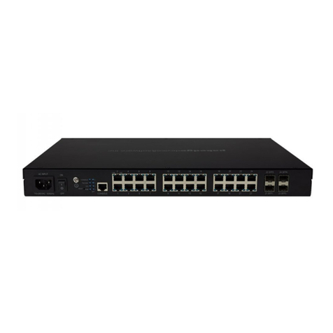
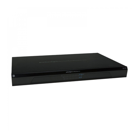
Pakedge S3L-24P Manual

S3L-24P
Layer 3 Lite Managed Switch
Hardware Installation Guide

Table of Contents
Intended readers ..................................................................................................................................................................................................... 1
Audience ............................................................................................................................................................................................................. 1
Other documentation ................................................................................................................................................................................... 1
Typographical conventions ....................................................................................................................................................................... 1
Style format conventions............................................................................................................................................................................ 1
Icon conventions............................................................................................................................................................................................. 1
Introduction .............................................................................................................................................................................................................. 2
Switch description......................................................................................................................................................................................... 2
Package contents .......................................................................................................................................................................................... 2
Switch components.............................................................................................................................................................................................. 3
Front panel components............................................................................................................................................................................ 3
LED indicators ...................................................................................................................................................................................... 3
Back panel components.............................................................................................................................................................................4
Side panel components .............................................................................................................................................................................. 5
Hardware installation...........................................................................................................................................................................................6
Installation guidelines ..................................................................................................................................................................................6
Installation into a rack .................................................................................................................................................................................6
Installing transceivers into the transceiver ports .......................................................................................................................... 8
Software features .................................................................................................................................................................................................. 9
Layer 2 features.............................................................................................................................................................................................. 9
Service access control............................................................................................................................................................................... 10
Layer 3 features............................................................................................................................................................................................ 10
Management features................................................................................................................................................................................ 10
Management information base (MIB)..................................................................................................................................................11
Technical specifications ....................................................................................................................................................................................13
Product specifications................................................................................................................................................................................13
Regulatory standards compliance .........................................................................................Error! Bookmark not defined.
Safety instructions ...............................................................................................................................................................................................14
Safety precautions .......................................................................................................................................................................................14
Electrical safety precautions...................................................................................................................................................................14
Rack-mount safety precautions ............................................................................................................................................................15
Ordering information ..........................................................................................................................................................................................15

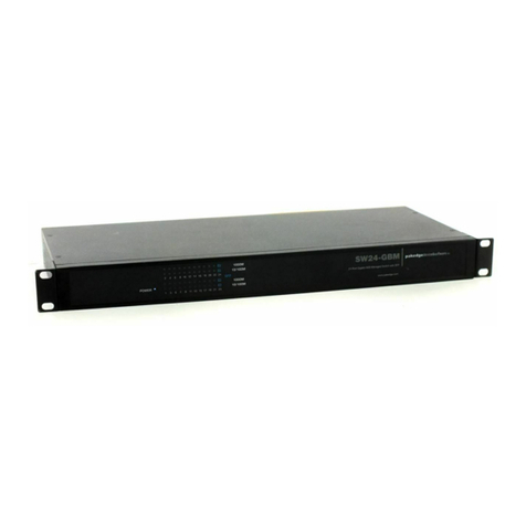
S3L-24P Layer 3 Lite Managed Switch Hardware Installation Guide
1
Intended readers
The S3L-24P Layer 3 Lite Managed Switch Hardware Installation Guide is based on the software release 1.00.
Audience
This guide is intended for network administrators and other IT networking professionals responsible for
installing and maintaining this switch. The S3L-24P will simply be referred to as the switch within this guide.
This guide is written in a way that assumes that users already have the experience and knowledge of
Ethernet and modern networking principles for Local Area Networks.
Other documentation
The documents below are a further source of information in regards to configuring and troubleshooting the
switch. All the documents are available from the product website. Other documents related to this switch
are:
•S3L-24P Layer 3 Lite Managed Switch Quick Start Guide.
•S3L-24P Layer 3 Lite Managed Switch Web User Interface Guide.
•S3L-24P Layer 3 Lite Managed Switch Command Line Interface Guide.
Typographical conventions
Throughout this document certain typographical conventions will be used to either emphasize information
or represent the features that this switch has to offer in a way that is understandable and useful to the
reader.
Style format conventions
The following style format conventions will be used in this document.
Convention
Description
Boldface Font
This convention is used to place emphasis on a keyword with a sentence used
in thi
s document.
Italic Font
This convention is used to indicate a variable. An example of a variable is file
names.
Icon conventions
The following icon conventions will be used in this document.
Note:
The note icon convention is used to highlight an important topic that could be useful to the reader.
Warning:
The warning icon convention is used to warn the reader of potential hazards that might result in
the
loss of data, potential damage to hardware or property, personal injury, or fatality. This warning will
also inform the reader how to avoid the problem.

S3L-24P Layer 3 Lite Managed Switch Hardware Installation Guide
2
Introduction
Switch description
The S3L-24P Layer 3 Lite Managed Switch is targeted for the deployment in Small-to-Medium Businesses
(SMB) providing 10 Gbps Ethernet wire-speed connections that can be used to uplink servers or to
interconnect switches within the LAN. For medium-to-large scale enterprise deployment, these switches
provide an excellent means to interconnect edge switches and core switches.
This switch features twenty-four 10/100/1000Mbps RJ45 copper Power over Ethernet (PoE) ports and four
1/10Gbps SFP+ module ports.
This switch supports the latest IEEE 802.3az Energy-Efficient Ethernet (EEE) standard to save power while
links are online or to notify selective ports automatically to enter into the standby mode when no traffic is
being transmitted or received.
Package contents
After purchasing this switch, the following items will be included in the package:
•One S3L-24P Switch.
•One Quick Start Guide (QSG).
•One AC power cord.
•One RS-232-to-RJ45 console cable.
•One pair of rack-mount brackets.
•Eight Phillips-head rack-mount bracket screws.
Note:
If any of the above mention items was not found inside the package contents of this switch or are
damaged in any way, contact the your reseller immediately.

S3L-24P Layer 3 Lite Managed Switch Hardware Installation Guide
3
Switch components
In this chapter we’ll discuss the physical components that can be found on the front, side, and back panels
of this switch.
Front panel components
The front panel of this switch features only LED indicators and no physical ports or buttons.
Figure 1 Front panel
LED indicators
The front and back panels of this switch feature the following LED indicators.
Figure 2 Front panel (LED Indicators)
Figure 3 Back panel (LED Indicators)
The following table lists the LED indicators available on the front and back panels of the switch.
LED Indicator Color Behavior Description
PWR, POWER
Blue Solid Light Power on
Off Power off. No power cable attached.
CON, CONSOLE
Blue Solid Light Console is on.
Off Console is off.
FAN
Blue Solid Light Diagnostics passed. Normal operation.
Red Solid Light Fan failure.
LINK/ACT/SPEED
Blue Solid Light Secure 10/100/1000 Mbps connection is active.
Blinking Packets transmitted and received.

S3L-24P Layer 3 Lite Managed Switch Hardware Installation Guide
4
LED Indicator Color Behavior Description
(Copper Ethernet
Ports)
Off No active connection or port disabled.
Amber Solid Light Secure 10/100/1000 Mbps connection is active and
power is being supplied to the device in the port.
Blinking Fast blinking: Packets transmitted and received.
Slow blinking: Error supplying power.
Off No active connection or port disabled.
Link/ACT/SPEED
(SPF+ Ports)
Blue Solid Light Secure 10 Gbps connection is active.
Blinking Packets transmitted and received.
Off No active connection or port disabled.
Amber Solid Light Secure 1 Gbps connection is active.
Blinking Packets transmitted and received.
Off No active connection or port disabled.
Back panel components
The back panel of this switch features the following components.
Figure 4 Back panel
The following table lists the physical ports and buttons available on the back panel of the switch.
Label Description
AC INPUT
One AC power receptacle (IEC 60320 C14).
One electrical grounding screw.
RESET
One factory reset button within pinhole. Press and hold this button for 3 to 5 seconds to
factory reset the switch.
CONSOLE
One out-of-band RJ45 console port
PORTS
Twenty-four copper PoE ports operating at 10/100/1000 Mbps.
Four SPF+ ports operating at 1/10 Gbps.
Connect one end of the AC power cord, included in the package, into the grounded electrical outlet at the
site and insert the other end of the AC power cord into the AC power receptacle. The switch will
automatically adjust the voltage supplied to the voltage needed as this power supply supports any voltage
power supply in the range from 100VAC to 240VAC at 50Hz to 60Hz.
Note:
For more information about supported SFP+ transceivers and transceiver installation, refer to the
Installing Transceivers into the Transceiver Ports section later on.

S3L-24P Layer 3 Lite Managed Switch Hardware Installation Guide
5
Side panel components
The side panels of this switch feature the following components.
Figure 5 Side panels
The following table lists the components found on the side panels of the switch.
•Four frontal rack-mount bracket screw holes on each side panel.
•Four rear rack-mount bracket screw holes on each side panel.
•Three ventilation fans.
•Heat dissipation vents on each side panel.
Note:
For more information about rack-mount installation, refer to Installation into a Rack.
This switch has a built-in temperature sensor that will measure the switch’s internal temperature and then
automatically adjust the speed of the fans to either high-speed or low-speed.
The table below describes at which temperature the fans will adjust to either high or low speed.
Fans Start-up Speed Adjust to High Speed Adjust to Low Speed
3 Low Speed Rises above 37°C Falls below 34°C

S3L-24P Layer 3 Lite Managed Switch Hardware Installation Guide
6
Hardware installation
Installation guidelines
This section will discuss the hardware installation guidelines that administrators must follow in order to
properly and safely install this switch into the appropriate environment.
Note:
Please read through the Safety Instructions chapter before starting any installation discussed in this
chapter.
Installation into a rack
This switch can be mounted in a standard 19"(1U) rack using the provided mounting brackets. The following
section will explain how to install the rack-mount brackets onto the switch and then mount the switch into a
standard 1U rack-mount unit.
The following parts will be used to install the switch into a rack-mount unit:
•One pair of either frontal or rear rack-mount brackets.
•Eight Phillips-head frontal or rear rack-mount bracket screws.
Additional equipment needed to install the switch into a rack-mount unit:
•One Phillips-head screwdriver. This screwdriver will be used for the rack-mount bracket screws
•One additional screwdriver. This screwdriver will be used for the rack-mount unit screws and its type
and size depends on the rack-mount unit screws being used.
•Four rack-mount unit screws. These screws will be used to attach the switch onto to the rack-mount
unit and are not included in the switch’s packaging as rack-mount units differ at each installation site.
The figure below illustrates how to install the frontal rack-mount bracketsonto the switch.
1. Place the switch on a flat horizontal surface.
2. Position the frontal rack-mount bracket over the screw holes on the side of the switch. The ears of
the bracket must be facing forward and outwards.
3. Use the frontal rack-mount screws and the Phillips-head screwdriver to fasten the bracket onto the
side of the switch.
4. Repeat steps 1 to 3 for the other frontal rack-mount bracket on the other side of the switch.
Figure 6: Front rack-mount bracket installation

S3L-24P Layer 3 Lite Managed Switch Hardware Installation Guide
7
The figure below illustrates how to complete the rack-mount installation.
5. Use the rack-mount unit screws and the additional screwdriver to fasten the frontal rack-mount
brackets onto the front of the rack-mount unit.
Figure 7 Installing switch in rack-mount unit
Note:
Make sure that there is adequate space around the switch to allow for proper air flow, ventilation, and
cooling.
Warning:
As a precaution, install the switch in a fairly cool and dry place within the acceptable temperature
and humidity operating ranges.

S3L-24P Layer 3 Lite Managed Switch Hardware Installation Guide
8
Installing transceivers into the transceiver ports
This switch supports 4 SPF+ 10 Gbps ports. SFP+ technology allows a smooth transition from 1 to 10 Gigabit
Ethernet infrastructures in switches. This switch supports both fiber and copper cabling solutions.
For low-cost cabling, copper-based 10 Gbps Twinaxial cables can be used, and for longer cable reaches,
Short-Reach (SR) optical transceivers are excellent. Connectivity can be established from the SFP+ ports to
10 Gigabit Ethernet switches or hosts using a fiber/copper cable that has an SFP+ transceiver on one end
and an SFP+ transceiver on the other end.
The figure below illustrates how to properly insert SFP+ transceivers into the switch’s SFP+ ports.
Figure 8: Installing transceivers into the transceiver ports
The following table lists the SFP+ transceiver types supported.
Part number Transceiver Speed Cable Distance
FM-1G-SM
SFP 1000BASE-
LX
Single-mode fiber (1310 nm) 20 km
FM-10G-SM
SFP+ 10GBASE-LR
Single-mode fiber (1310 nm) 10 km
FM-10G-DA-1M
SFP+ 10 Gbps Direct-attached-cable (passive)
1 meter

S3L-24P Layer 3 Lite Managed Switch Hardware Installation Guide
9
Software features
This switch supports the following software features.
Layer 2 features
Category Feature
Layer 2 table
•MAC address table (up to 16K entries).
•Dynamic address learning
•Layer 2 Unicast/Multicast
•Static configuration
•Layer 2 Multicast Entries (up to 511 entries)
Layer 2 functions
•Basic Ethernet port management
•Digital Diagnostic Monitoring (DDM)
•Traffic storm control
•Jumbo frames (up to 9Kbytes)
•Layer 2 Multicast control
•Static and dynamic link aggregation
○Up to 26 link aggregations and 8 member ports per group
•Mirroring (port mirroring, RSPAN, and ERSPAN)
•Quality of Service (bandwidth control, queues, and priority tag
remarking)
•VLAN (802.1Q VLAN, auto-voice VLAN, MAC-based VLAN, port-based
VLAN, private VLAN, protocol-based VLAN, and subnet VLAN)
•IEEE 802.1BA Audio Video Bridging (AVB)
○IEEE 802.1Q Multiple VLAN Registration Protocol (MVRP)
Supports 256 dynamic VLANs
○IEEE 802.1AS Timing and Synchronization for Time-Sensitive Applications in
Bridged Local Area Networks
○IEEE 802.1Qat Stream Reservation Protocol (SRP)
Supports up to 75 streams
○IEEE 802.1Qav Forwarding and Queuing Enhancements for Time-Sensitive
Streams (FQTSS)
Supports Class A and Class B
Layer 2 protocols
•Spanning Tree Protocol (STP, RSTP, and MSTP)
•Local loop detection and prevention
•IGMP snooping (IGMPv1, IGMPv2, and IGMPv3 snooping)
•Multicast VLAN Registration (MVR)
•Port-based IGMP snooping fast leave

S3L-24P Layer 3 Lite Managed Switch Hardware Installation Guide
10
Category Feature
•IGMP snooping proxy mode and transparent mode
•IGMP query
•Link Layer Discovery Protocol (LLDP)
•Link Layer Discovery Protocol Media Endpoint Discovery extension
(LLDP-MED)
Service access control
Category Feature
Service access control
•DHCP Snooping
•Dynamic ARP inspection
•IP Source Guard (IPSG)
•IEEE 802.1X (Authenticator role, dynamic VLAN assignment, EAP, TLS,
TTLS, MD5 authentication, single/multiple host mode, time-based
802.1X sessions, RADIUS authentication, and unauthenticated
VLAN/guest VLAN.
•DHCP server filtering
Layer 3 features
Category Feature
Layer 3 table
•IP optimized host prefixes (up to 512 IPv4 or 256 IPv6 entries)
•IP routing entries (up to 64 IPv4 or 16 IPv6 entries)
•IP multicast groups (up to 63 IPv4 multicast groups)
Routing
•Static IPv4/IPv6 routes
•ICMPv4 and ICMPv6
•IPv4 Address Resolution Protocol (ARP)
•IPv6 Neighbor Discovery (ND)
•Router interface (up to 16 router interfaces)
•IP multinetting
Multicast routing
protocol
•Internet Group Management Protocol (IGMPv1, IGMPv2 and IGMPv3)
Management features
Category
Feature
Management features
•Access Control Lists (ACL)
•Command Line Interface (CLI)

S3L-24P Layer 3 Lite Managed Switch Hardware Installation Guide
11
Category Feature
•Dos attack prevention
•DHCP client (IPv4/IPv6)
•DHCP relay (with Option 82)
•DHCP Server (IPv4)
○Supports 8 default routers, 8 WINS servers, 1024 address pools, and 1024
clients
•Event log (command and system logs)
•File system (extract/restore system configuration, extract/upgrade
firmware)
•IPv4/IPv6 dual stacks (router mode and IPv4/IPv6 network
management interface)
•Ping command
•RADIUS server and client
•TACACS+ server and client
•Sampled Flow (sFlow) version 5
○Supports 4 receivers, 32 samplers, and 384 pollers
○The minimum granularity of sampling is 256
•Simple Network Management Protocol (SNMPv1, SNMPv2c and
SNMPv3)
•Simple Network Time Protocol (SNTP)
•Secure Shell (SSHv2)
•Secure Sockets Layer (SSLv2 and SSLv3)
•Static ARP table configuration
•System monitoring (environmental monitoring, system resources
information, and system log)
•Telnet server (up to 8 simultaneous IPv4/IPv6 management sessions)
•Traceroute command
•Trusted host list
•User account management (privileges, password encryption, user
account and password recovery)
•Web-based User Interface (Web UI)
Management information base (MIB)
Category
Feature
Layer 2 MIBs
•IEEE8021-MSTP-MIB, IEEE8021-Q-BRIDGE-MIB, IEEE8023-LAG-MIB,
LLDP-EXT-DOT1-V2-MIB, LLDP-EXT-DOT3-V2-MIB, LLDP-V2-MIB,
LLDP-EXT-MED-MIB, P-BRIDGE-MIB, Q-BRIDGE-MIB, IEEE8021-AS-MIB,
IEEE8021-SRP-MIB, IEEE8021-FQTSS-MIB
Layer 3 MIBs
•IP-FORWARD-MIB, IPMCAST-MIB, IP-MIB, MGMD-STD-MIB

S3L-24P Layer 3 Lite Managed Switch Hardware Installation Guide
12
Category Feature
Management MIBs
•DISMAN-PING-MIB, DISMAN-TRACEROUTE-MIB, EtherLike-MIB, IF-MIB,
RMON-MIB, SNMP-COMMUNITY-MIB, SNMP-FRAMEWORK-MIB, SNMP-
MPD-MIB, SNMP-NOTIFICATION-MIB, SNMP-TARGET-MIB, SNMP-
USER-BASED-SM-MIB, SNMPv2-MIB, SNMP-VIEW-BASED-ACM-MIB,
SFLOW-MIB
Private MIBs
•
L2 application MIBs
○PAKEDGE-BANDWIDTH-CONTROL-MIB, PAKEDGE-L2FDB-MIB, PAKEDGE-
LACP-EXT-MIB, PAKEDGE-MGMD-SNOOPING-MIB, PAKEDGE-PRIVATE-
VLAN-MIB, PAKEDGE-STORM-CONTROL-MIB, PAKEDGE-SWITCHPORT-MIB,
PAKEDGE-VLAN-MIB, PAKEDGE-VOICE-VLAN-MIB, PAKEDGE-MVR-MIB
•
IP application MIBs
○PAKEDGE-DHCP4-CLIENT-MIB, PAKEDGE-DHCP6-CLIENT-MIB, PAKEDGE-
DHCP6-RELAY-MIB, PAKEDGE-DHCP-FILTER-MIB, PAKEDGE-DHCP-
SNOOPING-MIB, PAKEDGE-DYNAMIC-ARP-INSPECTION-MIB, PAKEDGE-
DOS-PREVENT-MIB, PAKEDGE-MGMD-MIB, PAKEDGE-DHCP-RELAY-MIB,
PAKEDGE-SSH-MIB, PAKEDGE-TIME-CONFIGURATION-MIB, PAKEDGE-
VLAN-INTERFACE-MIB
•
Management MIBs
○PAKEDGE-ACCESS-MANAGEMENT-MIB, PAKEDGE-DDM-MIB, PAKEDGE-
ERROR-DISABLE-MIB, PAKEDGE-LOOPDETECT-MIB, PAKEDGE-PACKET-
MONITORING-MIB, PAKEDGE-SYSLOG-MIB, PAKEDGE-SYSTEM-FILE-MIB,
PAKEDGE-SYSTEM-MONITORING-MIB, PAKEDGE-CFG-CHANGE-NTFY-MIB,
PAKEDGE-POWER-SAVING-MIB, PAKEDGE-DHCP-SERVER-IPV4-MIB
Note: For more information about how to configure and monitor the software features of this switch using
the Command Line Interface, refer to the S3L-24P Layer 3 Lite Managed Switch Command Line
Interface Guide.
Note:
For more information about how to configure and monitor the software features of this switch using
the Web User Interface, refer to the S3L-24P Layer 3 Lite Managed Switch Web User Interface Guide.

NK-1 Wireless Controller User Guide
13
Technical specifications
Product specifications
The following tables list the product specifications for this switch.
Category Specification Description
Physical
Form factor
1 RU fixed form factor
Physical ports
24 copper PoE ports (10/100/1000 Mbps)
4 SFP+ module ports (1/10 Gbps)
Performance
Switching capacity
128 Gbps
Forwarding rate
95.23 Mpps
Maximum transmission units
9 Kbytes (jumbo frames)
Scalability
Number of MAC addresses
16,384 (max)
Buffer size
1.5 MB shared
Flash memory size
64 MB
Power over
Ethernet (PoE)
PoE budget
370 watts
IEEE 802.3af (PoE) support
Yes (supplies 15.4 watts per port)
IEEE 802.3at (PoE+) support
Yes (supplies 30 watts per port)
Automatic PD discovery
Yes (will supply power immediately if PD device was
detected.)
PoE safety
Automatically disable individual ports when electrical
current is over 600mA or when electrical short
occurred.
Power
AC power supply
Input Voltage
100VAC to 240VAC
Frequency
50 Hz to 60 Hz
Efficiency
85% to 88%
Maximum power
consumption
430 watts
•370 watts with full PoE load and 30 watts for
guard band.
•30 watts with full non-PoE load.
Maximum heat dissipation
1541 BTU/hr
Cooling
Number of fan modules
3
Fan speeds
Automatic high and low speed depending on internal
temperature.
Noise factor
Maximum fan noise factor
54 dBA
Environment
Dimensions
44mm (H) x 440mm (W) x 210mm (D)
Weight
5.0 kg

NK-1 Wireless Controller User Guide
14
Category Specification Description
Operating temperature
0°C to 45°C (32°F to 113°F)
Storage temperature
-20°C to 70°C (-4°F to 158°F)
Operating relative humidity
10% to 90% (non-condensing)
Storage relative humidity
0% to 95% (non-condensing)
Altitude
0 to 2,000 meters (0 to 6,562 feet)
Safety instructions
The following sections provide safety precautions to follow when installing the switch.
Safety precautions
For your protection, observe the following safety precautions when setting up your equipment:
•Follow all cautions and instructions marked on the equipment.
•Only trained and qualified personnel are allowed to install or to replace this equipment.
•Never push objects of any kind through openings in the equipment. Dangerous voltages
may be present. Conductive foreign objects could produce a short circuit that could cause
fire, electric shock, or damage to your equipment.
•This product is intended for restricted access whereby access is controlled through the use
of a means of security (for example, key, lock, tool, badge access) and personnel
authorized for access have been instructed on the reasons for the restrictions and any
precautions that need to be taken.
•Remove all metal jewelry, such as rings and watches, before installing or removing the
device.
•Do not look directly at the fiber optic cable ends or inspect the cable ends with an optical
lens.
•Do not install in direct sunlight, or a damp or dusty place.
•Do not expose the device to moisture or water.
•Disconnect all power supply cords before servicing.
Electrical safety precautions
For your protection, observe the following electrical safety precautions when setting up your
equipment:
•Ensure that the voltage and frequency of your power source match the voltage and
frequency inscribed on the equipment’s electrical rating label.
•This switch is designed to work with power systems having a grounded neutral. To reduce
the risk of electric shock, do not plug the switch into any other type of power system.
Contact your facilities manager or a qualified electrician if you are not sure what type of
power is supplied to your building.
•Not all power cords have the same current ratings. Do not use the power cord provided
with your equipment for any other products or use. Household extension cords do not have
overload protection and are not meant for use with these switches. Do not use household
extension cords with this product.

NK-1 Wireless Controller User Guide
15
•To prevent electric shock, do not remove the cover of this product. There are no user-
serviceable parts inside. This unit contains hazardous voltages and should only be opened
by a trained and qualified technician.
•Do not work on equipment or cables during periods of lightning activity.
•Check to see if there are any exposed copper strands coming from the installed wire. When
this installation is done correctly there should be no exposed copper wire strands
extending from the terminal block. Any exposed wiring can conduct harmful levels of
electricity to persons touching the wires.
•The power source for the device should be located near the unit and should be easily
accessible.
•Circuit Overloading: Consideration should be given to the connection of the equipment to
the supply circuit and the effect that overloading of circuits might have on overcurrent
protection and supply wiring. Appropriate consideration of equipment nameplate ratings
should be used when addressing this concern.
Rack-mount safety precautions
For your protection, observe the following rack-mount safety precautions when setting up your
equipment:
•Elevated operating ambient - If installed in a closed or multi-unit rack assembly, the
operating ambient temperature of the rack environment may be greater than room
ambient. Therefore, consideration should be given to installing the equipment in an
environment compatible with the maximum ambient temperature (Tma) specified by the
manufacturer.
•Reduced air flow - Installation of the equipment in a rack should be such that the amount
of air flow required for safe operation of the equipment is not compromised.
•Mechanical loading - Mounting of the equipment in the rack should be such that a
hazardous condition is not achieved due to uneven mechanical loading.
•Circuit overloading - Consideration should be given to the connection of the equipment to
the supply circuit and the effect that overloading of the circuits might have on overcurrent
protection and supply wiring. Appropriate consideration of equipment nameplate ratings
should be used when addressing this concern.
•Reliable earthing - Reliable earthing of rack-mounted equipment should be maintained.
Particular attention should be given to supply connections other than direct connections to
the branch circuit (for example, use of power strips).
•For safety, equipment should always be loaded from the bottom up. That is, install the
equipment that will be mounted in the lowest part of the rack first, then the next higher
systems, etc.
•To prevent the rack from tipping during equipment installation, the anti-tilt bar on the rack
must be deployed.
•The mounting brackets provided must be used to securely mount the device in a rack-
mount unit.
Ordering information
Part number Description
S3L-24P
S3L-24P Layer 3 Lite Managed Switch.
24 copper PoE ports with 10/100/1000Mbps wire-speeds.
4 SFP+ module ports with 1/10 Gbps wire-speeds.

11734 Election Road
Draper, UT 84020
U.S.A
For technical help:
www.pakedge.com
support@pakedge.com
(650) 385-8703
For non-technical questions:
customerservice@pakedge.com
(650) 385-8701
Warranty information:
pkdge.co/warranty
Regulatory information:
pakedge.com/regulatory
Copyright ©2017, Control4 Corporation. All rights reserved. Control4, the Control4 logo,
Pakedge, and BakPak are registered trademarks or trademarks of Control4 Corporation or its
subsidiaries in the United States and/or other countries. All other names and brands may be
claimed as the property of their respective owners. All specifications subject to change
without notice.
DOC-003339-A 2017-10-03 MS
Table of contents
Other Pakedge Switch manuals

Pakedge
Pakedge MS Series User manual

Pakedge
Pakedge MS-1212 User manual

Pakedge
Pakedge S3 Series User manual

Pakedge
Pakedge SX-24P User manual

Pakedge
Pakedge SX-8P User manual

Pakedge
Pakedge SX-24P16 User manual

Pakedge
Pakedge SX-8P User manual

Pakedge
Pakedge SK-24 User manual

Pakedge
Pakedge SE-18 User manual

Pakedge
Pakedge SW8-GBP User manual