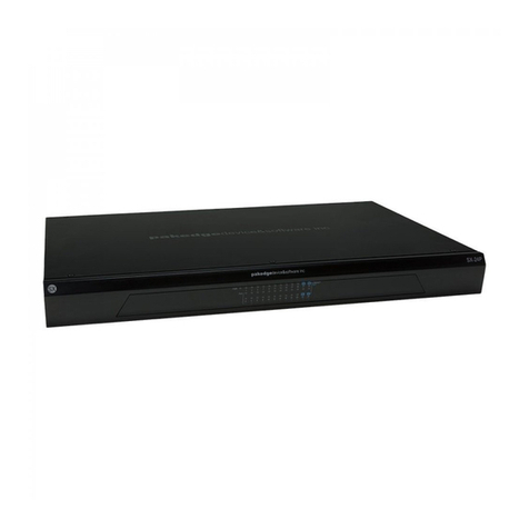
Pakedge SK-24 User manual

QUICK START GUIDE
SK-24 / SK-24F
Fully Managed Gigabit Switch with 24 Front or Rear Facing Ports
Version 1.0
pakedgedevice&software inc

2
Contents
Switch Overview 3
Preparing to Install the Switch 4
Installation 4
Logging Into the Switch 5
Changing the IP Address of the Switch 6
Pakedge Zone & VLAN Setup 7
Manually Conguring VLANs 8
Console Into the Switch 10
Resetting IP address through the console 11
Factory defaulting through the console 11

3
The SK Series switches are fully managed gigabit switches, designed to address a wide range of
networking needs. The SK Series switches are encased in AV like housings to appeal to customers
demand for aesthetics.
The following chart denes the features of the SK-24/SK-24F.
Port Speeds 10/100/1000 mbps SFP Yes
Console Port Yes SFP Ports 2
Web GUI Yes Shared SFP No
Ethernet Ports 24
Switch Overview

4
Installing the SK-24 is similar to installing any other Pakedge switch. If you have installed a man-
aged switch before, the process will be very similar. The GUI for the SK-24 and SK-24F switches will
be the same so the conguration steps discussed later in this quick start guide can be used on any
of the switches.
Tools required:
• Philips Screwdriver (if using rack-mount brackets).
• Computer with Ethernet interface and a modern web browser.
• Optional: An integrated “DB-9” port or USB-To-DB9 adapter may be necessary in order to
use the console interface.
• Ethernet Cable.
Preparing to Install the Switch
Installation
1. Remove the switch from the box.
2. Optional: If mounting the switch in a standard 19” AV rack, attach the rack-mounting
brackets that come with the switch to the sides. If not rack-mounting, ensure that the
switch is physically mounted near power and network connections (i.e, backbone switch or
rewall/router).
3. Connect power to the device.
4. Connect an Ethernet cable from your computer to any LAN port on the switch.
5. You are now ready to congure the switch with an IP address in your network range.
5
1. Connect the SK switch to a power source. The PWR LED will light up and the fans will start.
2. Connect a PC or laptop to any LAN port on the switch.
3. Congure the PC with a static IP address of 192.168.1.10 and subnet mask of
255.255.255.0 (Default Gateway and DNS can be left blank) and then open any browser.
4. In the browser, enter the switch’s default IP address of 192.168.1.205 into the Address Bar
and press <ENTER>.
5. A web page will appear asking you for a Username and Password. The default username is
pakedge and the password is pakedges.
6. Once you have logged into the switch you will have access to the GUI and will be able to
make any changes you wish. The following is an example of the switch dashboard.
Logging Into the Switch

6
1. There are two steps to conguring the the IP Address settings on the switch. From the
Dashboard click “System” and then go to “System Settings > Basic Settings”.
2. In this section you can enter the switch IP address in the box next to “IP Address”. By
default the switch IP is 192.168.1.205. You will also need to enter the “Subnet Mask” and
“Gateway” settings for your network. By default on a Pakedge network subnet mask is
255.255.255.0 and the Gateway will be 192.168.1.99.
3. Click on “Apply” at the bottom of the page and the switch will be updated with the new IP
settings. If the IP address you have changed the switch to is in the same IP subnet range
you will be redirected automatically. Otherwise you will need to update your computers IP
settings to match the new IP of the switch in order to access it again.
Changing the IP Address of the Switch

7
Pakedge Zone & VLAN Setup
New to the SK Series switches are the Pakedge Zones. Pakedge Zones provide a simple way to
congure the switch to match the specialized VLAN settings of a Pakedge network.
This new VLAN conguration page allows for very quick implmentation of VLAN settings across all
ports of the switch.

8
1. To manually add and congure VLAN settings go to VLAN>Conguration>Advanced.
2. Under the “Manage VLANs” section you can click “Add” to input a new VLAN ID number
and name.
Then click “Apply” to save that VLAN to the switch. VLAN ID’s 1 - 6 are color coded to
match the Pakedge Zones these are used for.
3. To congure ports as dierent VLANs, use the “Port Assignments” section.
Manually Conguring VLANs

9
4. To set ports with the ability to only access a single VLAN, click the VLAN you want to use
under “Access”.
Then click on the ports above you wish to set with that VLAN. Once you have the ports
you want selected, click Apply at the bottom of the page to save those settings.
5. To set ports in Hybrid mode (one Default VLAN and multiple Tagged VLANs), rst click the
“+” symbol under “Hybrid”. You will then be in the Hybrid prole conguration mode.
6. First select the Untagged Default VLAN to be used on the port (normally VLAN1).
7. Next select one or more other VLANs to be used for tagged VLAN trac.
8. Lastly, click on the box under “Assigned Port” and then click on one of the ports above to
set this prole on a switch port v
9. Once the changes have been made you can click “Apply” at the bottom of the page to
save the settings.

10
The SX Series switches have a console port to serve as a back door entrance to the switch. This
can be benecial in case the switch is not functioning properly or if the incorrect IP address was
congured. To console into the switch please take the following steps:
1. Connect the console cable to the console port on the back of the switch and then connect
the other end to your computer. You may use a USB to serial adapter in case your com-
puter doesn’t have a serial port. You will also need to have either PuTTY or Terra Term to
connect to the switch’s command line console.
2. Open PuTTY or Terra Term and enter the COM port that your computer is using and then
set the following settings:
Baud Rate: 9600
Character Size: 8
Parity Code: None
Stop Bits: 1
Flow Control: None
The following is an example if you are using putty:
3. If you are using putty you need to go to Session on the left hand side and select Serial for
the connection type and then click open to actually initiate the console session.
4. Once the connection is established you can type enable and enter the switch password
pakedges to view and edit switch settings.
5. You now have console access into the switch.
Console Into the Switch

11
You can reset the IP address of the switch through the console. This can be helpful in case of miss-
conguration. To do this you will rst need to console into the switch as previously described and
then take the following steps:
1. Type show interface 1 and press enter to see the current IP address
2. Type congure terminal and press enter
3. Type interface vlan 1 and enter to edit the VLAN1 interface
4. Type ip address 192.168.1.205 255.255.255.0 and press enter
5. The switch should now be accessible on its default IP address
Resetting IP address through the console
Factory defaulting through the console
You can factory default the switch through console in case it is not functioning prop-
erly. To do this you will rst need to console into the switch as previously described
and take the following steps:
1. Type erase startup-cong and press enter
2. Type reload and press enter
3. Type yes and press enter to use defaulted cong at startup
4. Type yes to allow the switch to reboot
5. The switch will now reboot and come back up at default settings

pakedgedevice&software inc
3847 Breakwater Avenue Hayward,CA 94545
Main: 650-385-8700 Fax: 650.685.5520
www.pakedge.com
sales@Pakedge.com
Technical Support
Please visit our website for up to date support information.
Web: www.pakedge.com
FCC Statement:
This equipment has been tested and found to comply with the limits for a Class A digital device, pursuant to
part 15 of the FCC Rules. These limits are designed to provide reasonable protection against harmful inter-
ference when the equipment is operated in commercial environment. This equipment generates, uses, and
can radiate radio frequency energy and, if not installed and used in accordance with the instruction manual,
may cause harmful interference to radio communications. Operation of this equipment in a residential area
is likely to cause harmful interference in which case the user will be required to correct the interference at
his own expense.
FCC Caution: Any changes or modications not expressly approved by the party responsible for compliance
could void the user’s authority to operate this equipment.
This device complies with part 15 of the FCC Rules.
Operation is subject to the following two conditions:
(1)This device may not cause harmful interference, and(2) this device must accept any interference received,
including interference that may cause undesired operation. The manufacturer is not responsible for any radio
or TV interference caused by unauthorized modications to this equipment.
© Pakedge Device & Software Inc. 2015 – All Rights Reserved
This manual suits for next models
1
Table of contents
Other Pakedge Switch manuals

Pakedge
Pakedge SX-8P User manual

Pakedge
Pakedge SE-8 User manual

Pakedge
Pakedge SX-24P User manual

Pakedge
Pakedge MS Series User manual

Pakedge
Pakedge SW8-GBP User manual

Pakedge
Pakedge S3L-24P Manual

Pakedge
Pakedge SX-24P16 User manual

Pakedge
Pakedge MS-1212 User manual

Pakedge
Pakedge SE-18 User manual

Pakedge
Pakedge S3 Series User manual