Pakedge SW24-GBM User manual

SW24-GBM
Enterprise-Class, 24-Port Fully Managed Switch
Quick Installation Guide – Version 1.1

Table of Contents
Introduction .................................................................................................................................................................................................... 2
Quick Switch Overview ............................................................................................................................................................................... 2
Preparing to Install the Switch.......................................................................................................................................................................5
Installation ..................................................................................................................................................................................................... 5
Configuration ................................................................................................................................................................................................ 6
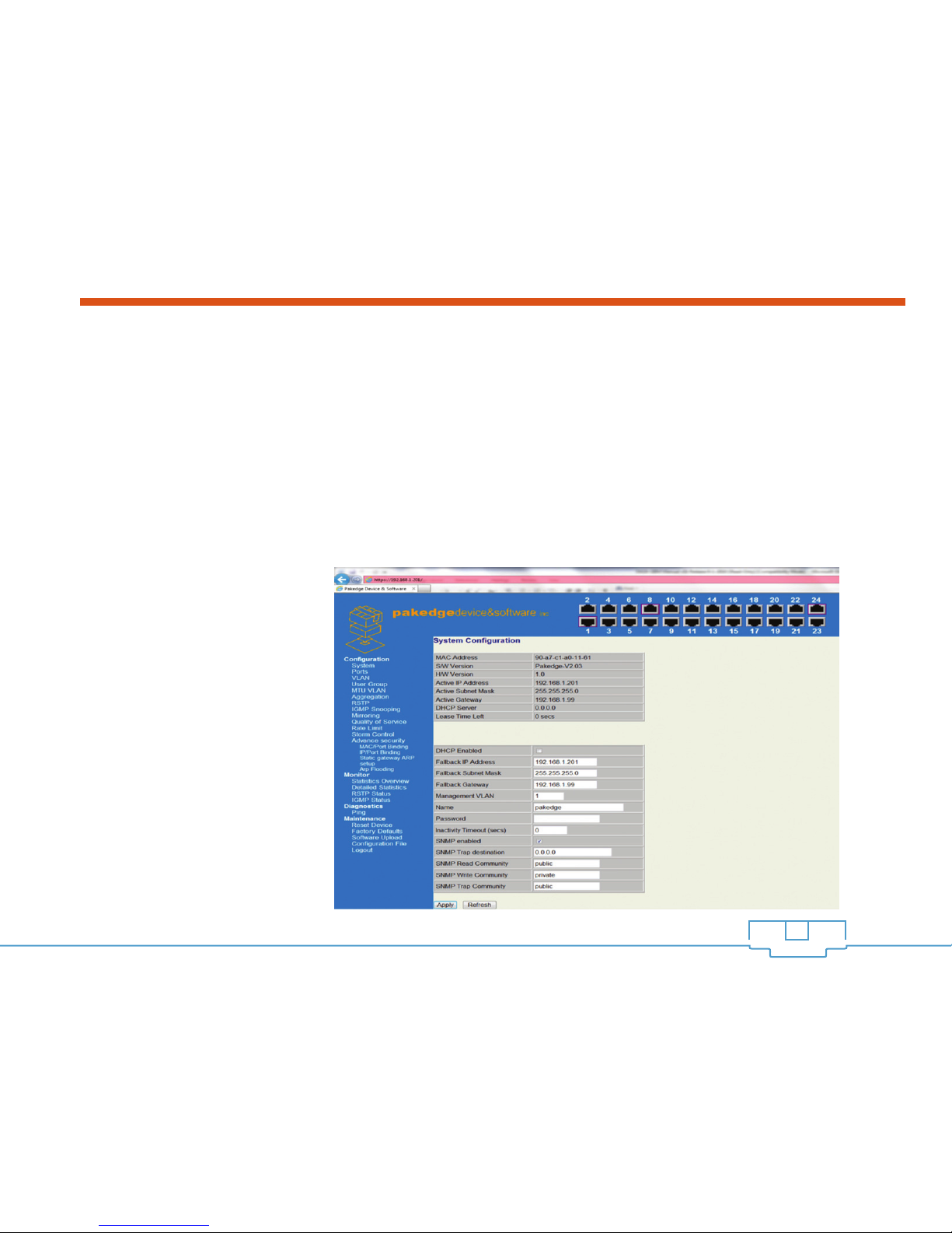
Configuring the Switch Using the Web Interface .....................................................................................................................................6
To Reset the IP Address of the Switch using the Supplied Console cable ............................................................................................ 9
Troubleshooting & Support ......................................................................................................................................................................... 11
Table of Figures
Figure 1: SW24-GBM Front Panel ..............................................................................................................................................................3
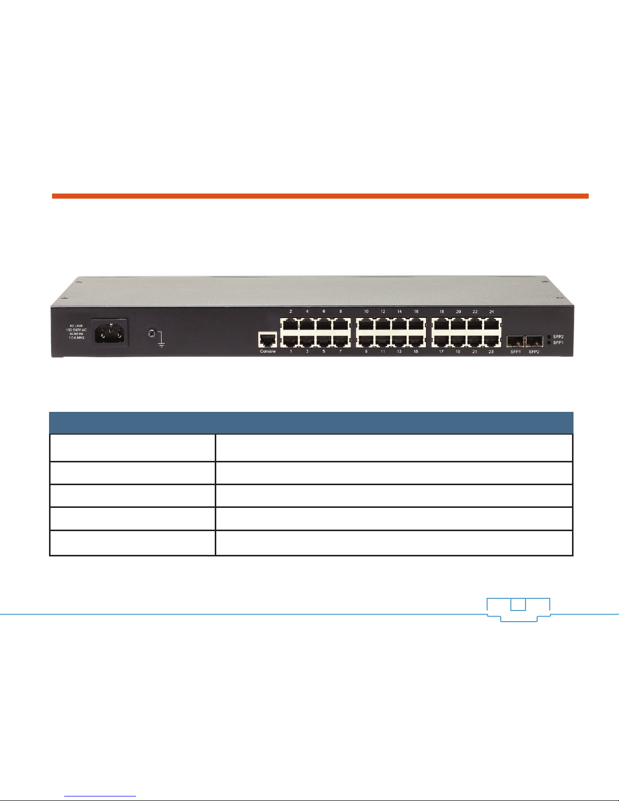
Figure 2: Rear Panel of the SW24-GBM .................................................................................................................................................. 4
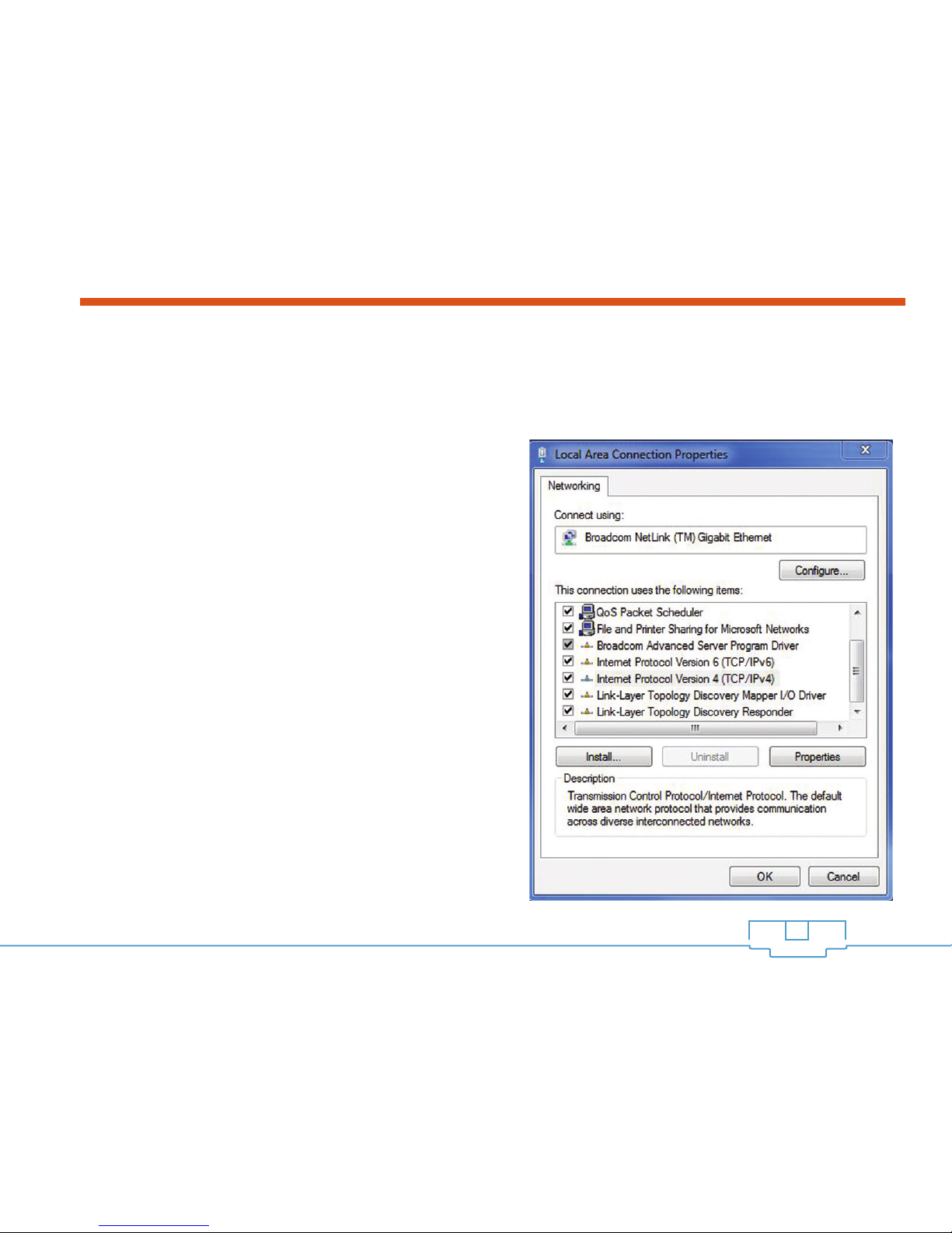
Figure 3: Local Area Connection Properties ............................................................................................................................................. 6
Figure 4: TCP/IP Properties ..........................................................................................................................................................................7
Figure 5: Console Connection in Terminal Window ............................................................................................................................... 10
1
SW24-GBM QUICK INSTALLATION GUIDE

SW24-GBM QUICK INSTALLATION GUIDE
1. INTRODUCTION
This guide has been written to allow you to get up and running quickly with the SW24-GBM Pakedge switch
with a few assumptions in mind:
a. You have a working knowledge of networking hardware configuration
b. You have a working knowledge of PC operations
QUICK SWITCH OVERVIEW
The SW24-GBM includes 24 10/100/1000 ports. Additionally, it includes 2 Gigabit SFP interfaces and a
console interface. The features of the standard ports are shown in Table 1.
2
Table 1: Switch Port Features
Port name Features
Giga Ethernet interfaces Speed:10/100/1000M auto-sense; cable: MDI/MDIX, UTP (RJ45)
interface with LINK/ACT, 1000 Mbps indicator
SPF Speed: 10/100/1000M auto-sense; cable: Fiber Optic
Console interface Speed: 9600bps, RJ45 interface

SW24-GBM QUICK INSTALLATION GUIDE
The Front Panel ofthe SW24-GBM (shown in Figure 1) has several LEDs, displaying the status ofthe switch
ports.
3
Figure 1: SW24-GBM Front Panel
Table 2: LED Descriptions
Label Function Description
PWR Power indicator light When lit, indicates that unit has power.
10/100M Link and Activity Indicator of each port Indicator lights when Ethernet link is normal.
Indicator blinks when data is sent or received.
1000M Speed Indicator of Giga port Indicator is lit when the port is in 1000M.
Indicator is not lit when port is in 10/100M.

SW24-GBM QUICK INSTALLATION GUIDE 4
The rear panel (Figure 2) is where the ports and other equipment connections are located.
Table 3 describes each port and their function.
Figure 2: Rear Panel of the SW24-GBM
Table 3: Description of the Rear Panel of the SW24-GBM from left to right
Name Explanation
AC connector AC110 ~ 260V
Grounding bar Please ground as needed.
CONSOLE Implement Switch Local management.
24 10/100/1000M Ports Implement 10/100/1000M Ethernet signal transformation.
2 SFP Ports Implement 10/100/1000M Ethernet signal transformation.

SW24-GBM QUICK INSTALLATION GUIDE
PREPARING TO INSTALL THE SWITCH
Installing the SW24-GBM is similar to installing any other Ethernet Switch. If you have installed an Ethernet
switch before, the process is very similar.
Tools Required:
• PC or Laptop with Ethernet Interface and a web browser (an integrated DB-9 port or USB to Serial
adapter may be necessary if you would like to use the console interface)
• Ethernet Cable (RJ45 Cable)
• Phillips Screwdriver (if using Rack-mount Brackets)
INSTALLATION
1. Open Box and Remove Unit
a. OPTIONAL: If mounting the switch in a standard 19” AV rack, attach the rack mounting brackets that
are included with the SW24-GBM to the sides of the unit
b. Physically mount the SW24-GBM switch near the power and network connections (i.e. backbone switch
or firewall/router)
2. Connect to the SW24-GBM switch to a power source
3. Connect your computer to any of the available ports on the SW24-GBM switch
4. Configure the switch to an IP address that matches your network. Configuration process is described in the
following sections.
5

SW24-GBM QUICK INSTALLATION GUIDE
CONFIGURATION
There are two ways to complete the initial configuration of the SW24-GBM switch – either by using the
standard IP address and a web browser or the console cable and a terminal emulation program such as
PuTTY or HyperTerminal.
CONFIGURING THE SWITCH USING THE WEB
INTERFACE
1. First you need to configure the PC with IP address
192.168.1.10, and subnet mask 255.255.255.0
by going to the Windows Control Panel, double-
click Network Connections and double-click the
connection of your Network Interface Card (NIC).
The Local Area Connection Properties dialog
appears:
6
Figure 3:
Local Area Connection Properties

SW24-GBM QUICK INSTALLATION GUIDE 7
2. Select Internet Protocol (TCP/IP) and click Properties. The Internet Protocol (TCP/IP) dialog appears
where you can configure the TCP/IP settings of your PC.
Figure 4:
TCP/IP Properties

SW24-GBM QUICK INSTALLATION GUIDE 8
3. Select “Use the following IP Address” and manually type in the IP address and subnet mask into the
provided boxes, as in Figure 4. (Be sure the IP address and subnet mask are on the same subnet as the
SW24-GBM.)
4. Click OK to close the dialog, and then click OK to close the Local Area Connection Properties dialog.
5. Now open a web browser (Internet Explorer, Mozilla and Chrome browsers all work for configuring the
SW24-GBM, but Internet Explorer is preferred)
6. Enter the switch’s default IP address: 192.168.1.201 into the Address Bar and press <ENTER>.
7. The default password is blank. Simply click “Apply” to be logged into the web administration portal.
8. In the web administration portal, you will be able to configure, update and reset the SW24-GBM.
Figure 5:
SW24-GBM Web Interface
PLEASE NOTE: Once you
have logged in, you may
use the web interface (Figure
5) to configure the switch
and customize it for your
environment. You may also
refer to the complete product
manual on our website for
advanced configurations.

SW24-GBM QUICK INSTALLATION GUIDE 9
TO RESET THE IP ADDRESS OF THE SWITCH USING THE SUPPLIED CONSOLE CABLE
Configuring the switch using the console cable method is more involved. However, this method is helpful if
the Ethernet interfaces are not functioning properly, or the incorrect IP address was accidentally set on the
switch rendering it inaccessible through the web interface.
1. In order to connect to the switch, you must first have a PC with a DB-9 serial port or a USB-to-Serial
adapter. In addition, you need to use software such as HyperTerminal or PuTTY (available for free on the
Internet) to connect to the switch’s command line console.
2. Once you have located the serial port on your computer, plug the supplied Console Cable into the
computer and the switch (DB9 end to the computer and RJ-45 end into the switch’s “Console” port).
3. When your physical connection is set up, configure your terminal software to connect to the switch.
You should already know which COM port your PC uses for a serial port (COM1 or COM2 on most
computers, COM1 through COM10 if using a USB-to-serial adapter). In addition to the COM port #,
Table 4 shows the necessary settings that must be set in the terminal communications software in order to
make a successful connection.
Baud Rate 9600
Character Size 8
Parity Code None
Stop Bits 1
Flow Control None
Table 4:
Default Serial Port Settings for
Console Connection

SW24-GBM QUICK INSTALLATION GUIDE 10
TO RESET THE IP ADDRESS OF THE SWITCH USING THE SUPPLIED CONSOLE CABLE (continued)
Once the connection is established through the console cable, you will be able to configure the switch
through the Terminal Program. To configure your switch back to the default network IP address of
192.168.1.201 with a subnet of 255.255.255.0, continue with the following steps:
4. Once the terminal screen pops up you will see a screen similar to the one in Figure 5. Once this
screen appears, hit enter (there is no password).
5. Type: IP Setup 192.168.1.201 255.255.255.0 192.168.1.99 <ENTER>
6. Your switch should now be
accessible from the network.
Figure 5:
Console Connection in
Terminal Window

SW24-GBM QUICK INSTALLATION GUIDE11
TROUBLE SHOOTING & SUPPORT
If you are unable to get the SW24-GBM switch functional using thesesteps, you can refer to the full manual
on our website or contact the Technical Support team for help.
CONTACTINFORMATION:
Website:
www.pakedge.com
Email: support@pakedge.com
Phone: 650.385.8703
Please be prepared to provide your product’s modeland serial number when contacting Pakedge Support.
Your model and serial numbers areprinted on a label located on the electronic housing.
© Pakedge Device & Software Inc. 2012 – All Rights Reserved
1163 Triton Drive
Foster City, CA 94404
U.S.A.
Table of contents
Other Pakedge Switch manuals

Pakedge
Pakedge S3L-24P Manual

Pakedge
Pakedge MS-1212 User manual

Pakedge
Pakedge SE-8 User manual

Pakedge
Pakedge SX-8P User manual

Pakedge
Pakedge SK-24 User manual

Pakedge
Pakedge SX-24P16 User manual

Pakedge
Pakedge SX-8P User manual

Pakedge
Pakedge MS Series User manual

Pakedge
Pakedge SW8-GBP User manual

Pakedge
Pakedge S3 Series User manual