Paladin Tools 1112 AM Operating manual

Support: 1.800.272.8665
Int’l Phone: 001.804.550.1121
E-Mail: paladin@paladin-tools.com
Web: www.paladin-tools.com
Tool Operation and Use Guide

Paladin Tools®1
1112 AM 12 Twisted Pair Cable
Stripper
To cut cable:
1. Install the wire or cable into the circular hole
closest to the finger loop.
2. Grip the tool & squeeze the top handle down until
the cable is cut.
To strip wire & cable:
1. Adjust the blade depth screw to the desired cutting
depth.
2. Place wire/cable into the smallest hole it can fit
into.
3. Put your finger into the finger loop & spin the tool
clockwise around the cable 3 to 6 times. Do not
squeeze the top handle down when spinning.
4. Open the handle & remove the cable. Pull the
stripped insulation off the cable.
Note: The AM 12 is especially useful for 4-pair UTP
& STP cables.
Cutting cable Stripping cable
Blade depth
adjustment screw
Stripping length
gauge
Strip/cut up to 12 AWG (0.1” diameter)
Strip/cut up to
0.5” diameter
Strip/cut up to
0.2” diameter

Tool Operation and Use Guide
2
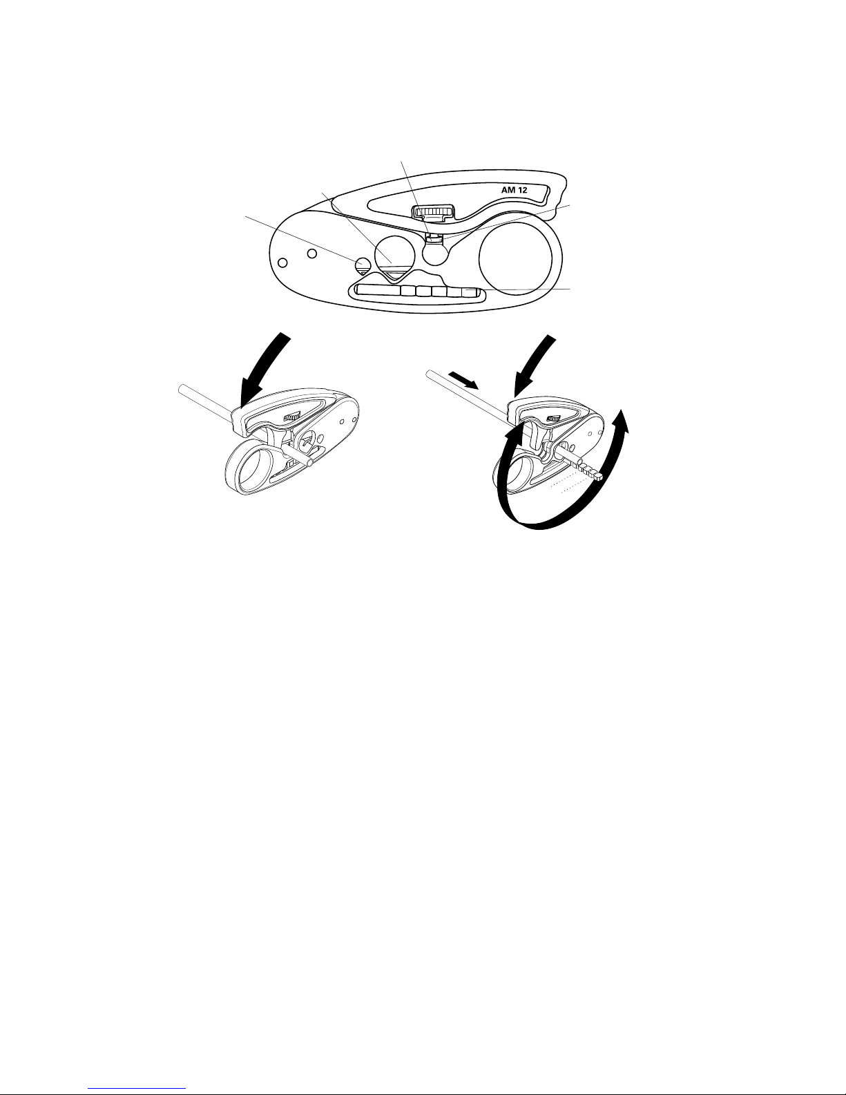
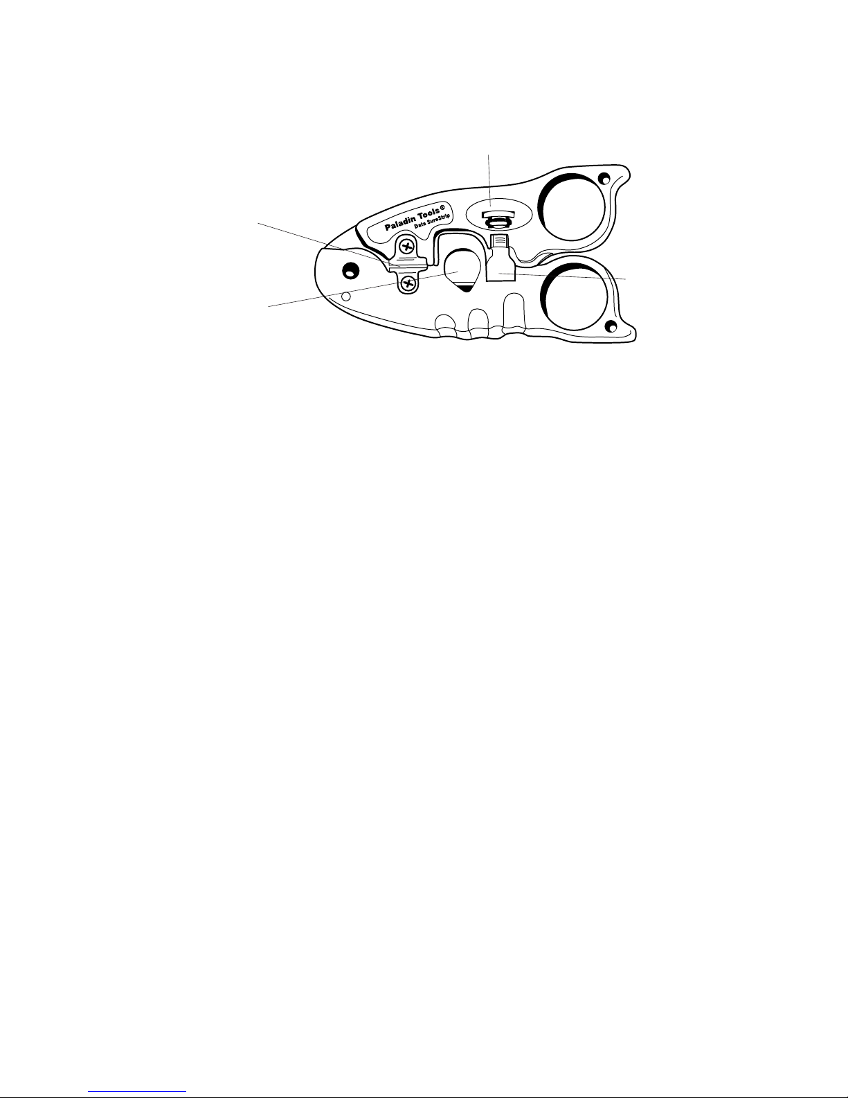
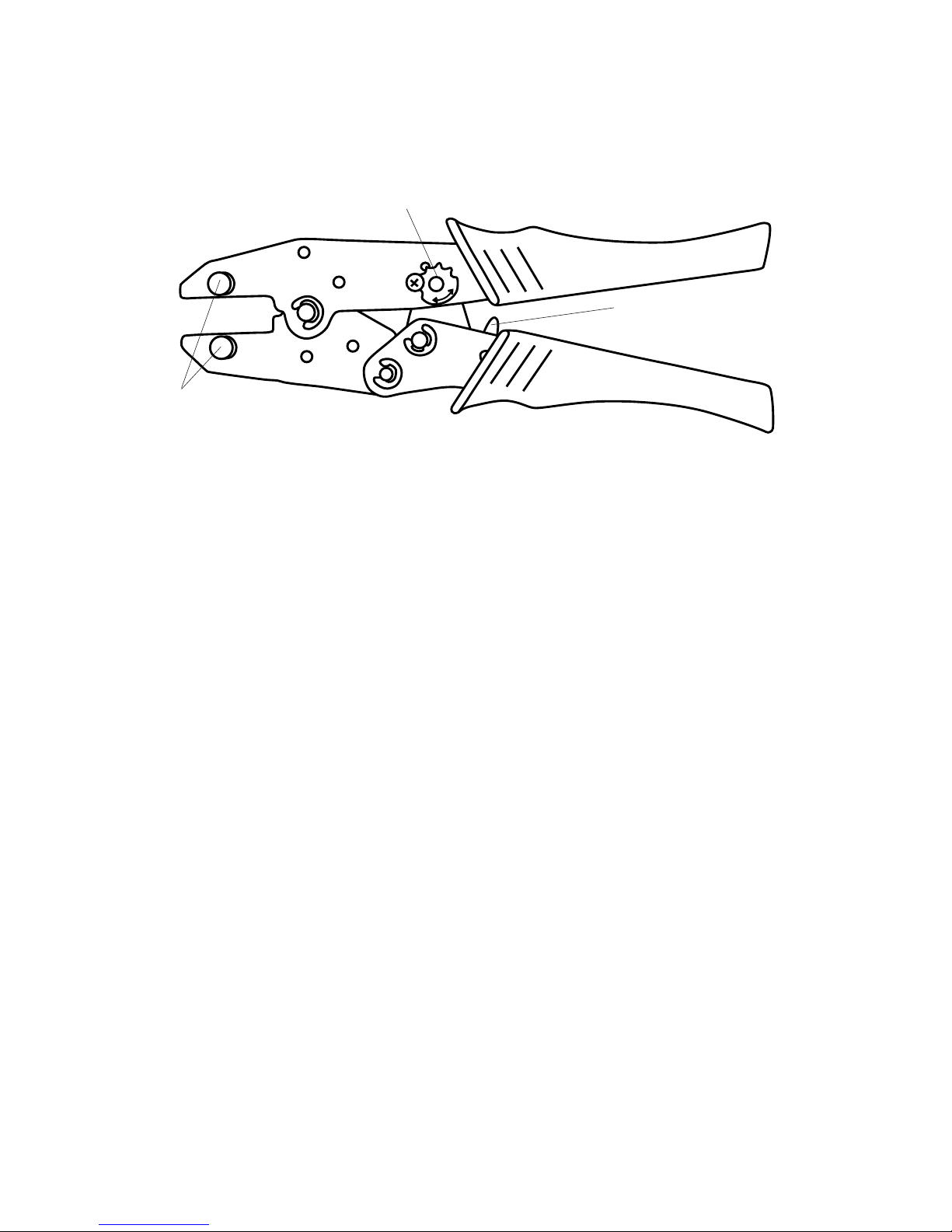
Blade Depth Adjustment Screw
Round Cable
Stripper
Cable
Cutter
1116Data SureStrip™ Twisted Pair
Cable Stripper
To cut wire & cable:
1. Install the wire or cable into the cable cutter section.
2. Grip the tool & squeeze the top handle down until
the article is cut.
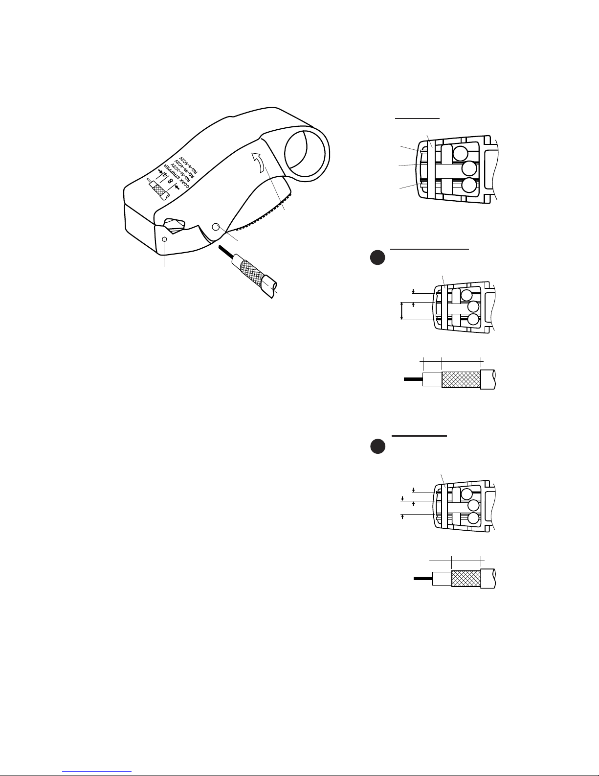
To strip round wire & cable:
1. Adjust the blade depth screw to set the blade cut
depth to desired level to ensure a non-scoring strip.
This may take several test settings before achieving
optimum depth.
2. Place wire/cable into the center round hole of the
tool.
3. Place your finger into the finger loop & spin the
tool clockwise around the cable 3 to 6 times. Do
not press down on the top lever. The tool has a
self-regulating spring to control stripping.
4. Open the tool & remove the cable. Pull the stripped
insulation off the cable.
To strip lat satin telephone cable:
1. Place cable into the flat cable stripper area located
at the front of the tool.
2. Close the tool & hold tool in palm or one hand, &
hold the cable steady in other hand.
3. Using a straight, no-angled motion, pull the tool
away & off from the end of the cable. This will strip
off the outer jacket exposing the inner conductors.
Perfect for 25-Pair!
Flat Cable
Stripper

Paladin Tools®3
1113 pictured
To cut wire:
1. Place the wire in the cutting slot located in the
bottom handle.
2. Squeeze the handles to close the cutting blade.
To strip wire:
1. Adjust the orange wire stop located in the jaws of
the tool to the desired strip length. Squeeze the
sides of the stop & slide to the proper length. Use
the metric ruler on the side of the tool as a guide
for the length.
2. Adjust the top slider for the proper insulation thick-
ness of the wire. Position the button fully forward
for thicker insulation & fully backward for thinner
insulation.
3. Insert the wire into the front of the jaws. Make
sure the end of the wire is flush against the front
edge of the wire stop.
4. Squeeze the handles to close the jaws & engage
the stripping blades.
Note: Not for use on Teflon or apton insulated wire
1113 & 1114 stripax® Pro Wire
Strippers
Wire stop
Cutting slot

Tool Operation and Use Guide
4
Paladin Tools®AM 25
1820
Paladin
Tools®
1822
1820 Series Cable Strippers/Slitters
Operating instructions:
1. Rotate the silver blade head in clockwise or counter-
clockwise directions to decrease or increase the
blade cutting depth respectively. (For 1822, rotate
bottom knob to set cable diameter)
2. Lift the spring-loaded retaining clamp & install the
cable. Release the clamp to allow the clamp to hold
the cable in place.
(cont’d on page 5)
Retaining
clamp
system
Spring-
loaded
blade
direction
trigger
Paladin Tools®AM 35
1821

Paladin Tools®5
3. For circular slitting, rotate the tool clockwise about
the cable until adequate penetration of the insula-
tion is achieved.
4. For longitudinal slitting, push & hold the trigger to
the right & slide the tool down the length of the
cable.
5. For spiral slitting, push & hold the trigger in the
center & rotate the tool down the length of the
cable. This creates a “corkscrew”-type slit. Remove
the tool from the cable.
6. After cable is slit, remove the insulation by pressing
the pointed end of the cable clamp into the groove
& pulling the insulation away. Peel off the remaining
loose insulation.
To replace blades:
1. Lift the cable clamp up.
2. Unscrew the silver head.
3. Remove spring, blade & washer.
4. Remove washer from “old” blade.
5. Spare blade is in handle. Remove cap from bottom
corner to access. (For 1822, spare blades on side
of handle)
6. Replace cap.
7. Slip washer over blade.
8. Install new blade/washer & then replace spring.
9. Screw silver head back on.

Tool Operation and Use Guide
6
1240 Series CST (Coax) Strippers
To strip coaxial cable:
1. Make sure the blade cassette is installed in the
back section of the tool.
2. Fully retract the rollers by moving the cam switch
lever to the full, back position.
3. Push the locking slide on the bottom to the fully
advanced position.
4. Insert the cable into the side of the tool where the
arrow indicates.
5. Push the cam switch lever to the fully forward
position to lock the cable in place. Pull the locking
slide on bottom of tool back to set the cam.
6. Adjust the screws located on the back side of the
tool to position the blade cutting depths for each
stripping level (jacket, shield, inner dielectric
insulation).
7. Place your finger in the round hole & rotate the
tool around the cable clockwise in the direction of
the arrow.
8. old the cable with one hand & pull the tool out
away from the cable to strip.
9. Repeat the above steps until the proper cutting
depth is achieved.
Cam
Y-block
Adjustment
screws
Memory
cassette

Paladin Tools®7
To strip coaxial cable:
1. Set up blade strip lengths to
Option “A” or “B” by removing the
retaining pin from the bottom jaw.
Move the blades to the desired strip
length channels. For 2-level strip,
remove center blade. Re-insert the
retaining pin.
2. Adjust blade depth using the hex
key to turn the hex screws in
bottom jaw for each blade.
3. Test strip. Install cable in front of
tool in direction of graphic. Rotate
tool clockwise 6 times around cable.
Remove tool from cable and remove
stripped layers with fingers.
4. Repeat set-up of strip length &/or
depth until desired strip is achieved.
Notes:
1. The 1257 is preset for standard RG6 CATV “F” cable.
See step 2 above to adjust blades for RG59 cable.
2. Do not hold jaws down during stripping; jaws adjust
automatically.
1255 LC CST-58/59
in
APre-set blade positions
a b d
.157 .315
.157” (4mm)
.315”
(8mm)
1255, 1256, 1257 & 1258 LC CST Coax
Strippers
Blade detail
1255 Example
Direction to rotate
around cable
Conductor blade
Conductor blade
Shaft pin
Retaining pin
for fixed blades
Shield/
braid blade
Retaining pin
BOptional user-set
blade positions
a b c
in
.157 .236
.157” (4mm)
.236”
(6mm)

Tool Operation and Use Guide
8
1300 Series Crimpers
Operating Instructions:
1. Install the required die set in the crimp tool by
removing the thumb screws located in the jaws.
Install the die set with the text facing outward
when crimper is in position shown above.
2. Install the thumb screws & tighten to maximum
thumb tightness. Note: Do not use pliers or tools
to tighten the thumb screws—only hand tighten-
ing is necessary.
3. Assemble cable & connector as specified by the
connector & cable manufacturers’ instructions.
4. Insert connector/cable assembly into the die set &
squeeze the handles through a complete ratchet
cycle. Crimp is complete.
Emergency release:
In the case of an emergency where a crimp cycle is
stopped & the tool needs to be reopened, flip the
safety release forward in the direction of the jaws to
engage the release mechanism.
Ratchet strength adjustment:
See page 11 for optimum ratchet gear settings &
adjustments.
Ratchet strength
adjustment
Safety release
Thumb screws

Paladin Tools®9
8000/CrimpALL® Series Crimpers
Safety release
Operating Instructions:
1. Install the required die set in the crimp tool by
removing the thumb screws located in the jaws.
Install the die set with the text facing outward
when crimper is in position shown above.
2. Install the thumb screws & tighten to maximum
thumb tightness. Note: Do not use pliers or tools
to tighten the thumb screws—only hand tighten-
ing is necessary.
3. Assemble cable & connector as specified by the
connector & cable manufacturers’ instructions.
4. Insert connector/cable assembly into the die set &
squeeze the handles through a complete ratchet
cycle. Crimp is complete.
Emergency release:
In the case of an emergency where a crimp cycle is
stopped & the tool needs to be reopened, flip the
safety release forward in the direction of the jaws to
engage the release mechanism.
Ratchet strength adjustment:
See page 11 for optimum ratchet gear settings &
adjustments.
Thumb screws
Ratchet strength
adjustment

Tool Operation and Use Guide
10
1600 Series Crimpers
To crimp a cable assembly:
1. For interchangeable-die crimp tools, install the
required die set in the crimp tool by removing the
screws located in the jaws. Install the die set in
the jaws & tighten the screws to securely hold the
die set.
2. Assemble cable & connector as specified by the
connector & cable manufacturers’ instructions.
3. Insert connector/cable assembly into the die set &
squeeze the handles through a complete ratchet
cycle. Crimp is complete.
Emergency release:
In the case of an emergency where a crimp cycle is
stopped & the tool needs to be reopened, flip the
safety release forward in the direction of the jaws to
engage the release mechanism. The release is located
between the handles.
Ratchet strength adjustment:
See page 11 for optimum ratchet gear settings &
adjustments.
Ratchet strength
adjustment
Safety release
Die screws

Paladin Tools®11
Ratchet Gear Settings
Recommended ratchet gear settings or optimum crimp per ormance:
1300 8000 1600
Cable Size/Type Series Series Series
Fiber optic: SMA, SC, ST, STII, FC connectors 2 2 2
Small coax: RG178, RG179, RG188, RG174, NT735, AT&T 735, mini-59 2 2 2
Coax: RG6, RG6 QS, Belden 1694, Belden 8281 (any 0 up to .310”) 3 3 3
Coax: RG8, RG11, RG212, RG213 4 4 N/A
4-pair data cables & flat satin for modular plugs 2 2 N/A
ook up wire for insulated & non-insulated terminals & splices 12-8 AWG 3 3 N/A
ook up wire for insulated & non-insulated terminals & splices 26-14 AWG 2 2 2
ook up wire for open barrel contacts & pins, 32-18 AWG 2 2 2
ook up wire for wire ferrules, 32-14 AWG 2 2 2
ook up wire for wire ferrules, 12-8 AWG 3 3 3
Setting the ratchet gear:
1. Remove the screw from the ratchet gear.
2. Rotate the gear until the required tooth slot is located over the slot hole.
3. Install & tighten the screw into the ratchet gear.
Note: Settings are averages & may vary according to actual cable & crimp article being used.

Tool Operation and Use Guide
12
1555 SealTite® Pro Universal Linear
Compression Crimper
1. Determine if the tool is set for the type of connector
you are crimping.
Head Connector Head
Side Types Position
CATV “F” CATV “F” Barrel end faces cable entry (Fig. 1)
Universal RCA, BNC & others Circular disk end faces cable entry (Fig. 2)
2. To properly attach the head, completely screw it on
until it stops & rests against the adjustment screw.
3. Rotate the lock nut counter-clockwise to unlock the
adjustment screw.
4. Refer to enclosed connector cross-reference &
setting matrix to determine the proper setting for
your connector.
(cont’d on page 13)
Figure 1
CATV “F” Head
osition
Figure 2
Universal Head
osition
Cable holding jaws
Adjustable head Adjustable screw
Locking unit
Ratchet
Ratchet release
Numbered setting
guide

Paladin Tools®13
5. Rotate the adjustment screw clockwise or counter-
clockwise to set the proper distance. Align the flat
edge of the disc to the number indicator positions
beneath the head. When desired setting is reached,
turn the lock nut clockwise to lock the adjustment
screw in place.
6. Strip the cable & assemble with connector according
to the connector manufacturer’s specifications. See
page. 24 or SealTite® CATV “F” instructions.
7. Insert the connector front end first to rest into the
head. Snap the cable into the cable entry holding
jaws. (Figure 3)
8. Squeeze the handles to close the tool through one
complete ratchet cycle until the tool automatically
opens.
9. Remove the crimped cable assembly.
1. Strip the cable & assemble with con-
nector according to the connector
manufacturers’ specification. See page
24 for SealTite CATV “F” instructions.
2. Install the connector assembly into
the tool with the head facing down-
ward & positioned over the center
crimp plate.
3. Insert the cable into the “grips” at the
top of the tool.
4. Close the handles through a complete
ratchet cycle to seal the connectors.
Crimp is complete.
Notes:
Terminates connectors with finished
crimp length of 19.5 - 21.5 mm only.
901024 SealTite® 59/6 Cable TV “F”
Compression Crimper
Safety
release
Grips

Tool Operation and Use Guide
14
1530R & 1540 All-in-One Pro Data/Phone
Tools
To cut & strip telephone cable:
1. To cut & strip 4- & 6-conductor flat cable, insert the cable
into the slot labeled 6 mm. Squeeze the handles to close
the blades & cut the cable.
2. Rest the cut cable end on the inside ridge for 6 mm.
Squeeze the handles to close the stripping blades & pull
the cable out to strip the outer insulation.
3. For 8-conductor cables, perform step 1 using the 12 mm
slot position.
To crimp cable:
1. Assemble cable according to the connector manufacturer’s
instructions & according to the required pin-out. See
pages 28 - 31 for reference.
2. Install the connector/cable assembly with the key tab
facing upward into the required 4-pin, 6-pin or 8-pin
crimp. Squeeze the handles through a complete ratchet
cycle. andles will reopen when crimp is complete.
Note: The 1530R is for WE/SS modular plugs; the 1540 is
for AMP (Tyco) plugs.
Connector Crimp Cavity
RJ22 handset 4P
RJ11/12 6P
RJ45 8P
Safety release

Paladin Tools®15
1556 & 1557 All-in-One Data/Phone Tools
To cut lat and round cable:
1. Open the tool completely by squeezing handles
together through a complete ratchet cycle.
2. Insert the cable to be cut into the cable cutter on
the back side of the tool.
3. Fully close the tool through a complete ratchet cycle
to cut the cable.
4. Ratchet the tool into the open position and remove
the cut cable.
RJ45 8 ole crimp
Flat cable cutter
& stripper

Tool Operation and Use Guide
16
To strip lat satin cable:
1. Open the tool completely by squeezing handles
together through a complete ratchet cycle.
2. For 6-conductor cable, insert it into the flat cable
cutter/stripper cavity and rest the front of the
cable on the small ridge located inside the handle
under the blades.
3. For 8-conductor cable, insert it into the same
cavity under the blades until the end protrudes
from the back side of the tool.
4. Close the handles and hold in place while pulling
the cable out. Cable is stripped to proper length.
To strip round UTP/STP cable:
1. Open the tool completely by squeezing handles
together through a complete ratchet cycle.
2. Insert the cable into the round cable stripping area.
3. Fully close the tool through one ratchet cycle and
hold closed.
4. Gently rotate the tool counter-clockwise around the
cable 3-6 times. Do NOT use the tool to pull the
outer jacket o cable.
5. Ratchet the tool to the open position.
6. Remove the cable from the tool and pull the outer
jacket off with your hand.
7. Verify inner wires were not scored. (If so, repeat
steps 1 - 6.)
To crimp modular plugs:
1. Assemble the cable according to the connector manu-
facturer’s instructions & according to the required
pin-out.
2. Open the tool completely by squeezing handles
together through a complete ratchet cycle.

Paladin Tools®17
3. Insert the connector/cable assembly with the key
tab facing downward into the required cavity
(see chart below)
Connector Crimp Cavity
Type Cavity Location
RJ45 8P Front of tool
RJ11 & RJ12 6P Front of tool
RJ22 handset 4P Back of tool
4. Close the handles through a complete ratchet
cycle until handles open. Crimp is complete.

Tool Operation and Use Guide
18
901014 & 901016 All-in-One Ultra
Data/Phone Tools
To cut & strip telephone cable:
1. To cut & strip 4- & 6-conductor flat cable, insert the cable
into the slot labeled 6 mm. Squeeze the handles to close
the blades & cut the cable.
2. Rest the cut cable end on the inside ridge for 6 mm.
Squeeze the handles to close the stripping blades & pull
the cable out to strip the outer insulation.
3. For 8-conductor cables, perform step 1 using the 12 mm
slot position.
To crimp cable:
1. Assemble cable according to the connector manufacturer’s
instructions & according to the required pin-out. See pages
28 - 31 for additional instructions.
2. Install the connector/cable assembly with the key tab
facing upward into the required 4-pin, 6-pin or 8-pin
crimp. Squeeze the handles through a complete ratchet
cycle. andles will reopen when crimp is complete.
Note: The 901016 is for WE/SS modular plugs; the 901014
is for AMP (Tyco) plugs.
Connector Crimp Cavity
RJ22 handset 4P
RJ11/12 6P
RJ11-DEC 6P (loosen screw on left-side of cavity & remove insert)
RJ45 8P
Safety release

Paladin Tools®19
3590 Series SurePunch® Pro
Punchdown Tool
Installing the blades:
1. Insert blade into the top of the tool.
2. Rotate the blade counterclockwise until it snaps (locks)
into place.
Attaching the light:
1. Ensure the lock clip on the light module is in the up
position.
2. Slide the light onto the mounting base located on the
bottom of the tool.
3. Press down on the lock clip to lock the light onto the
mount.
4. To remove light, push the lock clip in the up position.
5. Slide the light forward.
(cont’d on page 20)
Spudger
Hook
Slitting tooth/
pick
Table of contents
Other Paladin Tools Tools manuals
Popular Tools manuals by other brands

Nitto Kohki
Nitto Kohki A-300 instruction manual

Scheppach
Scheppach UMF1550 Translation from the original instruction manual

Beta
Beta 1461/C28B Instructions for use

Launch
Launch X-631 Maintenance manual

Atlas Copco
Atlas Copco EP5PTX15SR10-AT Safety information

Lincoln
Lincoln PowerLuber 1400 quick start guide