Palazzetti GLA810 User manual

GLASS GLA810
Installazione Termoregolatore
Thermoregolator Installation
Installation des Temperaturregler
Installation du Thermoregolateur
Instalación del Termorregulador

2 004725259 - 05/05/2022
Termoregolatore GLA810 Glass Manuale installazione
1. GENERALITÀ
Il Termoregolatore GLA810 è uno strumento per la gestione e controllo di Sufe
e Termocamini a Legna con riscaldamento ad Aria.
A1 2
Norme di Sicurezza
Leggere attentamente le note sulla sicurezza riportate di seguito, così da preve-
nire eventuali danni e pericoli alle persone e ai beni.
Prima di eseguire lavori sull‘impianto, attenersi
• alle norme antinfortunistiche,
• alle norme sulla protezione ambientale,
• alle norme dell‘Istituto Nazionale per l‘Assicurazione contro gli Infortuni sul
Lavoro,
• alle norme di sicurezza riconosciute
• Queste istruzioni per l‘uso si rivolgono esclusivamente al personale tecnico.
• I lavori elettrici devono essere eseguiti solo da tecnici qualificati in elettro-
tecnica.
• La prima messa in servizio dell‘impianto deve essere eseguita da personale
esperto o dal fabbricante o da un tecnico da lui nominato

004725259 - 05/05/2022 3
ITALIANO ENGLISH DEUTSCH FRANÇAIS ESPAÑOL
Dichiarazione di Conformità
Norme applicate:
EN 60730-1 50081-1
EN 60730-1 A1 50081-2
TiEmme elettronica
06055 Marsciano (PG) Italy
Tel.+39.075.874.3905; Fax. +39.075.874.2239
Dati Tecnici
Alimentazione: 230 Vac 50
Hz ± 10%
Assorbimento: 2 VA
Uscita Ventola: 250 Vac 0,8A/
Uscita Ventola: 250 Vac 1,5 A
Vers. potenziata
Uscita Relè: 250 Vac 3A
Fusibile Interno: T1,6 A
Sonde di lettura:
• NTC10K @25°C; -10 ÷ 110 °C
• NTC100K @25°C; -10 ÷300 °C
Caratteristiche
Meccaniche
Materiale: ABS Pla-
stica
Installazione: Incasso
3 Moduli
Dimensioni Incasso:
120x80x55 mm
Grado di Protezione:
IP40
Condizioni di
Installazione e Utilizzo
Temperatura di funzio-
namento:0÷40 °C
Temperatura di stoc-
caggio: 0÷60 °C
Umidità: 85% @25°C
2. INSTALLAZIONE
Prima di fare qualsiasi operazione, assicurarsi che la Tensione di Rete
sia disinserita
• Installare il prodotto solo in ambienti asciutti e in condizioni climatiche corrette
• Inserire a nonte dell’impianto un interruttore bipolare conforme alle norme vi-
genti
• Evitare di accoppiare i cavi delle sonde con quelli di potenza
• Utilizzare per i collegamenti elettrici cavi con conduttori di sezione opportuna
e a norma
• Posizionare le sonde in modo da rilevare correttamente le temperature
• Accertarsi che i cavi sonda non siano a contatto diretto/indiretto con la fiamma

4 004725259 - 05/05/2022
3. COLLEGAMENTI ELETTRICI
F USE
T1, 6A 12 11 10 9
S1S2
1567
234
LI N EA
230Vac
L-ON
L
N
8
N
VENT
230Vac
SERVIN
SCI
Tutte le Uscite di comando e gli Ingressi sonde
sono controllati automaticamente in base alla
tipologia/schema di Impianto prescelto.
Pertanto per i collegamenti elettrici
è NECESSARIO fare riferimento al capitolo 8 e
successivi paragrafi degli Schemi Impianto.
Fig.2 – Collegamenti elettrici
Sigla Morsetti Dispositivo Caratteristiche
INGRESSI
LINEA 1 2 Alimentazione di
Rete 230 Vac 50 Hz ± 10%
IN SCI 3 4 Consenso Scintilla Ingresso 230 Vac 50 Hz ± 10%
S1 9 10 Sonda Tempera-
tura Aria/ Termo-
stato Ambiente
Range di funzionamento: -10°C
÷ 180 °C
NTC 100K Misura: -10 ÷ 300 °C
± 1°C
S2 11 12
Sonda Tempera-
tura Ambiente /
Termostato Am-
biente
Range di funzionamento: -10°C
÷ 125 °C
NTC 10K Misura: -10 ÷ 110 °C ±
1°C
USCITE
VENT 5 6 Ventilatore 230 Vac 0,8A
SERV 7 8 Uscita Servizio Contatti liberi: COM. (7) - N.O.
(8)

004725259 - 05/05/2022 5
ITALIANO ENGLISH DEUTSCH FRANÇAIS ESPAÑOL
Solo in caso di “Kit ventilazione frontale” è necessario modificare il cablaggio
come di seguito:
1
3 4
2
1
2 4
3

6 004725259 - 05/05/2022
4. FUNZIONALITÀ
4.1 USCITA SERVIZIO
L’Uscita SERVIZIO è programmabile da MENU Installatore dal parametro P02:
• P02 = 0 DISABILITATA: l’uscita non funziona
• P02 = 1 TERMOSTATO: l’uscita è attiva se la temperatura della Sonda S1 è
maggiore del Termostato E07
• P02 = 2 GRILL: premendo per 3 secondi il pulsante K3 si può accendere/
spegnere l’uscita
• P02 = 3 SERRANDA ARIA: l’uscita gestisce una serranda per la regolazione
dell’aria comburente
• P02 = 4 SCINTILLA: l’uscita gestisce il comando scintilla
Le funzioni TERMOSTATO e SERRANDA ARIA sono disabilitate nel caso di
P17=1.
4.2 CONFIGURAZIONE INGRESSO S2
Tramite il parametro P01 è possibile abilitare le seguenti gestioni:
• P01 = 0, ingresso S2 = DISABILITATO
• P01 = 1, ingresso S2 = SONDA AMBIENTE
• P01 = 2, ingresso S2 = TERMOSTATO AMBIENTE
4.3 FUNZIONE DI SPUNTO VENTOLA
Questo funzionamento ci permette di mandare il Ventilatore alla Velocità Mas-
sima, per un tempo programmabile (t08), ogni volta che deve partire da fermo.
Scaduto il tempo il Ventilatore prenderà la velocità programmata.
Per disabilitare la Funzione di Spunto, programmare il tempo t08 a 0 secondi.

004725259 - 05/05/2022 7
ITALIANO ENGLISH DEUTSCH FRANÇAIS ESPAÑOL
5. MENU’
5.1 MENU’ INSTALLATORE
L’accesso a tale Menu è di COMPETENZA di INSTALLATORI o DI PERSONALE
ESPERTO, in quanto i parametri riportati se modificati possono rendere il pro-
dotto non adatto alla applicazione in uso.
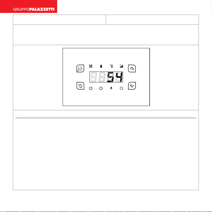
• Per accedere al MENU premere contemporaneamente i tasti K2 e K4 per
circa 3 secondi.
• Per scorrere i codici dei parametri utilizzare i tasti K3 e K4
• Per visualizzare il valore del parametro ed entrare in modifica premere il
tasto K2
• Per modificare il valore premere i tasti K3 e K4
• Per salvare il nuovo valore pigiare il tasto K2.
• Per uscire senza salvare pigiare il tasto K1
• Pigiare nuovamente il tasto K1 per uscire dal Menù o attendere 60 secondi
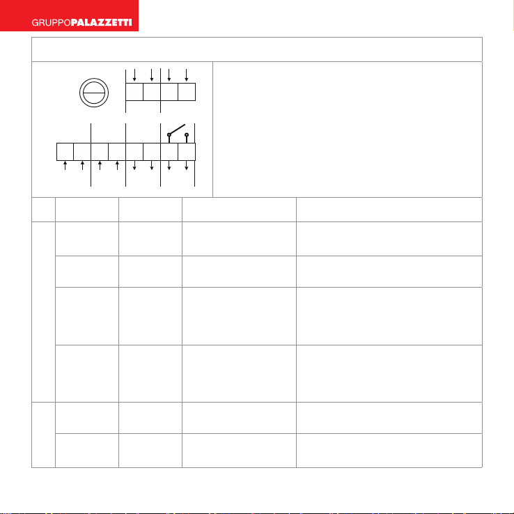
Descrizione Cod. Min Set Max U.M.
Termostato Aria per Attivazione Ventola E01 30 45 100 [°C]
Termostato Aria per SICUREZZA E02 80 100 140 [°C]
Termostato Aria per ALLARME E03 100 120 180 [°C]
Termostato Aria per SICUREZZA VENTI-
LATORE E04 100 135 180 [°C]
Termostato Aria per Apertura Valvola E05 20 30 140 [°C]
Termostato Aria per Chiusura Valvola E06 20 80 140 [°C]
Termostato Aria per Attivazione uscita
SERVIZIO E07 20 50 180 [°C]
Delta di Temperatura per funziona-
mento Proporzionale E50 20 20 100 [°C]

8 004725259 - 05/05/2022
Isteresi termostato Attivazione Ventola IE01 1240 [°C]
Isteresi termostato per SICUREZZA IE02 1240 [°C]
Isteresi termostato per ALLARME IE03 1240 [°C]
Isteresi termostato per SICUREZZA
VENTILATORE IE04 1 240 [°C]
Isteresi termostato per Apertura Valvo-
la IE05 1 240 [°C]
Isteresi termostato per Chiusura Valvo-
la IE06 1 240 [°C]
Isteresi termostato per Attivazione
uscita SERVIZIO IE07 1240 [°C]
Isteresi termostato Ambiente Ib01 0 120 [°C]
Velocità P01 Ventola (minima) UA01 20 1100 [%]
Velocità P09 Ventola (nona) UA09 80 1100 [%]
Velocità P10 Ventola (massima) UA10 100 1100 [%]
Tempo di Ritardo Chiusura Serranda
Aria t 06 010 120 [min]
Tempo di sospensione allarme Acusti-
co t 07 1560 [min]
Tempo di Spunto Ventilatore t 08 0210 [sec]
Configurazione Ingresso S2; 0= Non
usato; 1 = Sonda; 2 = Termostato P01 002 n
Configurazione Uscita SERVIZIO P02 003 n

004725259 - 05/05/2022 9
ITALIANO ENGLISH DEUTSCH FRANÇAIS ESPAÑOL
Abilitazione SICUREZZA VENTILATORE P03 011 n
Abilitazione SICUREZZA Aria P04 011 n
Abilitazione ALLARME Aria P05 011 n
Abilitazione Funzione Start Serranda
Aria P12 001 n
Configurazione Ingresso S1; 1 = Sonda;
2= termostato P17 112 n
NOTE: modificando UA01, UA09, UA10, il Ventilatore prende subito la velocità
che si stà tarando in modo da vederne l’effetto.

10 004723012 - 05/05/2022
Temperature control unit GLA810 Glass Instruction Manual
1. GENERAL INFORMATION
The GLA810 Temperature control unit is an instrument for the management
and control of Wood-burning Stoves and Fireplaces with Air heating.
A1 2
Safety Standards
Carefully read the following safety notes, so as to prevent any damage and dan-
ger to people and things.
Before performing any work on the system, follow
• the accident prevention rules,
• the environmental protection rules,
• the norms of the Istituto Nazionale per l’Assicurazione contro gli Infortuni
sul Lavoro (National Institute for Insurance against Accidents at Work),
• accepted safety rules.
• These instructions for use are addressed exclusively to the technical personnel.
• Electrical work must be performed only by qualified electrical engineering
technicians.
• The initial commissioning of the installation must be performed by skilled
personnel or by the manufacturer or by a tec

004723012 - 05/05/2022 11
ITALIANO ENGLISH DEUTSCH FRANÇAIS ESPAÑOL
Conformity Declaration
Applied standards:
EN 60730-1 50081-1
EN 60730-1 A1 50081-2
TiEmme elettronica
06055 Marsciano (PG) Italy
Tel.+39.075.874.3905; Fax. +39.075.874.2239
Technical Specifications
Power supply: 230 VAC 50 Hz
± 10%
Absorption: 2 VA
Fan Output: 250 VAC 0.8A/
Fan Output: 250 VAC 1.5A Vers.
boosted
Relay Output: 250 VAC 3A
Internal Fuse: T1.6 A
Reading probes:
• NTC10K @25°C; -10 ÷ 110 °C
• NTC100K @25°C; -10 ÷300 °C
Mechanical
Characteristics
Material: ABS Plastic
Installation: Built in 3
Modules
Built in size:
120x80x55 mm
Degree of Protection:
IP40
Condizioni di
Installazione e Utilizzo
Conditions of Installa-
tion and Operation
Operating temperatu-
re: 0 ÷ 40° C
Storage temperature: 0
÷ 60 °C
Humidity: 85% @25°C
2. INSTALLATION
Before carrying out any operation, make sure that the mains voltage
is switched off
• Install the product only in dry environments and in correct climatic conditions
• At the head of the installation, insert a bipolar switch in compliance with cur-
rent regulations
• Avoid coupling the probe cables with power circuit cables
• Use electrical connection cables with conductors of appropriate section and
in compliance
• Place the probes in such a way as to correctly detect the temperatures
• Make sure that the probe cables are not in direct/indirect contact with the fla-
me

12 004723012 - 05/05/2022
3. ELECTRICAL CONNECTIONS
F USE
T1, 6A 12 11 10 9
S1S2
1567
234
LI N EA
230Vac
L-ON
L
N
8
N
VENT
230Vac
SERVIN
SCI
All the control Outputs and probe Inputs are
controlled automatically according to the
type/diagram of the chosen Installation.
Therefore, for the electrical connections
you MUST refer to chapter 8 and the subse-
quent paragraphs of the Installation Diagrams.
Fig. 2 - Electric connections
Initials Terminals Device Charateristics
INPUTS
LINE 1 2 Mains Power Sup-
ply 230 Vac 50 Hz ± 10%
IN SCI 3 4 Spark Consent Input 230 Vac 50 Hz ± 10%
S1 9 10
Room Temperatu-
re Probe /
Room Temp. Ther-
mostat
Range of operation: -10°C ÷ 180
°C
NTC 100K Misura: -10 ÷ 300 °C
± 1°C
S2 11 12
Room Temperatu-
re Probe /
Room Temp. Ther-
mostat
Range of operation: -10°C ÷ 125
°C
NTC 10K Misura: -10 ÷ 110 °C ±
1°C
OUTPUTS
VENT 5 6 Fan 230 Vac 0,8A
SERV 7 8 Service Output Free contacts: COM. (7) - N.O.
(8)

004723012 - 05/05/2022 13
ITALIANO ENGLISH DEUTSCH FRANÇAIS ESPAÑOL
Only in case of “Front ventilation kit” it is necessary to modify the wiring as
follows:
1
3 4
2
1
2 4
3

14 004723012 - 05/05/2022
4. FUNCTIONS
4.1 SERVICE OUTPUT
The SERVICE Output is programmable from the Installer MENU of parameter
P02:
• P02 = 0 DISABLED: the output does not work
• P02 = 1 THERMOSTAT: the output is active if the temperature of the S1 Pro-
be is greater than the E07 thermostat
• P02 = 2 GRILL: pressing the K3 button for 3 seconds you can turn on or turn
off the output
• P02 = 3 DAMPER: the output manages a damper for the adjustment of the
combustion air
• P02 = 4 SPARK: the output manages the spark control
The functions THERMOSTAT AND DAMPER are disabled in the case of P17 = 1.
4.2 INPUT S2 CONFIGURATION
Using parameter P01 you can enable the following connection managers:
• P01 = 0, input S2 = DISABLED
• P01 = 1, input S2 = ROOM TEMP PROBE
• P01 = 2, input S2 = ROOM TEMP THERMOSTAT
4.3 FAN STARTING FUNCTION
This operation allows the Fan to operate at Maximum Speed for a program-
mable time (t08), every time that it has to start from a standstill. After the time
has lapsed the Fan will resume to programmed speed.
To disable the Fan Starting function, programme the time t08 to 0 seconds.

004723012 - 05/05/2022 15
ITALIANO ENGLISH DEUTSCH FRANÇAIS ESPAÑOL
5. MENU
5.1 INSTALLER MENU
Access to this Menu is the RESPONSIBILITY of INSTALLATION TECHNICIANS or
EXPERT PERSONNEL, because the parameters shown, if modified, may render
the product is not suitable for the application in use.
• To access the MENU simultaneously press the keys K2 and K4 for about 3
seconds.
• To scroll through the parameters, use the keys K3 and K4
• To view the value of the parameter and enter for modification, press the key K2
• To change the value, press the keys K3 and K4
• To save the new value, press the key K2.
• To exit without saving, press the key K1
Press the K1 key again to exit from the Menu or wait 60 seconds
Descrizione Cod. Min Set Max U.O.M.
Fan Activation Air Thermostat E01 30 45 100 [°C]
SAFETY Air Thermostat E02 80 100 140 [°C]
ALARM Air Thermostat E03 100 120 180 [°C]
FAN SAFETY Air Thermostat E04 100 135 180 [°C]
Valve Opening Air Thermostat E05 20 30 140 [°C]
Valve Closing Air Thermostat E06 20 80 140 [°C]
SERVICE output Fan Activation Air
Thermostat E07 20 50 180 [°C]
Temperature Range for Proportional
operation E50 20 20 100 [°C]
Fan Activation hysteresis thermostat IE01 1240 [°C]
SAFETY hysteresis thermostat IE02 1240 [°C]

16 004723012 - 05/05/2022
ALARM hysteresis thermostat IE03 1240 [°C]
FAN SAFETY hysteresis thermostat IE04 1 240 [°C]
Opening Valve hysteresis thermostat IE05 1 240 [°C]
Closing Valve hysteresis thermostat IE06 1 240 [°C]
SERVICE output Activation hysteresis
thermostat IE07 1240 [°C]
Room temperature hysteresis thermo-
stat Ib01 0 120 [°C]
Fan Speed P01 (minimum) UA01 20 1100 [%]
Fan Speed P09 (ninth) UA09 80 1100 [%]
Fan Speed P10 (maximum) UA10 100 1100 [%]
Delay Time Damper Closing t 06 010 120 [min]
Time of suspension of Acoustic alarm t 07 1560 [min]
Time of Fan Starting t 08 0210 [sec]
Input Configuration S2; 0 = not used; 1
= Probe; 2 = Thermostat P01 002 n
SERVICE Output Configuration P02 003 n
Enabling FAN SAFETY P03 011 n
Enabling Air SAFETY P04 011 n
Enabling Air ALARM P05 011 n
Enabling Damper Start Function P12 001 n
Input Configuration S2; 1 = Probe; 2 =
Thermostat P17 112 n
NOTES: Modifying UA01, UA09, UA10, the Fan immediately goes to the speed
that you are calibrating in order to see the effect.

004725259 - 05/05/2022 17
ITALIANO ENGLISH DEUTSCH FRANÇAIS ESPAÑOL
TemperaturreglerGLA810 Glass Bedienungsanleitung
1. ALLGEMEINES
Der Temperaturregler GLA810 ist ein Instrument zur Steuerung und Kontrolle
von Öfen und Thermokaminen für die Verfeuerung von Holz mit Luftheizung.
A
1 2
Sicherheitsnormen
Lesen Sie die nachfolgend angeführten Sicherheitsanweisungen aufmerksam
durch, um eventuellen Schäden an oder Gefahren von Personen und Gegen-
ständen vorzubeugen.
Halten Sie sich vor der Durchführung von Arbeiten an der Anlage an die
• Unfallverhütungsmaßnahmen,
• Umweltschutzmaßnahmen,
• Normen des Istituto Nazionale per l‘Assicurazione contro gli Infortuni sul
Lavoro (kurz: INAIL, deutsch: gesamtstaatliches Versicherungsinstitut für
Arbeitsunfälle) und an die
• anerkannten Sicherheitsnormen.
• Diese Verwendungshinweise richten sich ausschließlich an Fachpersonal.
• Die elektrischen Arbeiten dürfen nur von im Bereich Elektrotechnik qualifi-
ziertem Fachpersonal durchgeführt werden.
• Die erste Inbetriebnahme der Anlage muss von Experten oder vom Perso-
nal des Herstellers oder von einem vom Hersteller beauftragten Techniker
durchgeführt werden.

18 004725259 - 05/05/2022
Konformitätserklärung
Angewandte Normen:
EN 60730-1 50081-1
EN 60730-1 A1 50081-2
TiEmme elettronica
06055 Marsciano (PG) Italy
Tel.+39.075.874.3905; Fax.
+39.075.874.2239
Technische Daten
Stromversorgung: 230 V AC 50
Hz ± 10%
Absoprtion: 2 VA
Ausgang Ventil: 250 V AC 0,8A/
Ausgang Ventil: 250 V AC 1,5 A
verstärkte Version
Ausgang Relais: 250 V AC 3A
Innere Sicherung: T 1,6 A
Ablesesonden:
• NTC10K @25°C; -10 ÷ 110 °C
• NTC100K @25°C; -10 ÷300 °C
Mechanische Eigen-
schaften
Material: ABS-Kunst-
stoff
Installation: Einbau, 3
Module
Abmessungen des
Einbaus: 120x80x55
mm
Schutzgrad: IP40
Installations- und
Verwendungsbedin-
gungen
Funktionstemperatur:
0÷40 °C
Lagerungstemperatur:
0÷60 °C
Feuchtigkeit: 85%
@25°C
2. INSTALLATION
Stellen Sie vor dem Ausführen jeglicher Tätigkeiten sicher, dass die
Netzspannung unterbrochen ist.
• Das Produkt darf nur in trockenen Umgebungen und bei richtigen Klimabe-
dingungen installiert werden
• Vor der Anlage einen Wechselschalter, der den gültigen Normen entspricht, einfügen
• Die Verbindung der Kabel der Sonden mit jenen der Stromversorgung ist zu
vermeiden
• Verwenden Sie für die elektrischen Verbindungen der Norm entsprechende
Kabel mit geeignetem Querschnitt
• Die Sonden sind so zu positionieren, dass die Temperaturen richtig gemessen
werden können
• Stellen Sie sicher, dass die Kabel der Sonden nicht in direktem/indirektem Kon-
takt mit der Flamme stehen

004725259 - 05/05/2022 19
ITALIANO ENGLISH DEUTSCH FRANÇAIS ESPAÑOL
3. ELEKTRISCHE VERBINDUNGEN
F USE
T1, 6A 12 11 10 9
S1S2
1567
234
LI N EA
230Vac
L-ON
L
N
8
N
VENT
230Vac
SERVIN
SCI
Alle Steuerungsausgänge und Son-
deneingänge werden je nach vorab
gewählter Art / vorab gewähltem Sche-
ma der Anlage automatisch kontrolliert.
Aus diesem Grund ist es für elektrische
Verbindungen
NOTWENDIG, sich auf das Kapitel 8 und
die nachfolgenden Absätze der Anla-
genschemata zu beziehen.
Abb. 2 - Elektrische Verbindungen
Abkürzungen Klemmen Gerät Eigenschaften
EINGÄNGE
LINIE 1 2 Netzversorgung 230 V AC 50 Hz ± 10%
IN SCI 3 4 Zustimmung
Funken Eingang 230 V AC 50 Hz ±
10%
S1 9 10
Raumtempera-
tursonde /
Raumthermo-
stat
Funktionsbereich: -10°C ÷
180 °C
NTC 100K Messung: -10 ÷
300 °C ± 1°C
S2 11 12
Raumtempera-
tursonde /
Raumthermo-
stat
Funktionsbereich: -10°C ÷
125 °C
NTC 10K Messung: -10 ÷ 110
°C ± 1°C
AUSGÄNGE
VENT 5 6 Ventilator 230 V AC 0,8A
SERV 7 8 Serviceausgang Freie Kontakte: COM. (7) -
N.O. (8)

20 004725259 - 05/05/2022
Nur im Falle des „Belüftungskit vorne“ ist es notwendig, die Verkabelung wie
folgt zu ändern:
1
3 4
2
1
2 4
3
Other manuals for GLA810
1
Table of contents
Languages:
Other Palazzetti Industrial Equipment manuals