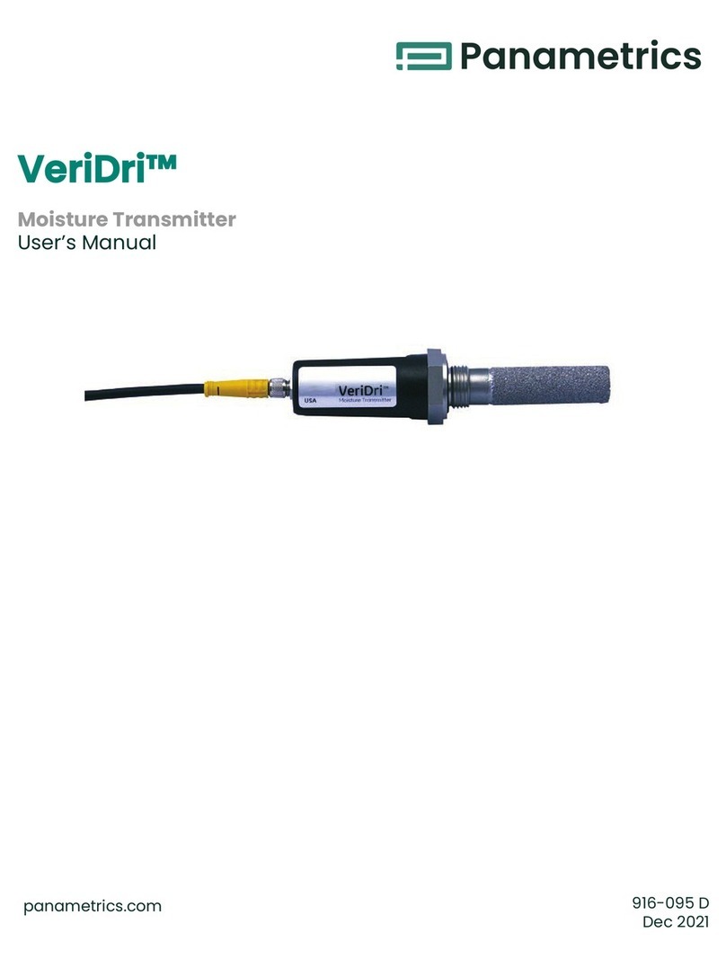
Panametrics DewPro MMR101 User manual


Moisture
panametrics.com
Copyright 2020 Baker Hughes company.
This material contains one or more registered trademarks of Baker Hughes Company and its subsidiaries
in one or more countries. All third-party product and company names are trademarks of their respective
holders.
DewProMMR101
High-Temperature Moisture Transmitter
User’s Manual
A40251516 Rev.B

ii
[no content intended for this page]

DewPro MMR101 User’s Manual v
Contents
Chapter 1. General Information
1.1 Introduction . . . . . . . . . . . . . . . . . . . . . . . . . . . . . . . . . . . . . . . . . . . . . . . . . . . . . . . . . . . . . . . . . . . . . . . . . . . . . . . . . . . . . . . . . . . . . . . . . . . . . .1
1.2 Unpacking. . . . . . . . . . . . . . . . . . . . . . . . . . . . . . . . . . . . . . . . . . . . . . . . . . . . . . . . . . . . . . . . . . . . . . . . . . . . . . . . . . . . . . . . . . . . . . . . . . . . . . . .1
1.3 Safety Notes . . . . . . . . . . . . . . . . . . . . . . . . . . . . . . . . . . . . . . . . . . . . . . . . . . . . . . . . . . . . . . . . . . . . . . . . . . . . . . . . . . . . . . . . . . . . . . . . . . . . . .1
1.4 Order Code . . . . . . . . . . . . . . . . . . . . . . . . . . . . . . . . . . . . . . . . . . . . . . . . . . . . . . . . . . . . . . . . . . . . . . . . . . . . . . . . . . . . . . . . . . . . . . . . . . . . . . 2
1.5 Instrument Components . . . . . . . . . . . . . . . . . . . . . . . . . . . . . . . . . . . . . . . . . . . . . . . . . . . . . . . . . . . . . . . . . . . . . . . . . . . . . . . . . . . . . . . . 3
1.6 Mode of Operation . . . . . . . . . . . . . . . . . . . . . . . . . . . . . . . . . . . . . . . . . . . . . . . . . . . . . . . . . . . . . . . . . . . . . . . . . . . . . . . . . . . . . . . . . . . . . . 4
Chapter 2. Installing the DewPro MMR101
2.1 Introduction . . . . . . . . . . . . . . . . . . . . . . . . . . . . . . . . . . . . . . . . . . . . . . . . . . . . . . . . . . . . . . . . . . . . . . . . . . . . . . . . . . . . . . . . . . . . . . . . . . . . . 5
2.2 Manually Setting the Measurement Units. . . . . . . . . . . . . . . . . . . . . . . . . . . . . . . . . . . . . . . . . . . . . . . . . . . . . . . . . . . . . . . . . . . . . . . . 5
2.3 Choosing a Mounting Location . . . . . . . . . . . . . . . . . . . . . . . . . . . . . . . . . . . . . . . . . . . . . . . . . . . . . . . . . . . . . . . . . . . . . . . . . . . . . . . . . . 7
2.3.1 Mounting the Unit . . . . . . . . . . . . . . . . . . . . . . . . . . . . . . . . . . . . . . . . . . . . . . . . . . . . . . . . . . . . . . . . . . . . . . . . . . . . . . . . . . . . . . . . . . . 8
2.3.2 Using a Compression Fitting. . . . . . . . . . . . . . . . . . . . . . . . . . . . . . . . . . . . . . . . . . . . . . . . . . . . . . . . . . . . . . . . . . . . . . . . . . . . . . . . 8
2.3.3 Using a Bracket. . . . . . . . . . . . . . . . . . . . . . . . . . . . . . . . . . . . . . . . . . . . . . . . . . . . . . . . . . . . . . . . . . . . . . . . . . . . . . . . . . . . . . . . . . . . . 9
2.3.4 Making Electrical Connections . . . . . . . . . . . . . . . . . . . . . . . . . . . . . . . . . . . . . . . . . . . . . . . . . . . . . . . . . . . . . . . . . . . . . . . . . . . . . 9
2.3.5 Preparation. . . . . . . . . . . . . . . . . . . . . . . . . . . . . . . . . . . . . . . . . . . . . . . . . . . . . . . . . . . . . . . . . . . . . . . . . . . . . . . . . . . . . . . . . . . . . . . . 10
2.3.6 System Configuration with One or Two 24 VDC Power Supplies . . . . . . . . . . . . . . . . . . . . . . . . . . . . . . . . . . . . . . . . . . . . 11
2.3.7 System Configuration with One 24 VDC Power Supply and Loop Powered Display. . . . . . . . . . . . . . . . . . . . . . . . . .12
2.3.8 System Configuration with External Power Supply and Display . . . . . . . . . . . . . . . . . . . . . . . . . . . . . . . . . . . . . . . . . . . . .13
Chapter 3. Operating the MMR101
3.1 Introduction . . . . . . . . . . . . . . . . . . . . . . . . . . . . . . . . . . . . . . . . . . . . . . . . . . . . . . . . . . . . . . . . . . . . . . . . . . . . . . . . . . . . . . . . . . . . . . . . . . . . 15
3.2 Powering Up . . . . . . . . . . . . . . . . . . . . . . . . . . . . . . . . . . . . . . . . . . . . . . . . . . . . . . . . . . . . . . . . . . . . . . . . . . . . . . . . . . . . . . . . . . . . . . . . . . . . 15
3.3 Displaying Measurements . . . . . . . . . . . . . . . . . . . . . . . . . . . . . . . . . . . . . . . . . . . . . . . . . . . . . . . . . . . . . . . . . . . . . . . . . . . . . . . . . . . . . . 15
3.4 Description of Matrix Options . . . . . . . . . . . . . . . . . . . . . . . . . . . . . . . . . . . . . . . . . . . . . . . . . . . . . . . . . . . . . . . . . . . . . . . . . . . . . . . . . . . .17
3.4.1 System Administration Options . . . . . . . . . . . . . . . . . . . . . . . . . . . . . . . . . . . . . . . . . . . . . . . . . . . . . . . . . . . . . . . . . . . . . . . . . . . . .17
3.4.2 Moisture Measurement Options . . . . . . . . . . . . . . . . . . . . . . . . . . . . . . . . . . . . . . . . . . . . . . . . . . . . . . . . . . . . . . . . . . . . . . . . . . . .17
3.4.2.1 Temperature Measurement Options . . . . . . . . . . . . . . . . . . . . . . . . . . . . . . . . . . . . . . . . . . . . . . . . . . . . . . . . . . . . . . . 20
3.4.3 Error Codes and Messages . . . . . . . . . . . . . . . . . . . . . . . . . . . . . . . . . . . . . . . . . . . . . . . . . . . . . . . . . . . . . . . . . . . . . . . . . . . . . . . .21
3.4.4 Measurement Accuracy. . . . . . . . . . . . . . . . . . . . . . . . . . . . . . . . . . . . . . . . . . . . . . . . . . . . . . . . . . . . . . . . . . . . . . . . . . . . . . . . . . . .21
Chapter 4. Troubleshooting
Chapter 5. Maintenance
5.1 Cleaning. . . . . . . . . . . . . . . . . . . . . . . . . . . . . . . . . . . . . . . . . . . . . . . . . . . . . . . . . . . . . . . . . . . . . . . . . . . . . . . . . . . . . . . . . . . . . . . . . . . . . . . . 25
5.2 Calibration . . . . . . . . . . . . . . . . . . . . . . . . . . . . . . . . . . . . . . . . . . . . . . . . . . . . . . . . . . . . . . . . . . . . . . . . . . . . . . . . . . . . . . . . . . . . . . . . . . . . . 25
5.3 Repairs . . . . . . . . . . . . . . . . . . . . . . . . . . . . . . . . . . . . . . . . . . . . . . . . . . . . . . . . . . . . . . . . . . . . . . . . . . . . . . . . . . . . . . . . . . . . . . . . . . . . . . . . . 25
Chapter 6. Specifications
Contents
vi DewPro MMR101 User’s Manual

DewPro MMR101 User’s Manual 1
Chapter 1. General Information
1.1 Introduction
The DewPro MMR101 is a moisture and temperature transmitter featuring two patented isolated 4 to 20-mA current
loops. The measuring range lies between 0 to 100% relative humidity at temperatures of up to 150oC (300oF). This
transmitter has been designed for use in low and high-temperature ranges, such as chemical processes, textile
production and the glass, cement and steel industries. This instrument can be used in pressurized and not
pressurized systems with pressures of up to 10 bar.
1.2 Unpacking
Inspect for any damaged packaging and contents. The post office or freight carrier must be informed of any
damage. Damaged merchandise must be retained until the matter has been settled.
Check that the delivery is complete and agrees with the shipping documents of your order (refer to nameplate for
type and variant).
The delivery comprises:
• DewProMMR101
• User’s Manual
• Depending on your order: process connection and display
• Calibration certificate
If you have any questions, consult your supplier or the Panametrics sales agency in your area (see back cover of
these operating instructions for addresses).
1.3 Safety Notes
• You should strictly adhere to the notes and warnings in this manual.
• Operating this instrument in any way other than as described in this manual may compromise the safety and
function of the measuring instrument.
• Troubleshooting should only be performed by authorized and trained personnel.
• To prevent accidental startup, remove the unit from service if you cannot remedy faults.
• Damaged equipment should be clearly identified as such to prevent danger.
• Repair work must be performed by authorized Panametrics Service Personnel.

Chapter 1. General Information
2DewPro MMR101 User’s Manual
1.4 Order Code
You can identify the various options for your unit by order code on the nameplate of the instrument.
Figure 1: Nameplate
Moisture Sensor DewPro MMR101
Certification/Approvals
R Standard (not certified)
A FM IS Class I, II, III; Division 1, Groups A-G, T4
B FM XP-IS Class I, Division 1, Groups A-D, T5
C FM NI Class, Division 2, Groups A-D, T4;
DIP Class II, III; Division 1, Groups E-G, T4
F ATEX II 3G EEx nA IIC T4
S Other
Process Connection
3 1/2” NPT-M compression fitting
8G ½compression fitting
6 No mounting hardware
2 ¾” NPT-M compression fitting
4 ¾” x 16 “O” ring seal compression fitting (UNF
thread)
S Other
Moisture output units
R % Relative Humidity

DewPro MMR101 User’s Manual 3
Chapter 1. General Information
1.5 Instrument Components
The DewPro MMR101 consists of the following components:
• electronics module in industrial IP 67, type 4X enclosure
• 1/2" stainless steel sensor tube
• Compression fitting, G 1/2 or 1/2" NPT thread
• Sensor:- capacitive polymer sensor for moisture measurement- Pt 1000 for temperature measurement
• Protective filter made of sintered stainless steel with a porosity of 40 pm
• Conduit adapter M20 to 1/2 NPT-M
CoC Dew Point
FoF Dew Point
Dg/m3
X g/kg
V%byvolume
WoC Wet bulb Temperature
ToF Wet bulb Temperature
S Special Version
Display
1 With Display/User Interface
2 w/o Display, current at error: 22 mA
3 w/o Display, current at error: hold
4 w/o Display, current at error: 3,6 mA
S Special Version
Probe Length
A 16” (406 mm) long
B 9” (229 mm) long
S Special Version
MMR101R R 3 C 2 B (example of order code)

Chapter 1. General Information
4DewPro MMR101 User’s Manual
1.6 Mode of Operation
The DewPro MMR101 measures the relative humidity and the temperature of the process. The sensor tube is designed
for direct measurement in the process (in-line measurement). The relative humidity is measured using the
capacitive measuring principle. The moisture sensor consists of a capacitor with two electrodes. The dielectric
constant of an organic dielectric located between the electrodes changes with relative humidity. The capacitance
determined is converted to a frequency by the microprocessor. This moisture signal is compared to a calibration
table permanently stored in the instrument.The relative humidity in the process is determined based on this signal. A
Pt 1000 sensor is used to measure the process temperature. The process temperature is available to the user via a
second 4 to 20 mA output. It is also used for moisture measurement temperature compensation. All the moisture
units provided by the instrument are determined from relative humidity and temperature.

DewPro MMR101 User’s Manual 5
Chapter 2. Installing the DewPro MMR101
2.1 Introduction
Installing the DewPro MMR101 consists of finding a suitable installation location, mounting the unit and then making
the necessary wiring connections. However, if your unit does not have a display, you should make sure the moisture
units have been configured.
Use the following sections to properly install you unit:
• Selecting the Measurement Units, below
• Choosing a Mounting Location on page 2-7
• Mounting the Unit on page 2-8
• Making Electrical Connections on page 2-9
2.2 Manually Setting the Measurement Units
If your MMR101 is not equipped with a display, your unit will already be configured for the measurement units you
specified at the time of ordering. Use the steps below to select different units or verify the units is setup as specified.
Note: The sensor measures relative humidity and temperature. Other moisture units are derived from these live
measurements. The temperature loop is 0 to 150oC (32 to 300oF) and is not selectable. See<Title Font>
Measurement Accuracy on page 21 for more details on accuracy.
Use the steps below to reset the desired measurement units.
CAUTION! If your instrument is connected to power, disconnect it before performing the following procedure.
1. If your unit is already installed, disconnect it from the power supply.
2. Remove the housing cover opposite to the terminal side.
Remove
This Cover

Chapter 2. Installing the DewPro MMR101
6DewPro MMR101 User’s Manual
3. Locate the four DIP switches on the printed circuit board.
4. Use a pointed object (e.g. a screwdriver) and set switches 1-3 according to the desired output unit (see table
below). Switch No. 4 has no effect.
Table 1:
Unit
Switch No.
1 2 3 4
Relative Humidity % On On On -
Dew Point oCOff On On -
Dew Point oFOn Off On -
Absolute humidity g/m3Off Off On -
Mixing ratio g/kg On On Off -
Volume % Off On Off -
Wet bulb temperature oCOn Off Off -
Wet bulb temperature oFOff Off Off -
DIP Switches
(enlarged)

DewPro MMR101 User’s Manual 7
Chapter 2. Installing the DewPro MMR101
2.3 Choosing a Mounting Location
Choose a mounting location that allows enough clearance for installation and convenient access during normal
operation. Refer to Figure 2, below.
Figure 2: Dimension Drawing
Microprocessor
electronics in IP67
enclosure
412
40m
sintered
stainless
steel
fliter
μ
12.7
12.7
228
40m sintered
stainless steel
fliter
μ
Left: MMR101 Assembly 9“ Probe & integrated display/user interface
Right: MMR101 Assembly 16“ Probe, without integrated display/user interface
5779
134
134
M20 or 1/2“ NPT cable
connections for DC
power supply

Chapter 2. Installing the DewPro MMR101
8DewPro MMR101 User’s Manual
2.3.1 Mounting the Unit
CAUTION! Only trained personnel should install and operate this unit. Be sure to follow all applicable national
electrical codes and safety codes when installing this unit, especially for units installed in hazardous
(classified) locations (IS or XP)
You can mount the MMR101 using a:
• Compression Fitting - when installing into a pipe or container.
• Bracket - when measuring trace humidity in ambient air.
Use the appropriate section that follows to select a mounting location and properly install and mount the MMR101.
2.3.2 Using a Compression Fitting
CAUTION! If you are installing the DewPro into a pressurized system (up to 10 bar), depressurize the system
before installing or removing the sensor. Pressurized systems require a stainless steel compression
fitting.
1. If you are installing the DewPro into a pressurized system, mount it after the shut-off valve and then depressurize
the pipe/container.
2. The MMR101 is supplied with a stainless steel compression fitting with a stainless steel ferrule. If you are supplying
a fitting, it should be a stainless steel compression fitting with the following:
• For insertion into pressurized systems, the fitting should have a 1.471 stainless steel ferrule.
• For un-pressurized systems, the fitting only needs a nylon ferrule; however, a stainless steel ferrule can be used.
3. Adjust the compression fitting to obtain a minimum sensor immersion depth of 3 in. (75 mm).
4. Insert the sensor into the pipe/container into the mating connector. Ideally, the sensor tip should be positioned in
the center of the pipe.
CAUTION! When inserting the sensor into the pipe/container, make sure it does not touch the inside wall
of the pipe/container.
5. Hand-tighten the nut.
6. Using a wrench, tighten the nut 1¼turns. When tightened properly, the fitting can withstand the specified
maximum pressure.

DewPro MMR101 User’s Manual 9
Chapter 2. Installing the DewPro MMR101
2.3.3 Using a Bracket
When measuring ambient air, the MMR101 can be mounted directly on a wall, panel or pipe using an optional
mounting kit. Mounting kits can be ordered from the factory. Use Figure 3, below to properly install your unit in the
desired configuration.
Figure 3: Mounting Kit Configurations
2.3.4 Making Electrical Connections
The DewPro MMR101 is a loop-powered moisture and temperature transmitter for two- or four-wire connection being
supplied via the signal line (moisture signal). The first circuit transmits the moisture unit selected, the second the
process temperature. The DewPro can be optionally supplied from a common or two separate power sources
(1 2 ... 28 V DC). Additional power supply connections are not required.
6.50 in.
(165 mm) 2.76 in.
(70 mm)
4.45 in.
(113 mm)
3.23 in.
(82 mm)
4.45 in.
(113 mm)
2.95 in.
(75 mm)
0.79 in.
(20 mm)
4.45 in.
(113 mm)
Panel Mounting Vertical Pipe Mounting
Horizontal Pipe Mounting Horizontal Pipe Mounting

Chapter 2. Installing the DewPro MMR101
10 DewPro MMR101 User’s Manual
2.3.5 Preparation
Use the steps below to make electrical connections to the instrument.
CAUTION! Make sure that the voltage between the + and - terminals lies between 12 and 28 V DC.
1. Unscrew the lateral connection cover and remove from the housing.
2. Loosen the lateral cable gland.
Note: If you are using a cable conduit, remove the cable gland and replace with the corresponding M20 ½" NPT
adapter.
3. Feed the cable through the cable opening. Use a shielded 4-wire cable with an outside diameter of 5 mm or
greater.
4. Make connection to the terminal block as shown in Figure 4 on the next page. Connect the cable as follows:
Note: The moisture signal output must always be connected; connecting the temperature signal output is
optional. If the signal output for temperature is not needed, the corresponding terminals should not be used.
5. In order to meet EMI/RFI immunity, a 2- or 4-wire shielded cable with a common foil shield layer is being used to
power the MMR101. Removing the insulation by 3” allows the user to pull back the foil, clamping it in between the
metal cable gland. The ground wire must be connected to the internal grounding screw. This way the MMR101
meets EMC requirements according to IEC 61326, Criterion A (see details under Chapter 6, Specifications.).
6. Tighten the cable gland to assure protection type IP 67 and to provide strain relief for the cable.
Table 2:
Position Signal
1 Temperature +
2 Temperature -
3 Moisture +
4 Moisture -
5 External Earth Ground
6 Internal Earth Ground
1 2 3 4 5 6

DewPro MMR101 User’s Manual 11
Chapter 2. Installing the DewPro MMR101
Figure 4: Terminal Block Connections
The DewPro provides various options for making electrical connections. Use the appropriate section that follows to
make electrical connections.
2.3.6 System Configuration with One or Two 24 VDC Power Supplies
Use the figure below to make moisture and temperature connections using one or two 24 VDC power supplies.
Figure 5: Connection with One or Two 24 VDC Power Supply
Connection 1 above shows a two wire line with power supply and moisture signal output (must always be
connected).
Connection 2 shows a galvanically separated signal output for process temperature that can be connected to the
same or separate power source.
Temp. Moisture
12-28V
12-28V

Chapter 2. Installing the DewPro MMR101
12 DewPro MMR101 User’s Manual
2.3.7 System Configuration with One 24 VDC Power Supply and Loop Powered Display
When making electrical connection for power and the display you should adhere to the following guidelines:
• The voltage between the + and - terminals must not drop below 12 V DC.
• Every component connected to the loop causes a voltage drop. To determine the supply voltage required, add
up the voltage drops of the components connected to the loop and add 12 V. This sum is the required minimum
voltage. A safety margin of 20% should added into the calculated.
• For precision measurement, make sure that both loops are connected to the power supply at the power supply,
do not use a jumper at the transmitter terminals.
• Adapt the external display to the following measuring ranges based on the 4 to 20 mA current range:
• 0 to 100% relative humidity
• -40 to 100oC dew point (up to 150oC for pressurized systems)
•-40to212
oF dew point (up to 300oF for pressurized systems)
• 0 to 1000 g/m3 absolute humidity
• 0 to 1000 g/kg mixing ratio
• 0 to 100% by volume
•-40to212
oF wet bulb temperature
Use the Figure 6, below to make moisture and temperature connections using one or two 24 VDC power supplies.
Figure 6: Connection with One 24 VDC Power Supply
12...28 VDC

DewPro MMR101 User’s Manual 13
Chapter 2. Installing the DewPro MMR101
2.3.8 System Configuration with External Power Supply and Display
Use Figure 7, below to make electrical connections for the external power supply and display.
Figure 7: Connection with External Power Supply and Display
115/230 VAC
115/230 VAC

Chapter 2. Installing the DewPro MMR101
14 DewPro MMR101 User’s Manual
[no content intended for this page]
Table of contents
Other Panametrics Transmitter manuals

Panametrics
Panametrics AquaTrans AT868 User manual

Panametrics
Panametrics DigitalFlow XGM868i Owner's manual

Panametrics
Panametrics DewPro MMY31 User manual

Panametrics
Panametrics DewPro MMR30 User manual

Panametrics
Panametrics DigitalFlow XGF868i User guide

Panametrics
Panametrics DigitalFlow XMT868i User guide

Panametrics
Panametrics DigitalFlow XMT868i Owner's manual

Panametrics
Panametrics DigitalFlow XGS868i User manual

Panametrics
Panametrics VeriDri User manual

Panametrics
Panametrics DigitalFlow XGF868i User manual