LC2H
82
4. Input setting mode
This is the mode for setting addition or
subtraction.
1) Pressing the SET key three times while
holding down the MODE key takes you to
the input setting mode.
2) The display after entering the input
setting mode reads “UP”(initial
setting).
3) Pressing the setting key changes the
display to “dn”(subtraction) and pressing
it again changes it to “UP”(addition). The
display alternates between “dn”and “UP”.
4) Pressing the front panel reset key sets
the content displayed and returns you to
regular operation mode.
Note: You will not be returned to regular operation
mode if you do not press the front panel reset
key.
Addition SubtractionPress the SET key while pressing
the MODE key.
+
Display after entering input
setting mode
(Example showing “UP”)
(Example showing “dn”)
5. Output setting mode
This sets the operation mode.
1) Pressing the SET key four times while
holding down the MODE key takes you to
the output setting mode.
2) The display reads “HoLd-A”(initial
setting) after entering the output setting
mode.
3) Pressing the setting key causes the
display to change as follows:
HOLD-B (Output maintain/over count I)
SHOT-A (One shot/over count)
SHOT-B (One shot/recount I)
HOLD-A (Output maintain/hold count)
4) Pressing the front panel reset key sets
the display content and returns you to
regular operation mode.
Note: You will not be returned to regular operation
mode if you do not press the front panel reset
key.
HOLD-A HOLD-B
SHOT-B SHOT-A
Press the SET key while pressing
the MODE key.
+
Please be aware that after doing a front
panel reset key and returning to regular
operation mode, the preset values, count
value and output will be as shown in this
table.
Note: “×”sign: No change
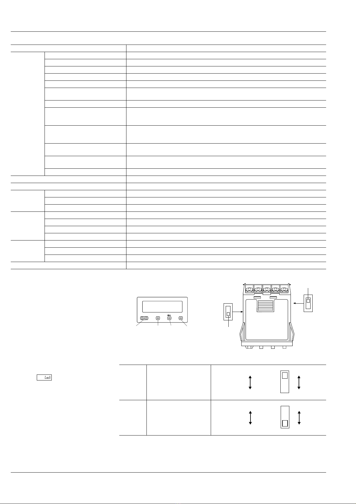
Un-Lock LockPress the SET key while pressing
the MODE key.
+
Mode changes as follows by pressing the SET key while holding down the MODE key.
When the lock is set, you cannot enter modes other than
backlight setting mode.
Lit red
Flashes green
Lit green
Flashes red
Press the SET key while pressing
the MODE key.
+
Addition SubtractionPress the SET key while pressing
the MODE key.
+
HOLD-A HOLD-B
SHOT-B SHOT-A
Lock mode Backlight setting mode
Output setting mode Input setting mode
Press the SET key while pressing
the MODE key.
+
2) Lock mode
3) Backlight setting mode
4) Input setting mode
5) Output setting mode
Front panel reset key
Regular operation mode
Preset
value Count value Output
change
Lock
mode ×× ×
Backlight
setting
mode
×× ×
Input
setting
mode
×
Addition: “0”
Subtraction:
“Preset value”
ON➝OFF
Output
setting
mode
×
Addition: “0”
Subtraction:
“Preset value”
ON➝OFF
Changing the preset value
1. It is possible to change the preset
value even during counting. However,
be aware of the following points.
1) If the preset value is changed to less
than the count value with counting set to
the addition direction, counting will
continue until it reaches full scale, returns
to zero, and then reaches the new preset
value. If the preset value is changed to a
value above the count value, counting will
continue until the count value reaches the
new preset value.
2) Suppose that the counter is preset to
count down.Whether a preset count down
value is smaller or larger than the count
value, the counter counts down to “0
(zero)”.
2. If the preset value is changed to “0”,
the counter will not complete count-
up. It starts counting up when the
counting value comes to “0 (zero)”
again.
1) Addition (up-count) input when
counting is set to the addition direction,
counting will continue until full scale is
reached, return to zero, and then
complete count-up.
2) Subtraction (down-count) input when
counting is set to the subtraction direction,
counting will continue until full scale
“–9999999”is reached, and then the
display will change to “”.
LC2H_Preset.fm Seite 82 Freitag, 11. Juni 2004 9:34 09