2/2
2. Mounting
1. Remove the bottom case.
Insert the driver and slightly turn.
* Do not insert the screw driver too deep.
Doing so may cause the claw to be broken.
Attention
Mounting the bottom case
• Tighten the screws securely until the screw heads touch the bottom case.
(Otherwise, loose screw heads may hit the PCB and cause malfunction
when mounting the top case.)
• Do not over-tighten the screws.
(The bottom case may be deformed, resulting in fall of the unit.)
Connecting the remote control wiring
• Arrange the wires as shown in the illustration for 6in step 2 (P.14 - 15) and
5(P.16 - 17), avoiding unnecessary wires being stored in the case.
• Avoid the wires touching parts on the PCB.
• Avoid the wires coming in contact with the metallic object protruded from
the PCB.
(Caught wires may destroy the PCB.)
Mounting the top case
• Do not push the top case with excessive force.
(Doing so may cause the protrusions of the bottom case to hit and destroy
the PCB.)
2. Mount to the wall.
Exposed type
Claw
(2 places)
Screw
(supplied)
Hole for
screw Claw (2 places)
Avoid the wire
being caught.
Top case
(Back side)
Bottom case
(Back side)
Terminal board
150 mm
6 mm
1
2
7
3
6
4
5
1 Make 2 holes for screws using a driver.
2 Mount the bottom case to the wall.
3 Cut here with a nipper and remove the burr with a file.
4 Remove the sheath. Approx. 150 mm
5 Remove the coating. Approx. 6 mm
6 Connect the remote control wiring.
• Make sure the wiring connection is in the correct direction.
• Arrange the wires along the groove of the case.
• Avoid the wire being caught.
7 Mount the top case.
• Align the claws of the top case and then align the claws of the bottom case.
Flat-blade
screwdriver Bottom
case
Embedded type
Claw
(2 places)
Screw
(supplied)
Hole for
screw Claw (2 places)
Avoid the wire
being caught.
Top case
(Back side)
Bottom case
(Back side)
Terminal board
50 mm
6 mm
1
2
3
6
4
5
1 Make 2 holes for screws using a driver.
2 Mount the bottom case to the wall.
• Pass the wire through the hole in the centre of the bottom case.
3 Remove the sheath. Approx. 50 mm
4 Remove the coating. Approx. 6 mm
5 Connect the remote control wiring.
• Make sure the wiring connection is in the correct direction.
• Avoid the wire being caught.
6 Mount the top case.
• Align the claws of the top case and then align the claws of the bottom case.
3. Setting/Test Operation/Specifications
Setting
Clock
RC. setting mode (Main/sub, Clock type)
Detailed setting mode (Ventilation fan output setting, Room temperature sensor, Temperature display setting)
Clock
1. Press and hold for several seconds.
2. Set day of the week, hour and minute.
The indicator illuminates after blinking. Press .
Code no. Item Set data
0000 0001
31 Ventilation fan output setting Not connected Connected
32 Room temperature sensor Main unit RC
33 Temperature display setting °C °F
Test operation
Turn on the circuit breaker beforehand, referring to the operating instructions for the unit. The remote controller starts.
1. Press and hold for several seconds.
[TEST] display appears. (The unit enters the test operation mode.)
2. Press . Perform the test operation.
[TEST] is displayed during the test operation.
3. Press .Finish the test operation.
[TEST] display disappears.
4. Delete the error history.
Press and hold the 2 buttons for several seconds simultaneously. ,
[Information of errors is displayed.
To delete the error history, press .
Press to finish service mode.
Attention
• Do not use this mode for purposes other than the test operation.
(To prevent overload of the units)
• Read the installation instructions supplied with the units.
• Any of the Heat, Cool and Fan operations can only be performed.
• Temperature cannot be changed.
• The test operation mode is automatically turned off in 60 minutes. (To prevent continuous test operation)
• Outdoor units do not operate for approx. 3 minutes after the power is turned on or operation is stopped.
Specifications
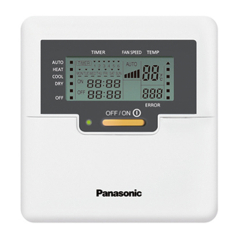
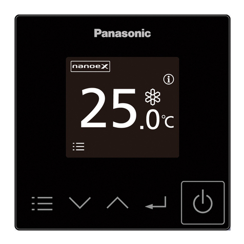
Model No. CZ-RTC4A
Dimensions (H) 120 mm × (W) 120 mm × (D) 20 + 4.75 mm
Weight 160 g
Temperature/Humidity range 0 °C to 40 °C / 20 % to 80 % (no condensation) *Indoor use only.
Power Source DC16 V (supplied with indoor unit)
Clock
Precision ± 30 seconds/month (at normal temperature 25 °C)
*Adjust periodically.
Holding time 24 hours (when fully charged)
*Approx. 8 hours are required for full charge.
Number of connected indoor units Up to 8 units
4. List of Compatible Indoor Unit with CZ-RTC4A
Indoor unit which connects to CZ-RTC4 can be connected to CZ-RTC4A
S-22MU2E5BN S-160MF3E5AN S-22MZ1H4A S-56MD1E5 S-71MP1E5 S-250PE3E5B S-30PU1H5B S-30PT3Q S-18PU3ZA S-50PU1H5
S-28MU2E5BN S-22MF3E5AN S-28MZ1H4A S-73MD1E5 S-180ME3H5 S-180PE4R S-36PU1H5B S-34PT3Q S-24PU3ZA S-22PT1H5
S-36MU2E5BN S-28MF3E5AN S-36MZ1H4A S-22ML1E5 S-224ME3H5 S-200PE4R S-42PU1H5B S-43PT3Q S-3443PU3ZA S-28PT1H5
S-45MU2E5BN S-36MF3E5AN S-45MZ1H4A S-28ML1E5 S-280ME3H5 S-224PE4R S-50PU1H5B S-48PT3Q CS-F18DB4E5 S-35PT1H5
S-56MU2E5BN S-45MF3E5AN S-56MZ1H4A S-36ML1E5 S-3650PU3E S-200PE4E S-1821PU3H S-3448PT3Q CS-F24DB4E5 S-45PT1H5
S-60MU2E5BN S-56MF3E5AN S-60MZ1H4A S-45ML1E5 S-6071PU3E S-250PE4E S-2430PU3H S-18PU3QA CS-F28DB4E5 S-55PT1H5
S-73MU2E5BN S-60MF3E5AN S-73MZ1H4A S-56ML1E5 S-1014PU3E S-19PU1H5C-1 S-3448PU3H S-21PU3QA CS-F34DB4E5 S-24PU2V6-6
S-90MU2E5BN S-73MF3E5AN S-36MT2E5A S-73ML1E5 S-25PY3E S-25PU1H5C-1 S-1821PF3H S-24PU3QA CS-F43DB4E5 S-34PU2V6-6
S-112MU2E5BN S-90MF3E5AN S-45MT2E5A S-22MR1E5 S-36PY3E S-30PU1H5C-1 S-2430PF3H S-34PU3QA CS-F50DB4E5 S-48PU2V6-6
S-140MU2E5BN S-106MF3E5BN S-56MT2E5A S-28MR1E5 S-50PY3E S-36PU1H5C-1 S-3448PF3H S-43PU3QA S-18PU2A5 S-34PT2V6-6
S-160MU2E5BN S-140MF3E5BN S-73MT2E5A S-36MR1E5 S-60PY3E S-42PU1H5C-1 S-1821PT3H S-48PU3QA S-21PU2A5 S-48PT2V6-6
S-15MY3E S-160MF3E5BN S-106MT2E5A S-45MR1E5 S-3650PF3E S-50PU1H5C-1 S-2430PT3H S-3448PU3QA S-24PU2A5 S-18PU2Q6
S-22MY3E S-22MF3E5BN S-140MT2E5A S-56MR1E5 S-6071PF3E S-55PU1H5C-1 S-3448PT3H S-18PT3QA S-30PU2A5 S-21PU2Q6
S-28MY3E S-28MF3E5BN S-106MK2E5A S-71MR1E5 S-1014PF3E S-1821PU3H-1 S-1821PU3HA S-21PT3QA S-34PU2A5 S-24PU2Q6
S-36MY3E S-36MF3E5BN S-22MK2E5A S-106ME1E5 S-3650PT3E S-2430PU3H-1 S-2430PU3HA S-24PT3QA S-43PU2A5 S-30PU2Q6
S-45MY3E S-45MF3E5BN S-28MK2E5A S-140ME1E5 S-6071PT3E S-3448PU3H-1 S-3448PU3HA S-34PT3QA S-48PU2A5 S-34PU2Q6
S-56MY3E S-56MF3E5BN S-36MK2E5A S-224ME1E5 S-1014PT3E S-1821PU3HA-1 S-18PU3Q S-48PT3QA S-18PT2A5 S-43PU2Q6
S-106MF2E5A8 S-60MF3E5BN S-45MK2E5A S-280ME1E5 S-3650PK3E S-2430PU3HA-1 S-21PU3Q S-3448PT3QA S-21PT2A5 S-48PU2Q6
S-140MF2E5A8 S-73MF3E5BN S-56MK2E5A S-73ME1E5 S-6010PK3E S-3448PU3HA-1 S-24PU3Q S-18PU3TA S-24PT2A5 S-18PT2Q6
S-160MF2E5A8 S-90MF3E5BN S-73MK2E5A S-140MH1H5 S-100PK3R S-18PU3HB S-30PU3Q S-24PU3TA S-30PT2A5 S-21PT2Q6
S-22MF2E5A8 S-22MM1E5A S-22MK2E5A-1 S-224MH1H5 S-60PE3R S-2124PU3HB S-34PU3Q S-30PU3TA S-34PT2A5 S-24PT2Q6
S-28MF2E5A8 S-28MM1E5A S-28MK2E5A-1 S-280MH1H5 S-71PE3R S-3448PU3HB S-43PU3Q S-3648PU3TA S-43PT2A5 S-30PT2Q6
S-36MF2E5A8 S-36MM1E5A S-36MK2E5A-1 S-180ME2E5 S-100PE3R S-18PF3HB S-48PU3Q S-18PF3T S-48PT2A5 S-34PT2Q6
S-45MF2E5A8 S-45MM1E5A S-45MK2E5A-1 S-224ME2E5 S-125PE3R S-2124PF3HB S-3448PU3Q S-24PF3T S-18PU1H5 S-43PT2Q6
S-56MF2E5A8 S-56MM1E5A S-56MK2E5A-1 S-280ME2E5 S-140PE3R S-3448PF3HB S-1821PF3Q S-30PF3T S-22PU1H5 S-48PT2Q6
S-60MF2E5A8 S-22MM1E5A-1 S-73MK2E5A-1 S-22MP1E5 S-160PE3R S-1821PT3H-8 S-2430PF3Q S-3648PF3T S-25PU1H5
S-73MF2E5A8 S-28MM1E5A-1 S-106MK2E5A-1 S-28MP1E5 S-180PE3R5B S-2430PT3H-8 S-3448PF3Q S-18PT3T S-28PU1H5
S-90MF2E5A8 S-36MM1E5A-1 S-28MD1E5 S-36MP1E5 S-200PE3R5B S-3448PT3H-8 S-18PT3Q S-24PT3T S-30PU1H5
S-106MF3E5AN S-45MM1E5A-1 S-36MD1E5 S-45MP1E5 S-224PE3R5B S-19PU1H5B S-21PT3Q S-30PT3T S-40PU1H5
S-140MF3E5AN S-56MM1E5A-1 S-45MD1E5 S-56MP1E5 S-200PE3E5B S-25PU1H5B S-24PT3Q S-3648PT3T S-45PU1H5
*Please consult to authorize dealer for the connection with older generation of Indoor unit series.
ENGLISH
ACXF60-54230-AA
PRINTED IN CHINA


