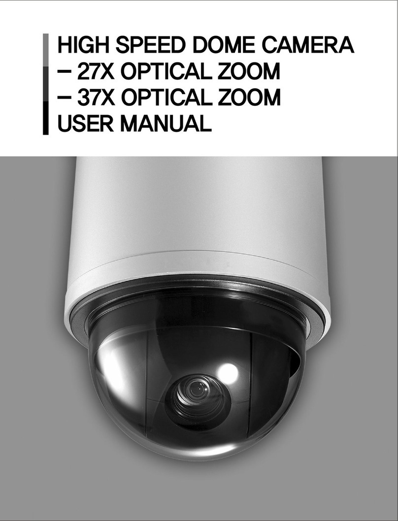
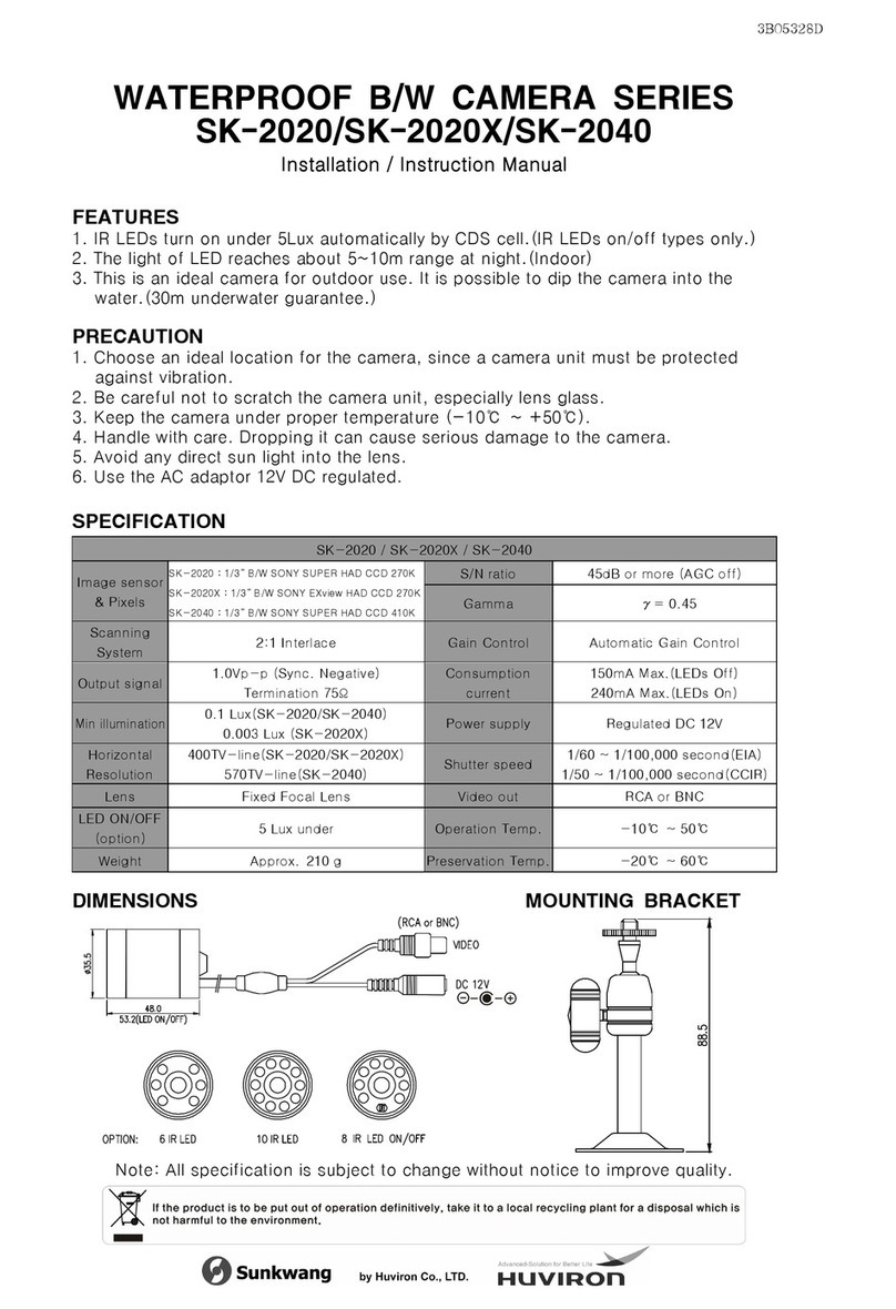
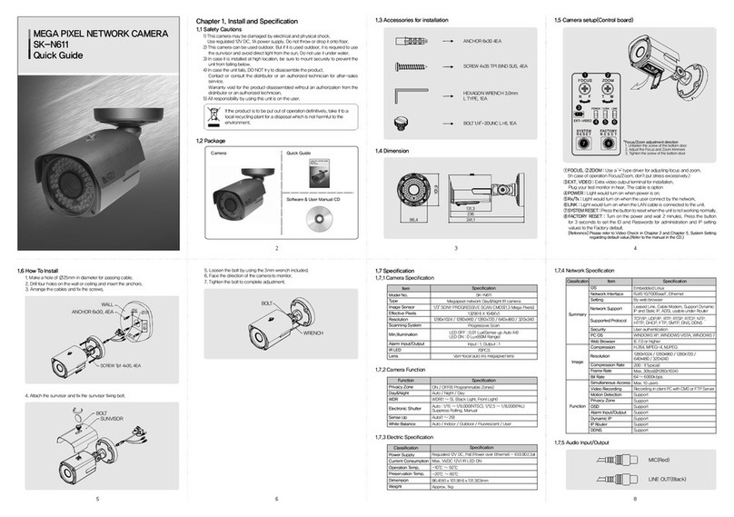
Huviron SK-V207IR-Z946 User manual

IR SPEED DOME CAMERA
USER MANUAL

Please read the instructions carefully for correct use of the product and preserve it for
reference purposes. This specification is subject to change without any prior notice to
improve the quality.
If the product is to be put out of operation definitively, take it to a local
recycling plant for a disposal which is not harmful to the environment.

3
Chapter
<Chapter 1. Warning and Cautions>
<Chapter 2. Overview >
<Chapter 3. How to install>
<Chapter 4. Menu configuration and operating>
1.1 Warning and Cautions ............................................................................................ 6
1.2 Warning ................................................................................................................ 7
1.3 Cautions ............................................................................................................... 8
2.1 Features .............................................................................................................. 10
2.2 Accessories ......................................................................................................... 11
2.3 Designation ......................................................................................................... 12
3.1 How to install ........................................................................................................ 17
4.1 PRESET .............................................................................................................. 23
4.2 MOTION CONTROL .............................................................................................. 28
4.3 TIME SET ............................................................................................................ 33
1.1.1 Examples of sign ......................................................................................................... 6
1.1.2 Examples of sign ........................................................................................................ 6
4.1.1 PRESET .................................................................................................................... 23
4.1.2 MOTION DETECTION ................................................................................................ 25
4.1.3. PRESET XXX CAMERA SET ................................................................................... 26
4.2.1. AUTO SCAN ............................................................................................................ 28
4.2.2 SEQ SCAN ............................................................................................................... 29
4.2.3 RANDOM SCAN ...................................................................................................... 29
4.2.4 PATTERN SCAN ....................................................................................................... 30
4.2.5 TIME SCHEDULE ...................................................................................................... 31
4.3.1 TIME SET SETTING .................................................................................................. 33

4.4 PRIVACY ZONE .................................................................................................... 34
4.5 ALARM IN ........................................................................................................... 36
4.6 ALARM OUT ....................................................................................................... 37
4.7 SETUP ................................................................................................................ 38
4.8 SYSTEM .............................................................................................................. 47
5.1 Dimension ............................................................................................................ 51
5.2 Specification ........................................................................................................ 52
PELCO-D Extended Command ................................................................................. 53
Troubleshooting ........................................................................................................ 54
Warranty Card .......................................................................................................... 55
4.4.1 PRIVACY MASK SETTING ........................................................................................ 34
4.5.1 ALARM IN SETTING ................................................................................................. 36
4.7.1 CAMERA SETUP ...................................................................................................... 38
4.7.2 PAN/TILT SETUP ...................................................................................................... 43
4.7.3 DISPLAY SETUP ...................................................................................................... 44
4.8.1 STEP OUT ................................................................................................................ 49
<Chapter 5. Specification>
<Supplement>
4
Chapter

Chapter 1.
Warning and Cautions
1.1 Warning and Cautions 6
1.2 Warning 7
1.3 Cautions 8
...........................
...............................................................
.............................................................

1.1 Warning and Cautions
Please carefully check these particulars for the safe use.
1.1.1 Examples of sign
1.1.2 Examples of sign
6
Chapter 1. Warning and Cautions
This symbol indicateds the prohibition of disassembly.
This symbol indicates to observe plug off.
This symbol indicates the warning of electric shock.
CAUTION This symbol indicates the cause of equipment
damage.
This symbol indicates the cause of death or serious
injury to the user.
WARNING

1. Warning2
7
Install the product on firm and durable position.
Use a recommended adaptor by the manual.
Unplug the unit when there is any sign of electric leakage,
short circuit or smog by burn.
Do not disassemble or remodel the product.
Please check the external terminal before connecting the
signal cables
WARNING
Chapter 1. Warning and Cautions

1. Caution3
This product should be installed by expert installer.
Do not install the product at the position exposed to the direct sun.
Do not install the product where lighting is unstable.
Do not drop, hit strongly nor vibrate the product.
Please use the product at the proper environment as follow.
- Temperature : -20℃ ~ 60℃(-4℉ ~ 140℉)
- Humidity : below 90%
This product is produced only for the power as follow.
*Be sure to connect power after all installation are completed.
- Current consumption : 12V DC ±10%/18W, Max 2A
24V AC ±10%/18W, Max 1.5A
Unplug it when any inflammable or conductive material
goes into the product.
Caution
8
Chapter 1. Warning and Cautions

Chapter 2.
Overview
2.1 Features 10
2.2 Accessories 11
2.3 Designation 12
............................................................
...................................................
...................................................

2.1 Features
1) 360°continuous rotation, -5°~ 185°tilting range and High-speed pan & tilt at
2) Up to 128 preset
3) Pan position auto compensation(Min 0.08°detection)
4) Day & Night function(ICR)
5) 40pcs of IR LEDs.
6) Real Time Clock function
7) Schedule
8) Alarm input/Alarm output
9) Motion Detection function
10) RS-485
11) Warm up & Cooling
12) Prevent diffused reflection from the IR LED
- This is the high speed dome camera which has wide speed range.
- Speed is controlled by user's option or the zoom magnification.
- This function provides preset camera settings such as pan, tilt, zoom and focus,
which supports up to 128 presets.
- If the pan get out of the position by external factor, this function will find a right
position.
- This function provides automatic mode changeover by sensing day or night conditions.
- The camera equipped with 40pcs of IR LEDs. It can capture clear images as far as
30m away even in total darkness.
- Inside the camera adopted RTC function and battery, it can be save current time.
- Schedule enables you to schedule a sequencing action by day and time.
- A maximum of 8 schedule can be set.
- Sensor can connect to alarm input to detect motion from outside.
- Alarm output supports "relay out" and "Open collector output".
- This camera provides "Motion detection" function.
- The function of the camera can be controlled by RS-485.
- If the air temperature is low or high, the camera warm up or cool down due to the
camera detect the air temperature using temperature sensor.
- The camera separated with IR LED, It can be prevent diffused reflection perfectly.
10
Chapter 2. Overview
250°/sec

2.2 Accessories
11
SCREW 4x35 Tp1, BIND SUS, 4EA
ANCHOR 6x35, 4EA
MOUNT SCREW M5x10, "-"TYPE, BRASS, 1EA
DRIVER TORX T10x105mm, 1EA
TERMINAL 15EDGR-3.81-7P, FMALE
TERMINAL 15EDGR-3.81-5P, FMALE
MANUAL
CAMERA
CONVERT CABLE
MOUNT HOLE STICKER, 1EA
Chapter 2. Overview

2.3 Designation
2.3.1 Configuration
12
BASE TRAY
BODY
Chapter 2. Overview

2.3.2 Camera configuration
① Termination switch : Used for RS485 connection
② Protocol setting switch
- ON : Set on the last camera for 1:1 or multi communication between Camera and
PC or a controller.
- OFF : Set on all cameras except for the last camera for multi-communication.
- Termination setting is as described on <Table 2-1>.
- Protocol can be set manually or automatically.
- Upon selecting " Protocol Auto Detect" function, protocol will be selected automatically.
- Protocol setting is as described on <Table 2-2>.
[Table 2-1] Termination switch
Termination
ON
OFF
SW1
ON
OFF
[Table 2-2] Protocol setting switch
Protocol
Auto
SK-P
Pelco-D
SW2
OFF
ON
OFF
SW3
OFF
OFF
ON
Switch setup
"A"
<Detail "A">
SW8
Reset
ON
OFF
OFF
O N
SW7
NTSC/PAL
NTSC
PA L
NTS C/PA L sett ing
CR2032
3V
+
1 2 3 4 5 6 7 8
1 2 3 4 5 6 7 8
2 50V 3A
ON
OFF
ON
OFF
CA ME RA ADR ESS
FU NCTION S
OFF
ON
SW 1
Te r mination
O n
O f f
TE RM IN AT I ON s et ting
OFFOFF
OFF
OFFON
ON
SW 2 SW3
P r ot oc o l
Auto
S K-P
P elc o- D
P ROT OC OL s e tt ing
OFFOFF
OFF
OFFON
ON
ON
ON
SW 4 SW5
B au d ra te
9 600b ps
2 400b ps
1 9 20 0 bps
4 800b p s
BAUD R ATE s ett in g
1
2
3
4
5
FACTORY DEFAU LT
TOG GLE
SW IT CH
6
7
13
Chapter 2. Overview

③ Baud rate setting switch
④ NTSC/PAL setting switch
⑤ Factory default switch
⑥ Camera address switch
- Select baud rate.
- Baud rate setting is as described on <Table 2-3>.
- ON : NTSC
- OFF : PAL
- Please refer to <Table 2-4>.
- This is switch for camera reset.
- If reset is done at the switch "on", from next time it will be off.
- Factory default table is as follow.
- It is to set camera ID to connect multiple cameras.
- Max. 255 of camera IDs(as binary notation) are available.
- Camera ID setting is as described on <Table 2-6>
[Table 2-3] Baud rate setting switch
Baudrate
2400 bps
4800 bps
9600 bps
19200 bps
SW3
OFF
ON
OFF
ON
SW4
OFF
OFF
ON
ON
[Table 2-4] NTSC/PAL setting switch
NTSC/PAL
NTSC
PAL
SW1
ON
OFF
[Table 2-5] Factory default switch
RESET
ON
OFF
SW8
Toggle Switch
14
Chapter 2. Overview

⑦ Safety Fuse
- It prevent overflow of electricity for safety.(250V, 3A)
1
2
3
4
5
6
7
8
9
10
11
12
13
14
15
16
17
18
19
20
21
22
23
24
25
26
27
28
29
30
31
SW1Camera ID SW2 SW3 SW4 SW5 SW6 SW7 SW8
[Table 2-6] Camera address setting switch
ㆍ
ㆍ
The rest is omitted.
OFF
ON
ON
OFF
OFF
ON
ON
OFF
OFF
ON
ON
OFF
OFF
ON
ON
OFF
OFF
ON
ON
OFF
OFF
ON
ON
OFF
OFF
ON
ON
OFF
OFF
ON
ON
OFF
OFF
OFF
ON
ON
ON
ON
OFF
OFF
OFF
OFF
ON
ON
ON
ON
OFF
OFF
OFF
OFF
ON
ON
ON
ON
OFF
OFF
OFF
OFF
ON
ON
ON
ON
OFF
OFF
OFF
OFF
OFF
OFF
OFF
ON
ON
ON
ON
ON
ON
ON
ON
OFF
OFF
OFF
OFF
OFF
OFF
OFF
OFF
ON
ON
ON
ON
ON
ON
ON
ON
OFF
OFF
OFF
OFF
OFF
OFF
OFF
OFF
OFF
OFF
OFF
OFF
OFF
OFF
OFF
ON
ON
ON
ON
ON
ON
ON
ON
ON
ON
ON
ON
ON
ON
ON
ON
OFF
OFF
OFF
OFF
OFF
OFF
OFF
OFF
OFF
OFF
OFF
OFF
OFF
OFF
OFF
OFF
OFF
OFF
OFF
OFF
OFF
OFF
OFF
OFF
OFF
OFF
OFF
OFF
OFF
OFF
OFF
OFF
OFF
OFF
OFF
OFF
OFF
OFF
OFF
OFF
OFF
OFF
OFF
OFF
OFF
OFF
OFF
OFF
OFF
OFF
OFF
OFF
OFF
OFF
OFF
OFF
OFF
OFF
OFF
OFF
OFF
OFF
OFF
OFF
OFF
OFF
OFF
OFF
OFF
OFF
OFF
OFF
OFF
OFF
OFF
OFF
OFF
OFF
OFF
OFF
OFF
OFF
OFF
OFF
OFF
OFF
OFF
OFF
OFF
OFF
OFF
OFF
OFF
ON
OFF
ON
OFF
ON
OFF
ON
OFF
ON
OFF
ON
OFF
ON
OFF
ON
OFF
ON
OFF
ON
OFF
ON
OFF
ON
OFF
ON
OFF
ON
OFF
ON
OFF
ON
15
Chapter 2. Overview

Chapter 3.
How to install
3.1 How to install 17
................................................

3.1 How To Install
1) After loosing the fixing screw by supplied Torx driver, separate the body from the
base tray.
2) Remove the guide pin on the back side then fasten the fixing screw instead of guide
pin.(※Caution : If you don't get rid of the guide pin, The camera can't move.)
17
MOUNT
SCREW
GUIDE PIN
Chapter 3. How to install

3) Open the switch door by "-" driver then adjust the switch. After finish setting, close
the door.
4) Make a hole using supplied "MOUNT HOLE STICKER" after that put the cable in the hole.
18
MOUNT
HOLE
STICKER
RS-485
VIDEO
SENSOR
<DETAIL "A">
POWER
ADAPTOR
CABLE
"A"
Chapter 3. How to install

5) Firstly push in the anchor then fasten four screws to fix the base tray.
6) Hook the safety wire on the frame as below picture and connect a din cable.
(※Caution : You must hook the wire for preventing a falling accident.)
19
MOUNT HOLE STICKER
ANCHOR 6x35 4EA
BASE TRAY
SCREW 4x35 4EA
FRAME
<DETAIL "B">
"B"
Chapter 3. How to install

7) Separate the "TERMINAL BLOCK" and then wire the sensor cable to "Alarm In/Out".
8) Reassemble the base tray with body.
20
"D"
<DETAIL "D">
Put the cable in the hole
Chapter 3. How to install
<DETAIL "C">
5P
Alarm_No
Alarm_Nc
Alarm_Com
GND
Alarm
Relay
Open
Collector
7P
Nc
Nc
GND
Sensor 4
Sensor 3
Sensor 2
Sensor 1
"C"
Table of contents
Other Huviron Security Camera manuals

Huviron
Huviron DC80IR User manual

Huviron
Huviron SK-N611 User manual

Huviron
Huviron SK-P461D/HD21 User manual

Huviron
Huviron SK-P464D/M556AI User manual

Huviron
Huviron SK-D302IR(D)/HD21 User manual

Huviron
Huviron SK-NV221 User manual

Huviron
Huviron SK-V251IR(D) User manual

Huviron
Huviron SK-2020 User manual

Huviron
Huviron SK-P461D/HD21 User manual

Huviron
Huviron SK-B300(D)/HD21 User manual