Panblast BB120S-2 CORSA II Use and care manual

PRODUCT OPERATING MANUAL
PANBLASTTM
BB120S-2 CORSA II ERC4-1 AIRSTOP II
Manual Number: ZVP-PC-0182-00

SECTION
1.
GENERAL INFORMATION
2.
INITIAL SETUP INSTRUCTIONS
3.
OPERATING INSTRUCTIONS
4.
MAINTENANCE
5.
TROUBLE SHOOTING GUIDE
6.
ASSEMBLIES, PARTS LISTING & EXPLODED VIEW
BLAST POT SERIAL NUMBER:

ZVP-PC-0182-00-R0
- 1 -
1.0 GENERAL INFORMATION
1.1 Panblast notice to purchasers and users
1.1.1 All products and equipment designed and
manufactured by Panblast are intended for use
by experienced users of abrasive blasting
equipment and its associated operations and
abrasive blasting media.
1.1.2 It is the responsibility of the user to:
- Determine if the equipment and abrasive
media is suitable for the users' intended
use and application.
- Familiarize themselves with any appropriate
laws, regulations and safe work practices,
which may apply within the users working
environment.
- Provide appropriate operator training and a
safe working environment including
operator protective equipment (PPE) such as,
but not limited to, safety footwear,
protective eyewear and hearing protection.
1.1.3 Panblast Standard Terms and Conditions of Sale
apply. Contact your local Panblast office should
you require any further information or
assistance.
1.2 ! WARNING ! –READ THIS SECTION
CAREFULLY BEFORE USING THIS
EQUIPMENT/APPARATUS.
1.2.1 Heavy metal paint, asbestos and other toxic
material dusts will cause serious lung disease or
death without the use of properly designed and
approved Supplied Air Respiratory equipment
(SAR) by blast operators and all personnel within
the work site area.
1.2.2 The compressor must have adequate output and
the plumbing between the compressor and the
point of attaching the air supply hose must have
sufficient capacity to supply the volume of air at
the pressure required.
1.3 Standard safety precautions
1.3.1 Approved safety eyewear, hearing and footwear
protection should be worn at all times by the
operator and all personnel in the immediate
area that may be exposed to any hazards
generated by the abrasive blasting process.
1.3.2 Suitably approved respiratory protection should
also be worn when handling abrasive media, or
abrasive refuse dust, and when carrying out any
service/maintenance work where any dust may
be present.
1.3.3 Any work performed on electrical wiring or
components must only be carried out by
suitably qualified and registered electrical trades
personnel.
1.3.4 Under no circumstances should any safety
interlocks/lockouts or features be altered or
disabled in any way.
1.3.5 All equipment must be isolated from the
compressed air supply and electrical power prior
to any service or maintenance work being
carried out.
1.3.6 All care must be taken by the operator(s) when
lifting or moving equipment or components in
order to prevent injury. Bulk blaster must always
be emptied of abrasive media before any
attempt is made to move them.
1.3.7 Any modification of the equipment and/or
components or use of non-genuine PanBlast™
replacement parts will void warranty.
1.3.8 Always check the Material Safety Data Sheet
(MSDS) of the abrasive media being used to
ensure that it is free of harmful substances, in
particular, free silica, cyanide, arsenic or lead.
1.3.9 Test the surface to be blasted for harmful
substances, taking the appropriate measures to
ensure the safety of the operator and others.
1.3.10 The operator should carry out a daily inspection
of all related components prior to startup of all
wearing and safety items to ensure they are in
correct operating order. In particular check all
hose couplings and nozzle holders, ensuring
that all hose couplings are fitted correctly and
the safety locking pins are engaged and in good
order. Always install safety whip check cables at
every hose connection. Ensure that the blast
nozzle has been securely screwed into the
nozzle holder and the nozzle holder has been
secured to the blast hose correctly and all
screws are engaged.
NOTE: UNDER OSHA 1915:34(c)(1)(iv) DEAD
MAN CONTROL. A DEADMAN CONTROL
DEVICE SHALL BE PROVIDED AT THE NOZZLE
END OF THE BLAST HOSE EITHER TO PROVIDE
DIRECT CUTOFF OR TO SIGNAL THE POT
TENDER BY MEANS OF A VISUAL AND
AUDIBLE SIGNAL TO CUT OFF THE FLOW, IN
THE EVENT THE BLASTER LOSES CONTROL OF
THE HOSE. THE POT TENDER SHALL BE
AVAILABLE AT ALL TIMES TO RESPOND
IMMEDIATELY TO THE SIGNAL.
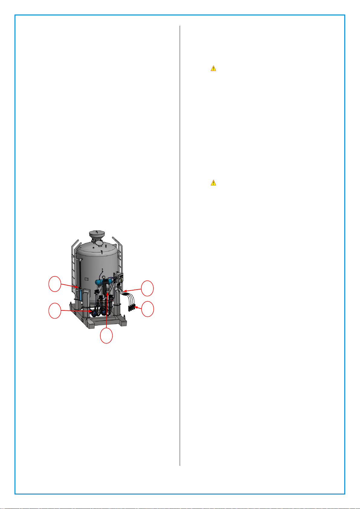
2.0 INITIAL SET UP INSTRUCTIONS
2.1 Bulk blaster initial set up
2.1.1 Position the bulk blaster at the location where it
is to be used, preferably on a flat, level surface.
Never attempt to move the bulk blaster when it
is full of abrasive media.
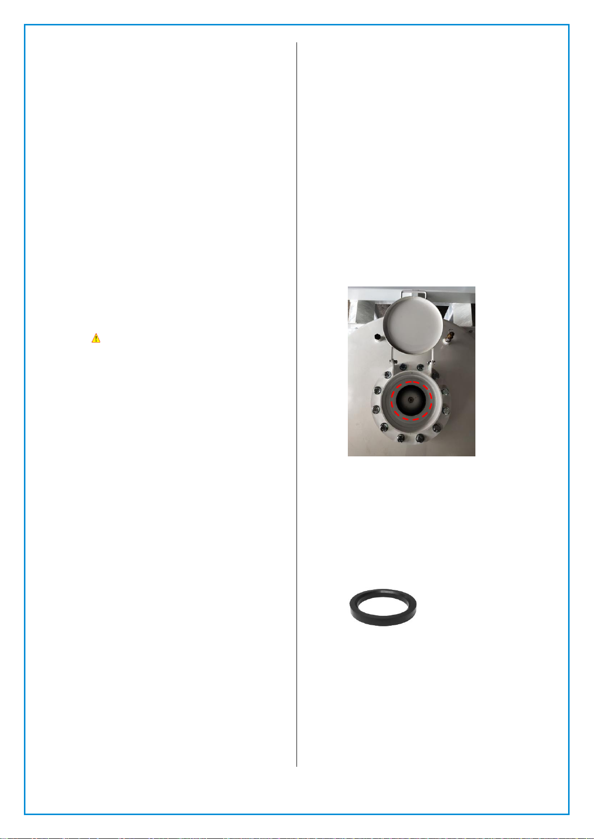
2.1.2 Fit the blast hose coupling and nozzle holder to
the blast hose, ensuring that the ends of the
blast hose are cut square and flat. The blast
hose coupling and nozzle holder must be
pushed/twisted up onto the blast hose until the
end of the blast hose is firmly up against the
inside step located inside the blast hose
coupling and nozzle holder. Then install the
screws supplied with the blast hose coupling
and nozzle holder to ensure that they are
securely fitted to the blast hose.
! WARNING ! –NEVER OPERATE/USE A
BLAST HOSE WITHOUT THE BLAST HOSE
COUPLING AND NOZZLE HOLDER FITTED IN
THE CORRECT MANNER.
2.1.3 Once fitment of the blast hose fittings is
completed, connect the blast hose coupling to
the abrasive metering valve couplings located
on the bottom of the bulk blaster, making sure
that the coupling safety locking pins are
correctly fitted and form an airtight seal
between the two couplings. Then lay the blast
hose out flat for its full length.

ZVP-PC-0182-00-R0
- 2 -
2.1.4 Connect the ends of the electric remote control
cable quick connect couplings to the electric
remote control panel on the bulk blaster shown
in figure (A). Then lay the electric remote
control cables out alongside the blast hose for
its full length.
2.1.5 Using cable ties, heavy tape or similar, attach
the electric remote control cables directly to the
blast hose at approximately 1000mm (40")
intervals. The remote control handle should be
cable tied to the blast hose at a point directly
behind the previously fitted nozzle holder.
2.1.6 Securely attach a suitably sized compressed air
line to the bulk blaster main supply ball valve,
ensuring that the main supply ball valve is in the
closed position. It is preferable for the
compressed air line to be at least one size larger
than the piping size on the bulk blaster. Ensure
that all coupling safety locking pins and/or
locks are correctly fitted to the compressed air
connection. Panblast recommends the use of
correctly sized safety whip check cables to all
compressed air and blast hose connections.
2.1.7 Check that the nozzle holder rubber washer is
correctly installed then screw the blast nozzle
fully into the nozzle holder, ensuring that it
forms a seal against the nozzle holder rubber
washer.
2.1.8 The bulk blaster is now ready for operation.
3.0 OPERATING INSTRUCTIONS
Figure A
3.1 Bulk blaster operating instructions
3.1.1 Ensure that the bulk blaster has been set up as
detailed in section 2.0 of this manual.
3.1.2 Check that the electric remote control cable
connections to the bulk blaster are configured
as outlined in 2.1.4 of this manual.
3.1.3 Check that the main air supply ball valve is in
the closed position and the exhaust ball valve is
in open position
3.1.4 Screw the control knob of the Corsa II Abrasive
Metering Valve in a clockwise direction all the
way in, noting the position of the control knob;
now wind the control knob out in an
anticlockwise direction 4 turns. This provides an
initial starting position.
3.1.5 Load the abrasive media into the bulk blaster by
pouring it in through the posi valve opening
located in the top of the bulk blaster. The bulk
blaster screen (where supplied) should be used
to prevent coarse debris and oversize particles
from entering the bulk blaster.
! WARNING ! –DO NOT OVERFILL THE BULK
BLASTER. THE ABRASIVE LEVEL SHOULD
REMAIN BELOW THE BOTTOM OF THE POSI
VALVE.
3.1.6 Check the remote control handle, and ensure
that the safety flapper is functional for
activation and deactivation.
3.1.7 Check that all hose connections, fittings, safety
locking pins etc. are all secure and in the proper
location.
3.1.8 Start the air compressor, and allow the
compressor to reach the desired operating
pressure. Do not set the blast pressure below
586Kpa (85psi) as the blast system may not
operate correctly (this is to ensure that the posi
valve is fully operational and closes)
! WARNING ! –DO NOT EXCEED THE
MAXIMUM OPERATING PRESSURE (REFER TO
NAMEPLATE AFFIXED TO THE BLAST POT
SHELL) OF THE BULK BLASTER AT ANY TIME
AS THIS COULD RESULT IN SERIOUS INJURY
OR DEATH.
3.1.9 Close the exhaust ball valve (Figure A. No.1)
before opening the main supply ball valve
(Figure A. No.2) on the bulk blaster.
3.1.10 Do not set the blast pressure below 586Kpa (85
psi) as the blast system may not operate
correctly. The posi valve may not pop up and
seal if the pressure is below 85psi.
3.1.11 Check the piping for air leaks.
NOTE: THE BULK BLASTER IS NOW
PRESSURIZED.
THE SYSTEM IS READY TO OPERATE. THE
OPERATOR SHOULD WEAR APPROVED
SUPPLIED AIR RESPIRATORY EQUIPMENT (SAR)
AND APPROPRIATE BODY PROTECTION GEAR
BEFORE ACTIVATING THE BLASTING MACHINE.
3.1.12 Pick up the blast hose at the blast nozzle end,
and direct the blast nozzle at the surface/part
to be abrasive blasted.
3.1.13 Depress the flapper on the remote control
handle and then depress the lever handle. After
a few moments, the Tandem Remote Valve and
the Corsa II Abrasive Metering Valve will activate
and the abrasive blasting process will
commence.
3.1.14 Now run a test blast to check if the Corsa II
Abrasives Metering Valve flow setting is correct,
the flow from the blast nozzle should be slightly
discolored on a light or contrasting background.
3.1.15 If no discoloration is evident and there is a high
pitched sound from the blast nozzle, then the
adjustment is lean and the abrasive flow needs
to be increased by further opening the Corsa II
Valve, this should be done in 1/4 turn
increments in an anticlockwise direction until
the correct abrasive media flow is achieved.
2
3
5
4
1

ZVP-PC-0182-00-R0
- 3 -
3.1.16 If the abrasive feed to the blast nozzle is erratic
and surging, then the feed is too rich and the
abrasive flow needs to be decreased, again in
1/4 turn increments in a clockwise direction
until the correct flow is achieved.
3.1.17 To stop blasting, release the remote control
handle lever. This will de-energize the Tandem
Remote Control Valve and the Corsa II Abrasive
Metering Valve will automatically close, which
will stop both the abrasive and air flow to the
blasting nozzle. The bulk blaster itself will
remain pressurized.
3.2 Shutdown procedure
3.2.1 Close the main air inlet supply ball valve and
open the exhaust ball valve. The bulk blaster
will now depressurize / exhaust the compressed
air within the bulk blaster through the exhaust
muffler
3.2.2 Shut down the air compressor.
3.2.3 Cover the bulk blaster with the lid (where
supplied) and coil up and store the blast hose
and twin line assembly to prevent accidental
damage.
4.0 MAINTENANCE
! WARNING ! –THE COMPRESSED AIR
SOURCE MUST BE ISOLATED BEFORE
PERFORMING ANY MAINTENANCE WORK.
FAILURE TO DO SO MAY CAUSE SERIOUS
INJURY OR DEATH.
4.1 On a daily basis
4.1.1 If fitted, drain any water/moisture from the
moisture separator by opening the mini drain
valve located on the bottom of the moisture
separator.
NOTE: IT IS RECOMMENDED THE INCOMING
COMPRESSED AIR IS EQUIPPED WITH A DRYER
SYSTEM TO ENSURE THE INLET AIR IS DRY.
4.1.2 Inspect the blast hose for wear by feeling along
its full length for soft spots which indicate wear,
and replace the blast hose as necessary.
4.1.3 Check that all blast hose couplings and the
nozzle holder are secure and that all safety
locking pins are correctly in place.
4.1.4 Remove the safety locking pins and disconnect
the couplings by twisting the coupling counter
clockwise. Inspect the coupling gaskets for wear
and correct seating. Replace the gaskets as
required. Reconnect the coupling by engaging
the lugs with the bulk blaster coupling and
twisting the hose coupling until fully engaged,
and then re-fit the safety locking pins.
4.1.5 Inspect the AirStop II Electric Handle, and check
that the lever and safety flapper assembly
operate correctly, and that the safety flapper
prevents operation of the remote control handle
when in the deactivated position.
4.2 On a weekly basis
4.2.1 Remove the blast nozzle from the nozzle holder
by unscrewing the nozzle in a counter clockwise
direction, and inspect it for wear. Replace the
nozzle when the internal diameter is worn by
1.5mm (1/16") from its original size, or if the
inner carbide liner is chipped or cracked.
4.2.2 Check the condition of the nozzle washer and
replace as required, then re-fit/replace the blast
nozzle by screwing it clockwise into the nozzle
holder until it is fully sealed against the nozzle
washer.
4.2.3 Check the condition of the nozzle holder, and
inspect for any cracks or signs of damage.
Replace if required as detailed in section 2.1.2.
4.3 On a monthly basis
4.3.1 Inspect the posi valve located in the top of the
bulk blaster for wear in the form of cracks or
grooves. If replacement is required, remove the
bulk blaster shell manhole cover located on the
side of the bulk blaster. Unscrew the posi valve,
and remove both the connecting air hose.
Installation of the new posi valve is a reversal of
the removal procedure which ensures that the
posi valve is positioned directly below the top
opening for correct sealing. Refer Figure B.
Figure B
4.3.2 Check and inspect the posi valve urethane
seating ring for wear. If replacement is
necessary, unscrew the metal screw & use a
large screwdriver or similar tool to pry the
seating ring out of the seat. When re-fitting the
new seating ring, ensure that it is correctly
seated within the seat retainer ring and tighten
the screw. It is recommended to replace the
valve plug and seating ring at the same time as
a set. Refer Figure C.
Figure C
4.3.3 Inspect the bulk blaster exhaust muffler and
exhaust line for wear or blockages, replace the
worn or blocked muffler and exhaust line as
necessary.
This manual suits for next models
1
Table of contents
Other Panblast Industrial Equipment manuals