- 2 -
ZVP-PC-0069-00-R1
switch on the right side. Secure the assembly in
position using four (4) of the 1/4" x 3/4" bolts
and nuts provided.
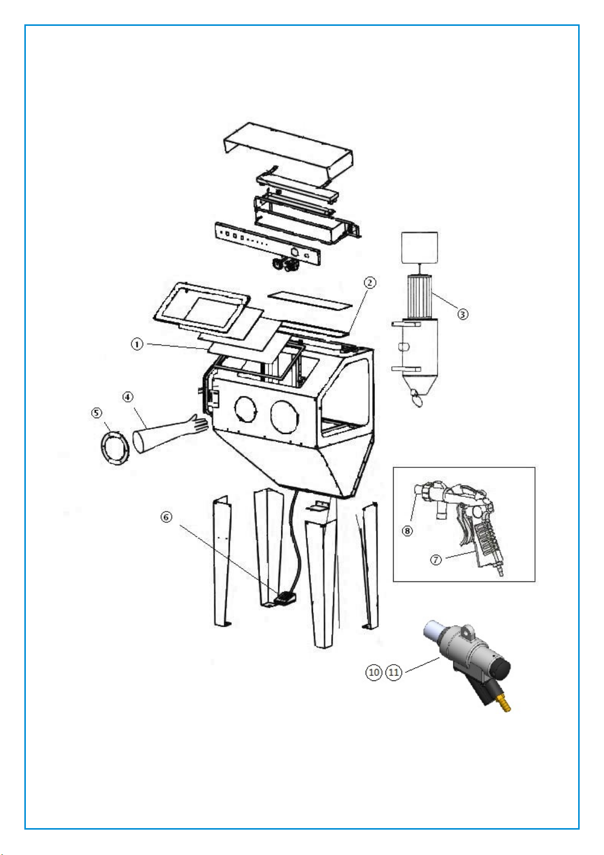
2.11 Attach the dust collector body to the rear panel
(right side) aligning the intake tube with the rear
panel hole. Fix in position using four (4) of the
1/4" x 3/4" bolts provided.
2.12 Place the dust collector motor and filter
assembly into the top of the dust collector body
and lock in position using the 2 latches
provided.
2.13 Remove the inlet box that covers the dust
collector intake tube hole from the rear panel of
the cabinet. Apply a bead caulking around the
tube to seal it, then fit sponge filter media into
box (to protect fan motor from dust) and refit
the inlet box.
2.14 Place the cabinet floor grate into the cabinet
ensuring the corner cut out is located in the
right hand front corner of the cabinet to allow
the suction gun hoses to pass through.
2.15 Check that all securing nuts, bolts and screws
are correctly tightened.
2.16 Connect the dust collector plug into the female
socket coming from the light assembly, and
then connect the plug from the light assembly
into the power supply socket.
2.17 Take the self-locking air connection fitting from
the inner packing. Wrap a thread sealing tape
round the fitting thread. Screw it into the air
inlet hole on the rear side of the electrical
control box and tighten.
2.18 Push the coupler to the self-locking fitting
toward the air inlet hole, the cone shaped end of
the connector will immediately pop out. Fit it
into the air hose connecting to the air
compressor, fasten with a hose clamp. Push the
coupler again and fit in the opposite side of the
cone shaped end, release and the connection is
secure.
2.19 Remove the suction head from the fixed gun
assembly, fit in the air jet, re-connect the
suction head and tighten. Loosen the M6 screw
on the side of the gun and install the
corresponding blast nozzle (orifice size should
be twice the size of the air jet), tighten the
screw.
2.20 Connect the side branch of the gun assembly
with a suction hose. Connect the rear inlet of
the gun to the flexible metal hose in the cabinet,
screw until secure.
2.21 Connect the other end of the suction hose to
the corresponding suction pipe.
2.22 Connect one end of the high pressure air hose
to the air connector on the right side of the
electrical control box, the other end to the air
inlet on the movable gun, secure with hose
clamps.
2.23 Connect one end of the suction hose to the side
branch of the movable gun assembly, the other
to the fixed suction pipe.
2.24 Installation of the air jet and nozzle are the
same as the fixed gun assembly.
3.0 OPERATING INSTRUCTIONS
3.1 Cabinet operation
3.1.1 Assemble and install the blast cabinet as
detailed in Section 2.0 of this manual.
3.1.2 The air jet should be approximately half the size
of the nozzle.
3.1.3 Pour abrasive media approximately 18 kg (40lb)
into the cabinet hopper through the side door of
the cabinet.
3.1.4 Turn on the compressed air supply, when the air
pressure reaches 415 Kpa (60 PSI), press the
power switch to “ON”, the power indicator
should then light up.
! WARNING ! – NEVER EXCEED MAXIMUM
OPERATING PRESSURE OF 125PSI (8.6BAR), AS
THIS MAY RESULT IN SERIOUS INJURY OR
DEATH.
3.1.5 The machine comes with two (2) blasting guns,
but under the control of an electric/pneumatic
system where only one gun is operable at any
one time. When the movable gun and door
closed indicators on the control panel are
illuminated then the movable gun is available
for operation. Step on the pedal switch and the
movable gun shuts down and the fixed gun
operates immediately, this will be seen on the
control panel indicators.
3.1.6 There are limit switches located inside each
door to sense when the doors are open or
closed. If the door closed indicator on the
control panel is not illuminated, the system is
then in a protection mode and the fixed gun will
not operate.
3.1.7 When the air pressure exceeds 60 PSI, the user
can operate the machine. First insert arms into
the rubber gloves, grasp the work piece to be
blasted, position it under the fixed gun, step on
the pedal switch and then the blasting process
begins. Alternately grasp the movable gun,
point the nozzle at the work piece, press the
trigger and the blasting process begins, check
the work piece to ensure the desired result has
been obtained.
3.1.8 The abrasive media will drop into the bottom of
the cabinet hopper to be recycled during the
blasting process.
NOTE: TO ENSURE RELIABLE BLASTING THE
COMPRESSED AIR SHOULD BE DRY, IF IT
CONTAINS TOO MUCH MOISTURE, A
MOISTURE SEPARATOR SHOULD BE
INSTALLED IMMEDIATELY BEFORE THE AIR
ENTERS THE CONNECTION TO THE CONTROL
BOX.
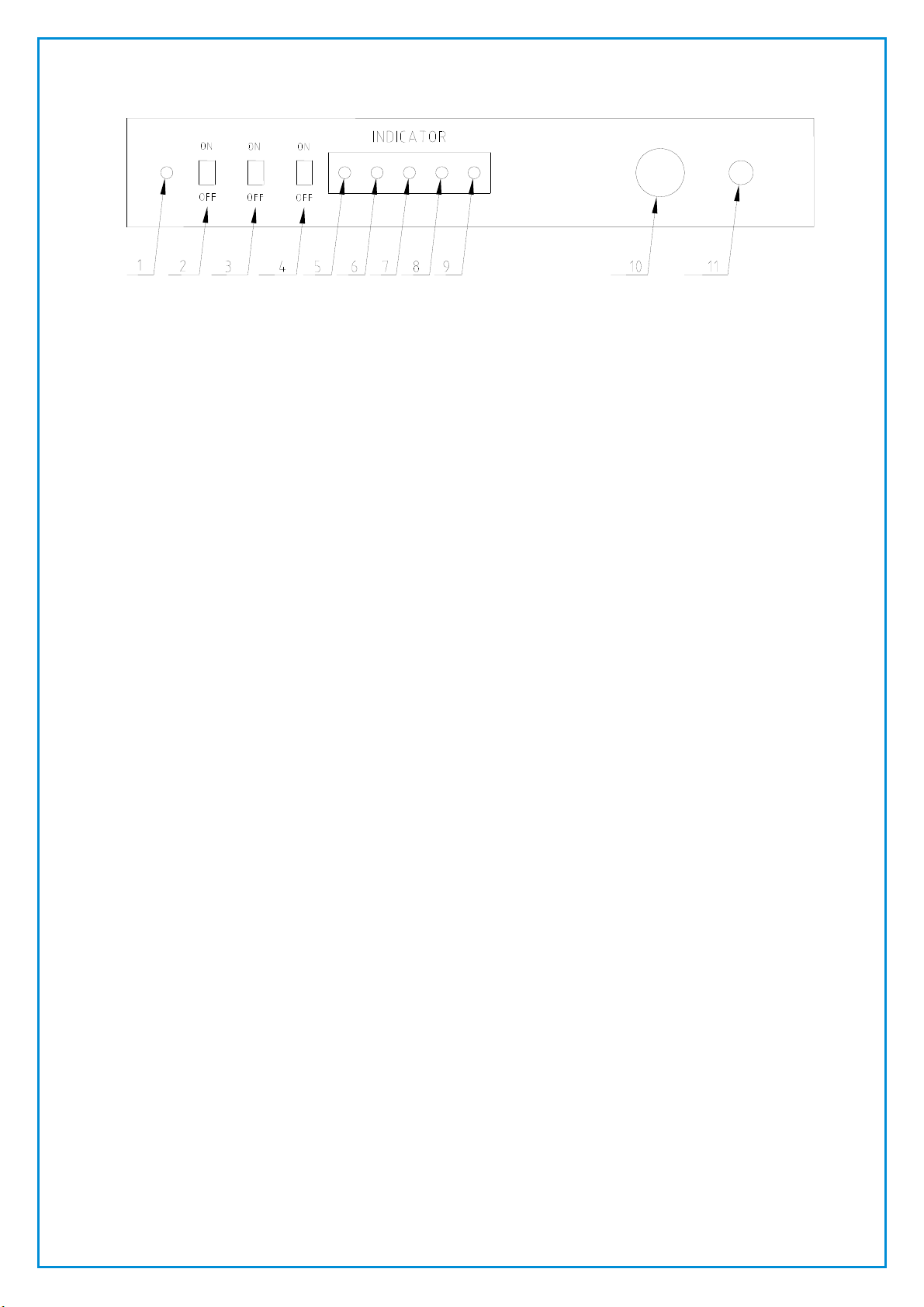
3.2 Illumination and electro-pneumatic system
3.2.1 The pneumatic system is controlled by an
electric circuit, which is set inside the control
box located on top of the cabinet. A layout of
the front panel of the box is shown below in
Figure 1.
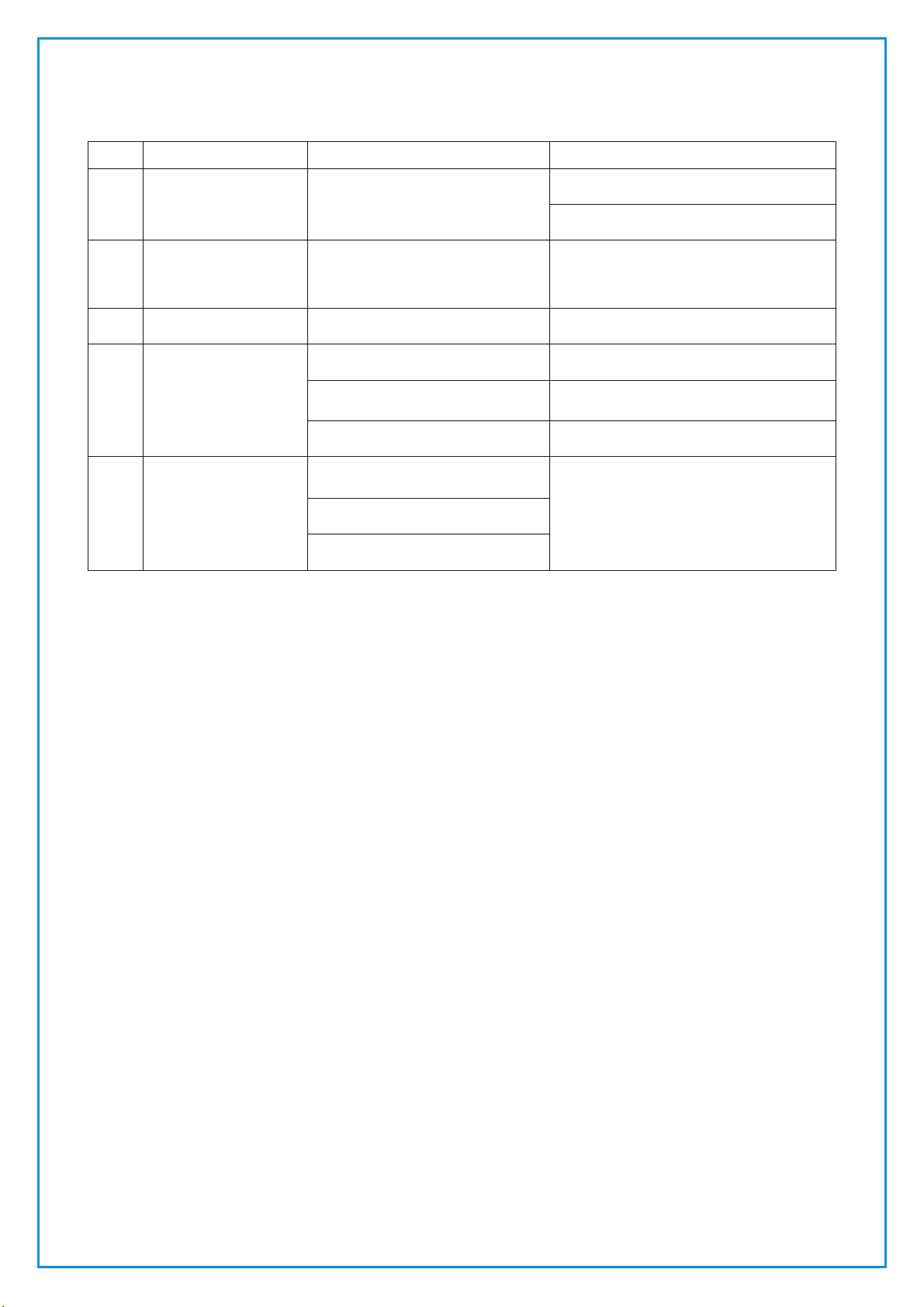
3.3 Control panel functions and indicators