11
10 USER AND INSTALLATION MANUALPANDORA MINI MOTO
SYSTEM FUNCTIONS AND MODES
Security mode
The system confirms arming with 1х sound and 1х light signals. When the system is armed,
the system monitors security zones with separated warning and alarm level of triggering:
• Warning mode - this mode activates when there is a slight impact on the shock sensor or additional
senor. It is accompanied with 1х light and 3х sound signals;
• Alarm mode - this mode activates when a sensor or one of the security zones is triggered. It is 30
sec. light and 30 sec. sound signals. The alarm signals can be cancelled by an arming or
disarming command.
If one of the security zones is triggered the system:
• records this event in it’s non-volatile memory;
• activates the alarm or warning mode;
• informs an owner by all available means;
• blocks the engine (in accordance with the settings and connections).
• If one of the security zones is opened at the moment of arming, the system will produce 4х
sound and 4х light warning signals.
If one of the security zones fails, the system will forcibly turn off this zone. If a switch triggers
more than 9 times in a row, it will be disabled until the next arming. The shock/tilt/motion sensor is
temporarily deactivated (15 sec.) if it has been triggered more than 3 times in a row.
The system confirms disarming with 2х sound and 2х light signals. The system deactivates
engine blocking (if the Immobiliser function and additional blocking are not used). If there were alarm
events (except warning level) during the armed period, the system will produce 4х sound and
4х light warning signals. The system continues to display all zones when it is disarmed, but the
information is not saved in the memory.
!fOr EmErgENcy disarmiNg sEE «cONTrOl ThE sysTEm iN casE Of EmErgENcy». ENgiNE blOckiNg whilE driviNg pOsEs aN
iNcrEasEd risk. wEsTrONgly rEcOmmENd ThaT yOu bE parTicularly carEful whEN usiNg This mEThOd Of blOckiNg.
Security zones
• Outside temperature (status)
• Engine temperature (status)*
• Voltage of the on-board circuits (status)
• Additional sensor (security zone - alarm and warning level)*
• Shock sensor (security zone – alarm and warning level)
• Tilt sensor (security zone – alarm level)
• Motion sensor (security zone – alarm level)
• Turning ignition on (status, security zone – alarm level)
• Pressing brake (status, security zone – alarm level)
• Pressing clutch (status, security zone – alarm level)
• Opening a trunk (status, security zone – alarm level)
!cONTrOl Of ThE sTaTusEs aNd sEcuriTy zONEs dEpENds Of ThE sysTEm sETTiNgs aNd cONNEcTiONs.
* OpTiON.
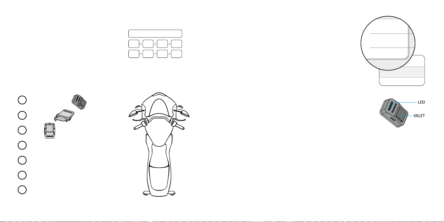
Owner authorization devices and functions
Authorization devices
Authorization devices are Bluetooth devices paired with the system (radio tags, remote controls,
mobile phone with the app, band). The devices are used to recognize an owner in the radio coverage
zone of the base unit, to arm/disarm the system (Hands Free mode) and to implement Immobiliser or
Anti-Hi-Jack functions.
Arming/Disarming by clutch lever
You can arm/disarm the system by a clutch lever if an authorization device is in the coverage zone.
!This mOdE is ENablEd by dEfaulT. iTis rEquirEd TO makE addiTiONal cONNEcTiONs fOr This mOdE
Hands Free arming/disarming
This mode is used for automatic arming/disarming when an owner with an authorization device is
distancing or approaching a vehicle.
!This mOdE is disablEd by dEfaulT. ThE cONfiguraTiON shOuld bE madE by aqualifiEd TEchNiciaN.