Pandora Smart Moto User manual

Pandora would like to thank you
for choosing our service-security system
for motorcycles Pandora Smart Moto/Smart Moto Plus
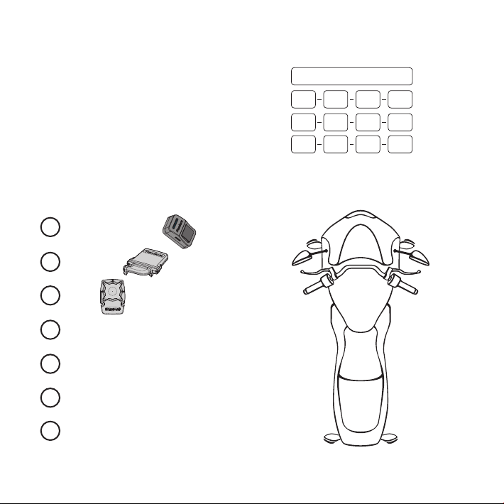
Pandora Smart Moto / Smart Moto Plus is a service-security system built for motorcycles and
quads with on-board voltage of 12V.
It is a complex engineering device, which includes unique and modern technological software and
hardware solutions. While developing we were using the most up-to-date electronics from world’s
best manufacturers. The device is built using high-precision mounting and control machinery; thus,
we guarantee highest possible quality, reliability and stable technical characteristics for the whole
operation period.
The system is built for your convenience: it’s ergonomic, reliable, has the highest security and service
characteristics, 3 years unconditional warranty and free service and support. We are happy to provide
any support we can – feel free to use our online support.
!WARNING! I TIS ST RONGLY RECOMME NDED TO HAVE APROFESS IONA L CAR MECH ANI C TO INSTALL THE SYSTEM . ANY
CAR ELECT RONICS IN STALLE R SHOULD BE ABLE TO INSTALL THE SYSTEM USING IN STALL ATION SCHEME IN TH IS MANUAL
AND THE ALAR M STUD I O OR PAN DORA SPEC IA L IST SOFT WAR E. MOST FEATURES AR E HIG HLY DEPE NDE NT ON COMPETE NT
INSTALL ATION. OUR SYSTEMS AR E THO R OUG HLY TESTED FOR QUAL ITY , SO IF AFE ATU RE FAI LS TO PRODUCE EXPECTED RESULT ,
MOST LIKELY THE PROBLEM IS IN I MP ROPE R INSTALLATION.
This device has limited external factors resistance. It should not be subjected to water beyond occasional splatter.
The base unit is designed to operate at temperatures from -40°C to +85°, the degree of protection is IP54.
The control units (remotes, tags, etc.) are designed to operate at temperatures from -10°C to +40°C, the degree of protection is IP40.
See wiring diagram to nd information about additional devices and options.
Our web-site: pandorainfo.com
Product is in conformity with Electromagnetic Compatibility
Directive EMC 2004/108/EC and R&TTE Directive 1999/5/EC

2PANDORA S M A R T M O T O P L U S
Table of contents
General information 4
System set 4
Read before using 5
PIN-codes of the system 6
System modules layout 6
Owner’s personal card 7
External VALET button 7
Base unit 8
Information signals of the system 9
System functions and modes 11
Security mode 11
Security zones 12
Owner authorization devices and functions 12
Checking the number of paired devices 14
Immobiliser radio tag 15
Functions of the button 15
Indication of the SEND LED 16
Installation/replacing a battery of the tag 16
Prompt entry/change of the main owner phone number 17
Updating rmware of the tag 17
Wrist bracelet PANDORA BAND 18
Switching on/o the Band 18
Charging the Band 18
Button’s functions 19
Firmware update 19
Information icons 20
Control the system by a phone 21
Changing settings via a phone 23

3
USER AND I NSTA LLATION MANUA L
System installation 25
General installation requirements 25
Base unit connectors description 26
Wiring diagram 28
Online service and mobile application 30
Registration 31
Login 31
Adding a system to your account 31
Writing a mobile device to the system memory 32
Control the system 34
Arming 34
Disarming 35
PANIC mode 36
Vehicle search function 37
Season storage mode 37
Service mode 37
Control over the system in case of emergency 39
Emergency disarming 41
Emergency control of the anti-theft functions 41
Programming the system 43
Pandora Specialist Application 44
Pandora Alarm Studio 44
Updating rmware 45
Programming table 46
Additional devices 51
Warranty obligations 52
Installation certicate 55
Acceptance certicate 56
Warranty Card 56

4PANDORA S M A R T M O T O P LU S
GENERAL INFORMATION
System set Pandora Smart Moto and Pandora Smart Moto Plus
1. User and installation manual 1
2. Owner’s personal card 1
3. Immobiliser tag BT-780 1
4. External VALET button 1
5. Base unit with the main cable 1
6. Blocking relay 1
7. Magnetic reed sensor 2
8. Packaging 1
9. External temperature sensor 1
10. Wrist bracelet Pandora Band 1
11. Piezo siren PS-332BT 1
12. Door sensor DMS-100BT 1
!
NOTE! THE MANUFACTURER RESERVES THE RIGHT TO CHANGE THE SYSTEM SET AND CONSTRUCTION OF THE PRODUCT TO IMPROVE
IT’STECHNOLOGICAL AND OPERATIONAL PARAMETERS WITHOUT NOTIFICATION.

5
USER AND I NSTA LLATION MANUA L
Read before using
Carefully read this manual before starting installation and using the security-service system. Pay
attention to the text marked with !
!THE SECURITY-SERVICE SYSTEM IS ACOMPLEX TECHNICAL PRODUCT. SYSTEM INSTALLATION AND CONFIGURATION MUST BE CARRIED
OUT ONLY BY ASKILLED PROFESSIONAL.
!FEATURES AND SYSTEM MODES, CONTROL OF THE VEHICLE’SZONES DEPEND ON THE TYPE OF CONNECTION AND SYSTEM SETTINGS,
ORIGINAL VEHICLE OPERATION LOGIC AND TRIM.
!THE SYSTEM SET INCLUDES THE «OWNER’SPERSONAL CARD». THIS CARD CONTAINS INFORMATION UNDER THE PROTECTIVE LAYER
THAT IS INTENDED ONLY FOR THE OWNER OF THE SYSTEM. MAKE SURE THAT THE PROTECTIVE LAYER ON THE OWNER’SPERSONAL CARD IS
INTACT AFTER THE INSTALLATION OF THE SYSTEM. READ THE «OWNER’SPERSONAL CARD» SECTION OF THIS MANUAL BEFORE ERASING
THE PROTECTIVE LAYER.
!WHEN SYSTEM INSTALLATION IS FINISHED:
• CHECK THE SYSTEM OPERATION AND FUNCTIONS WITH ASPECIALIST.
WERECOMMEND THAT YOU MARK EACH WORKING FUNCTION WITH ASIGN IN THE «CONTROL THE SYSTEM» SECTION.
• CHECK THAT THE «INSTALLATION CERTIFICATE» AND «WARRANTY CARD» ARE FILLED OUT. THESE DOCUMENTS MAY BE REQUIRED FOR
CONTACTING THE CUSTOMER SUPPORT.
• ASK AN INSTALLER TO MARK THE LAYOUT OF THE SYSTEM COMPONENTS ON THE DIAGRAM. THIS INFORMATION MAY BE REQUIRED FOR
DIAGNOSTIC/CONFIGURING OR EMERGENCY DEACTIVATION OF THE SYSTEM.
• WERECOMMEND THAT YOU CHANGE THE DEFAULT VALUE OF THE PIN-CODES.

6PANDORA S M A R T M O T O P L U S
PIN-codes of the system
The «Secret PIN-code»
(is written on the «Owner’s personal card»)
The «Service PIN-code»
(default value is 1-1-1-1)
The «Guest PIN-code»
(default value is 1-2-3-4)
The «Immobiliser PIN-code»
(is used for the Code Immobiliser (pin-to-drive) function)
! ITIS RECOMMENDED THAT YOU WILL WRITE DOWN THE CHANGED OR CREATED VALUES OF ALL PIN-CODES. ELIMINATE THIRD-PARTY
ACCESS TO THIS INFORMATION.
System modules layout
CANNOT BE CHANGED
External VALET button
Base unit
Siren
Circuit being blocked
1
2
3
4
5
6
7

7
USER AND I NSTA LLATION MANUA L
Owner’s personal card
! ERASE THE PROTECTIVE LAYER CAREFULLY. DONOT USE ANY SHARP OBJECTS
TO AVOID DAMAGING OF AHIDDEN INFORMATION UNDER THE PROTECTIVE LAYER.
THE INFORMATION ON THE OWNER’SPERSONAL CARD COULD NOT BE CHANGED
OR RESTORED IN CASE OF DAMAGE OR LOSE. ELIMINATE THIRD-PARTY ACCESS TO
THIS INFORMATION.
The owner’s personal card contains private information under a
protective layer:
• PIN (the «Secret PIN-code») is a 4-digit number. This code
can be used to disarm the system to deactivate Immobiliser
functions and to activate service mode. It can be also used to
enter programming mode.
• LOGIN is a 10-digit number. This information is used to add
the system to the online service and mobile applications.
• PASS contains 8 characters and can consist of digits, lower
and upper case letters). This information is used to add the
system to the online service and mobile applications.
• Phone number is a phone number of the preinstalled SIM card.
External VALET button
An external VALET button with a three-color status LED indicator
is placed inside a vehicle (see the System modules layout).
The button is used for programming the system, arming/
disarming, activating/deactivating Immobiliser mode.
+7-9хх-ххх-хх-хх
1070000000 / Y34aC4vJ
2-2-2-2
LOGIN / PASS
PIN № PHONE NUMBER

8PANDORA S M A R T M O T O P LU S
Base unit
Built-in LTE module (4G LTE/3G/2G | GPS/GLONASS) – provides a connection with our online-
service pandora-on.com and mobile applications), allows to control the system by a phone using DTMF-
commands, voice and SMS notications, LBS-coordinates (only by DTMF–command), automatic date
and time detection, precise GPS location (with Tracking function).
Built-in nano-SIM port is used to work with the built-in GSM modem. The phone number of the
SIM-card installed in the base unit is written on the Owner’s personal card.
!THE SIM-CARD CAN BE CHANGED. THE SIM-CARD SHOULD BE REPLACED AND THE FOLLOWING SETTINGS SHOULD BE PERFORMED
ONLY BY AQULIFIED SPECIALIST.
2.4GHz radio channel, Bluetooth 5.0 protocol (BT5.0) - supports additional Bluetooth devices
(see the «Additional devices» section), including a mobile phone.
Built-in 3D accelerometer is used to detect shock/motion/tilt including 2 separate zones of shock
sensor (alarm and warning), the system allows to adjust sensitivity of each zone, to use data from the
accelerometer to block the engine on movement.
Temperature sensors allow the system to measure temperature of dierent zones: outside
temperature – built-in sensor of the main unit, engine temperature – external temperature sensor.
System allows to change default sensor’s settings, use the information from the temperature sensor of
the DMS-100 BT, program automatic engine start and stop.
Built-in battery allows to notify the owner in case of main power disconnection while system is
armed. The battery will be charged automatically when engine is running.
Built-in micro-USB port – update and conguration of the system using the Pandora Specialist
mobile app or Alarm Studio program.

9
USER AND I NSTA LLATION MANUA L
Information signals of the system
SOUND / LIGHT SIGNALIZATION
SIGNALS
(sound / light) DESCRIPTION
1х /1х Arming
2х /2х Disarming
1х Activating Service mode*
Correct input of the «Immobiliser PIN-code»*
2х Deactivating Service mode*
3х (3 times) A battery in a radio tag is discharged (when turning on the ignition)*
4х (4 times) Absence of the authorization device (whenturning onthe ignition)*
5x /5x Vehicle search
25 sec /25 sec Engine blocking warning in Anti-Hi-Jack mode
30 sec /30 sec Alarm - alarm level of a sensor is triggered,
PANIC mode
3х /1х Warning level of a sensor is triggered
4х /4х «Sensors were triggered» signal when disarming /
«Sensors are triggered» signal when arming
* ADDITIONAL SETTING MUST BE MADE FOR THE SOUND NOTIFICATION (AN ADDITIONAL LOGIC «BEEPER» MUST BE ASSIGNED TO THE
OUTPUT OF THE «SIREN» CHANNEL) - THE CONFIGURATION SHOULD BE MADE BY AQUALIFIED TECHNICIAN.

10 PANDORA S M A R T M O T O P L U S
EXTERNAL BUTTON LED INDICATOR SIGNALS
SIGNALS DESCRIPTION
THE SYSTEM IS ARMED
System is armed
System is armed (authorization devices are in the coverage zone)
Alarm
THE SYSTEM IS DISARMED
Faded System is disarmed
Red System is preparing for the automatic or delayed arming
Green (when turning
on the ignition) System is in Service mode
on the ignition)
on the ignition)
on the ignition)
WHEN ENTERING THE «SECRET PIN-CODE» OR THE «SERVICE PIN-CODE»
PIN-code is incorrect

11
USER AND I NSTA LLATION MANUA L
SYSTEM FUNCTIONS AND MODES
Security mode
The system conrms arming with 1х sound and 1х light signals. When the system is armed,
the system monitors security zones with separated warning and alarm level of triggering:
• Warning mode - this mode activates when there is a slight impact on the shock sensor or additional
senor. It is accompanied with 1х light and 3х sound signals;
• Alarm mode - this mode activates when a sensor or one of the security zones is triggered. It is 30
sec. light and 30 sec. sound signals. The alarm signals can be cancelled by an arming or
disarming command.
If one of the security zones is triggered the system:
• records this event in it’s non-volatile memory;
• activates the alarm or warning mode;
• informs an owner by all available means;
• blocks the engine (in accordance with the settings and connections).
• If one of the security zones is opened at the moment of arming, the system will produce 4х
sound and 4х light warning signals.
If one of the security zones fails, the system will forcibly turn o this zone. If a switch triggers
more than 9 times in a row, it will be disabled until the next arming. The shock/tilt/motion sensor is
temporarily deactivated (15 sec.) if it has been triggered more than 3 times in a row.
The system conrms disarming with 2х sound and 2х light signals. The system deactivates
engine blocking (if the Immobiliser function and additional blocking are not used). If there were alarm
events (except warning level) during the armed period, the system will produce 4х sound and
4х light warning signals. The system continues to display all zones when it is disarmed, but the
information is not saved in the memory.
!FOR EMERGENCY DISARMING SEE «CONTROL THE SYSTEM IN CASE OF EMERGENCY». ENGINE BLOCKING WHILE DRIVING POSES AN
INCREASED RISK. WESTRONGLY RECOMMEND THAT YOU BE PARTICULARLY CAREFUL WHEN USING THIS METHOD OF BLOCKING.

12 PANDORA S M A R T M O T O P LU S
Security zones
• Outside temperature (status)
• Engine temperature (status)
• Voltage of the on-board circuits (status)
• Additional sensor (security zone - alarm and warning level)*
• Shock sensor (security zone – alarm and warning level)
• Tilt sensor (security zone – alarm level)
• Motion sensor (security zone – alarm level)
• Turning ignition on (status, security zone – alarm level)
• Pressing brake (status, security zone – alarm level)
• Pressing clutch (status, security zone – alarm level)
• Opening a trunk (status, security zone – alarm level)
!CONTROL OF THE STATUSES AND SECURITY ZONES DEPENDS OF THE SYSTEM SETTINGS AND CONNECTIONS.
* OPTION.
Owner authorization devices and functions
Authorization devices
Authorization devices are Bluetooth devices paired with the system (radio tags, remote controls,
mobile phone with the app, band). The devices are used to recognize an owner in the radio coverage
zone of the base unit, to arm/disarm the system (Hands Free mode) and to implement Immobiliser or
Anti-Hi-Jack functions.
Arming/Disarming by clutch lever
You can arm/disarm the system by a clutch lever if an authorization device is in the coverage zone.
!THIS MODE IS ENABLED BY DEFAULT. ITIS REQUIRED TO MAKE ADDITIONAL CONNECTIONS FOR THIS MODE
Hands Free arming/disarming
This mode is used for automatic arming/disarming when an owner with an authorization device is
distancing or approaching a vehicle.
!THIS MODE IS DISABLED BY DEFAULT. THE CONFIGURATION SHOULD BE MADE BY AQUALIFIED TECHNICIAN.

13
USER AND I NSTA LLATION MANUA L
Immobiliser mode
This mode is used to recognize an owner using authorization devices when the system is disarmed.
When turning on the ignition, the base unit performs a search for authorization devices in the radio
coverage zone. If there is no any authorization device in the radio coverage zone, the system will block
the engine. Engine blocking will occur immediately or at the time a motion sensor detects movement,
it depends on the system settings. When an authorization device appears in the coverage zone, the
system will exit blocking mode and will continue to work in normal mode.
!THIS MODE IS DISABLED BY DEFAULT. THE CONFIGURATION SHOULD BE MADE BY AQUALIFIED TECHNICIAN.
FOR EMERGENCY DISARMING SEE «CONTROL THE SYSTEM IN CASE OF EMERGENCY». ENGINE BLOCKING WHILE DRIVING POSES AN
INCREASED RISK. WESTRONGLY RECOMMEND THAT YOU BE PARTICULARLY CAREFUL WHEN USING THIS METHOD OF BLOCKING.
Anti-Hi-Jack mode
The Anti-Hi-Jack mode helps to prevent aggressive seizure of a vehicle in case of disappearance
of the authorization devices from the radio coverage zone when system is disarmed and ignition is
on. If the system cannot detect an authorization device, the base unit will perform a delayed engine
blocking. The siren will play the ‘Engine blocking warning’ ringtone before blocking. The engine will
be blocked immediately or at the time the vehicle starts moving, it depends on the system settings.
When an authorization device appears in the coverage zone, the system will exit blocking mode and
will continue to work in normal mode.
!THIS MODE IS DISABLED BY DEFAULT. THE CONFIGURATION SHOULD BE MADE BY AQUALIFIED TECHNICIAN.
FOR EMERGENCY DISARMING SEE «CONTROL THE SYSTEM IN CASE OF EMERGENCY». ENGINE BLOCKING WHILE DRIVING POSES AN
INCREASED RISK. WESTRONGLY RECOMMEND THAT YOU BE PARTICULARLY CAREFUL WHEN USING THIS METHOD OF BLOCKING.
Code Immobiliser (pin-to-drive) function
This function allows to use the pre-programmed «Immobiliser PIN-code» to disable the engine blocking,
service mode, disarming the security system. The code must be entered using original vehicle controls
(buttons/lever/pedal) and/or additionally installed elements.
AN EXAMPLE OF USING THE FUNCTION
• Turn on the ignition to disable engine blocking or service mode, turning on the ignition is not required if
you want to disarm the system or control time channels.
• Enter the «Immobiliser PIN-code», code can consist max of 4 digits from 1 to 9.
- Press the pre-programmed button/lever/pedal the number of times equals to the rst digit.
- Pauses between presses should not exceed 1 second. More than 1 second pause will be interpreted
as the start of the next digit input.
• After entering the code correctly, the system will perform the programmed function.
!THIS MODE IS DISABLED BY DEFAULT. THE CONFIGURATION SHOULD BE MADE BY AQUALIFIED TECHNICIAN.

14 PANDORA S M A R T M O T O P L U S
Checking the number of paired devices
The number of paired radio tags/mobile devices can be checked by the number of ashes of the LED
indicator. The number of remotes/tags/mobile device can be checked when switching on the ignition
(system must be disarmed). The number of orange ashes will indicate the number of paired remotes/
bands/watches, the number of green ashes will indicate the number of paired radio tags, a following
red ash will indicate a paired mobile device.
You can also check the number of paired radio tags/mobile devices by taking o and putting back on
battery terminal. The system will emit short sound signals from a siren .

15
USER AND I NSTA LLATION MANUA L
IMMOBILISER RADIO TAG
A radio tag is a device used to control a vehicle/system on a distance of a Bluetooth connection. The
tag is also used as an authorization device for «Immobiliser/Anti-Hi-Jack/Hands Free» modes. The
radio tag has: a control button for arming/disarming and activating/deactivating Service mode;
a built-in accelerometer, which allows the tag to go in the energy saving mode when there is no
movement; LED indicator SEND.
!FOR CORRECT OPERATION, IT IS NOT RECOMMENDED
TO PLACE THE RADIO TAG NEAR THE METAL OBJECTS,
MAGNETIC AND ELECTRONIC DEVICES (CREDIT CARDS,
PHONES, KEYS, REMOTES, ETC.). DONOT EXPOSE THE
RADIO TAG WITH HIGH TEMPERATURES, MOISTURE, OR
STRONG IMPACTS. ITIS RECOMMENDED TO PLACE THE
RADIO TAG ON THE BELT IN AN INDIVIDUAL CASE OR IN
THE FRONT POCKET OF CLOTHING.
Functions of the button
ACTION FUNCTION
Arm/disarm
- Press and hold for 2 sec (system
is disarmed) Change the «Main owner’s phone number»
- Press and hold for 3 sec
(ignition on) Activating/deactivating Service mode
- Press and hold for 6 sec
(programming mode) Pair a tag with the base unit
- Press and hold for 10 sec Firmware update
SEND
3D
LED indicator
Control button
Antenna 2.4GHz
(Bluetooth 4.2)
Built-in accelerometer
Battery CR2032

16 PANDORA S M A R T M O T O P L U S
Indication of the SEND LED
SIGNALS DESCRIPTION
Arm/disarm
Low battery level (when installing a battery)
High battery level (when installing a battery)
faded
constant light Battery is discharged
(when installing a battery, when the button is pressed)
Installation/replacing a battery of the tag CR2032
To install or replace the battery (CR2032), carefully follow these steps:
1. Turn the battery cover in the «OPEN» direction;
2. Remove the battery cover;
3. Remove the battery from the battery compartment and, observing the polarity, install a new one
(when installing a high-quality battery, the SEND indicator light will produce three red ashes);
4. Install and rotate the battery cover in the «CLOSE» direction. After completing the procedure, you can
continue to operate the radio tag in normal mode.
Battery
СR 2032
(+) side
+
СR2032
1 4
3
2

17
USER AND I NSTA LLATION MANUA L
Prompt entry/change of the main owner phone number
For a prompt entry/change of the main owner phone number follow next steps:
• Disarm the system, being near the vehicle call the system phone number, wait for the answer (Enter
the «Guest PIN-code if you are calling not from the owner phone number. Default value is 1-2-3-4);
• Press and hold button on the radio tag until two ashes of the SEND indicator, then release
button;
• System will save incoming phone number as the «Main owner phone number» and will repeat it;
• End call.
!THE PHONE NUMBER COULD BE ALSO CHANGE USING MOBILE DEVICE (SEE «CHANGING SETTINGS VIA PHONE» SECTION).
• Download the Pandora BT application (Android / iOS) or Pandora Specialist (Android) on the devices
equipped with a Bluetooth 4.0 Low Energy or higher module.
• Open the mobile app, nd the system.
• Press and hold the button of the radio tag until the 10th ash of the «SEND» indicator, then
release the button.
• Select the found device and select one of the update option: FILE MANAGER – rmware will be
uploaded from the phone storage (only for Android). INTERNET – rmware will be uploaded by an
internet connection.

18 PANDORA S M A R T M O T O P L U S
PANDORA BAND
!PANDORA BAND IS INCLUDED IN THE PANDORA SMART MOTO
PLUS SET.
Wrist-wearable band designed to conveniently control
vehicle equipped with Pandora Bluetooth system
• Display: OLED, 128х32 mm
• Interface: Bluetooth 5.0
• Sensors: accelerometer
• Accu: Li-Po, 85 mAh
• Charging input: micro-USB
• Control button
!PANDORA BAND IS AUNIFIED CONTROL DEVICE - ITS OPERATION DEPENDS
OF THE SECURITY SYSTEM FUNCTIONAL. ITIS NECCESSARY TO ENABLE
«USE D-030 AS ARADIO TAG» OPTION TO USE BAND AS AN OWNER’S
AUTHORIZATION DEVICE.
Press and hold the button for 3 sec to switch ON, 8 sec to switch OFF. Charge the battery if it will not
switch on.
Charging the Band
There is a battery charge indicator on the display. Charge the battery if the device does not turn on or
the charge indicator shows low level (10%).
• remove capsule from the band;
• connect the micro-USB connector of the cable to the capsule;
• connect the USB connector of the cable to the charger;
• charge the battery until the indicator is full (100%);
• disconnect the cable and insert the capsule into the band - device is ready for use.
! CHARGER AND USB CABLE ARE NOT INCLUDED IN THE SET.

19
USER AND I NSTA LLATION MANUA L
* PANDORA BAND AUTOMATICALLY SYNCHRONIZES THE TIME WITH THE SYSTEM BASE UNIT AND DISPLAYS COUNTED STEPS (THE
COUNTER IS RESET BY TIME - 0:00 AM).
Firmware update
Install Pandora BT (Android/iOS) or Pandora Specialist Apps on a smartphone or a tablet, equipped with
Bluetooth 4.0 or higher.
• open mobile app, search for a device;
• press and hold control button for 10 sec or connect micro-USB cable while holding control button;
• choose the BAND in the mobile App and start the update: «INTERNET» - software will be downloaded
from a server; «FILE MANAGER» - select previously downloaded software (Android only).
BUTTON’S FUNCTIONS FUNCTION
Arming/disarming the security system
- 2 sec. (system disarmed) Change the «Main owner phone number»
- 3 sec. (ignition on) Activate/deactivate Service mode
Switch on the Band
- 6 sec. (programming) Pair the Band with a base unit
- 8 sec. (band is switched on)
- 10 sec. Firmware update
Button’s functions

20 PANDORA S M A R T M O T O P L U S
Information icons
Connection state
Security system status
Charge indicator
Current time
Process scale
Counter
Low voltage
Shock sensor
(alarm level)
Shock sensor
(warning level)
1248
Tilt sensor
(alarm level)
Motion sensor
(alarm level)
Ignition
(alarm)
Brake
(alarm)
Clutch
(alarm)
Trunk
(alarm)
Additional sensor
(alarm level)
Additional sensor
(warning level)
P
Other manuals for Smart Moto
1
This manual suits for next models
1
Table of contents
Other Pandora Motorcycle Accessories manuals