Panduit VeriSafe VS2-NET User manual

VeriSafe Network Module
Subject: User Guide
Lit. No.: B21176
Date: June 19 2023 Revision: 3 [English]
Model No: VS2-NET
Table of Contents
NOTE: In the interest of higher quality and value, Panduit™products are continually being improved and updated. Consequently,
pictures may vary from the enclosed product.
NOTE: Updates to this Instruction Manual may be available. Check www.panduit.com for the latest version of this manual.
TO REDUCE THE RISK OF INJURY, USER MUST READ INSTRUCTION MANUAL
North America Tech Support:
EU Tech Support :
LATAM Tech Support:
Asia Pacific Tech Support:
Tech Support Emails
TM
For a copy of Panduit product warranties, log on to www.panduit.com/warranty
For more information
Visit us at www.panduit.com/verisafe
1006819, B21176_EN_rev3
Web Application .....................................2
Features ..........................................2
First Login ........................................2
Web Application Layout ..............................4
AVT Status Page....................................4
Data Logs Page ....................................7
Settings Page ......................................8
Documentation Page ...............................13
Support Page .....................................13
Data Models .......................................14
EtherNet/IPTM Data Model ............................14
Modbus TCP Data Model ............................19
Rockwell Automation Integration .......................24
Automatic Diagnostic AOP Items ......................24
Security ...........................................26
Troubleshooting ....................................28
Warranty ..........................................29
Panduit Limited Product Warranty .....................29
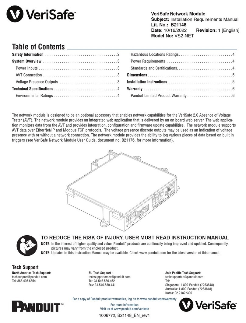
The network module is designed to be an optional accessory that enables network capabilities for the VeriSafe 2.0 Absence of Voltage
Tester (AVT). The network module provides an integrated web application that is delivered by an on board web server. The web applica-
tion monitors data from the AVT and provides integration, configuration and firmware update capabilities. The network module supports
AVT data over EtherNet/IP and Modbus TCP protocols. The voltage presence discrete outputs may be used as an indication of voltage
presence with or without a network connection. The network module provides the ability to log various pieces of data based on built in
triggers (see Data Logs Page for more information).
Before attempting to physically install the network module in hazardous or ordinary locations, refer to document no. B21148 (VeriSafe
Network Module Installation Requirements Manual) for physical installation requirements including; connectivity, ratings and environ-
mental specifications for the network module.

1006819, B21176_EN_rev3 2 06/19/2023
Web Application
FEATURES
The network module web application can be used to configure and monitor the AVT. Access the web
application by typing the network module IP address in a supported browser.
FIRST LOGIN
1. Type the network module IP address (default: 192.168.2.10) in a supported browser using HTTPS and not
HTTP.
Supported browsers: Chrome, Edge, Firefox
2. If the Browser displays “refused to connect” please double check that you are using “https://” protocol
and not “http://”
Figure 1. REFUSED CONNECTION EXAMPLE
3. By Default, the Web Interface uses a self-signed certificate. Until a CA signed certificate / key is installed,
browsers will display a security error. In Chrome browser, click advanced.
Figure 2. CERTIFICATE WARNING

06/19/2023 3 1006819, B21176_EN_rev3
4. Click on “Continue to 192.168.2.10 (unsafe)” and you will be prompted to the VeriSafe Network Module
web application page.
Figure 3. CONTINUE TO WEB APPLICATION LINK
5. On first login the user is required to change the admin password
Web App Login (factory default setting)
Username: admin
Password: admin
Figure 4. CHANGE PASSWORD
6. Before using the Network Module with an AVT unit, please ensure the firmware is updated to the latest
version by selecting the image below. This will take you to Panduit’s products software/firmware page
where the latest firmware version of the Network Module can be found.

1006819, B21176_EN_rev3 4 06/19/2023
WEB APPLICATION LAYOUT
The web application layout consists of a left sidebar menu and a content area loaded with content cards.
Figure 5. WEB APPLICATION DASHBOARD
Sidebar Menu
2nd Card
1st Card
LOGIN
On login the user will be
directed to the AVT Status
page.
AVT STATUS PAGE
After the user has logged in they will be redirected to the AVT Status page. This page consists of two data
cards with views that will be determined by the type of AVT in use and the user settings.
Figure 6. AVT STATUS PAGE 3-PHASE AVT (VS2-AVT-3P)

06/19/2023 5 1006819, B21176_EN_rev3
AVT STATUS PAGE FIRST CARD
Data presented in this card is updated as described in table 1. The user is presented with time stamps to
indicate when the data was last updated. Some data will not be shown until an absence of voltage test is
completed.
Figure 7. AVT STATUS PAGE 1ST CARD VIEWS
3-Phase View DC/Single-Phase View
Table 1.
1. Name User defined AVT name (Default blank). This is used to identify data log files
and appears in the side bar menu. Changes are automatically saved.
2. Date/Time Current Date/Time of the network module. Updated every 2 seconds.
3. Battery Voltage and
Test Temperature
Last measured value of the battery voltage and Internal temperature of the
AVT.
Updated when the user presses the test button and during the wakeup
cycle
Recommended to replace battery in the AVT when measured below 2.9V.
4. Connection Status Status of the connectivity between each pair of sensor leads based on the last
completed test performed when no voltage is present.
5. Test Result 1 Show the most recent test result from the AVT
Test Result 1 Date Date/Time of AVT test result 1
Test Result 2 Show the test result prior to test result 1
Test Result 2 Date Date/Time of AVT test result 2
6. AC/DC Selection
*(VS-AVT-1P Single phase(VS-AVT-1P Single phase
units only)units only)
Selects the appropriate power system. This will update the card view.
Changes are automatically saved.
7. Activate AVT Test
Button
Starts the absence of voltage test

1006819, B21176_EN_rev3 6 06/19/2023
AVT STATUS PAGE SECOND CARD
Data in this card is updated every 2 seconds. For single phase systems the view shown is determined by
selection on card 1 (table 1, item 6 AC/DC selection).
Figure 8. AVT STATUS PAGE SECOND CARD VIEWS
Three-Phase View Single-Phase View DC View
Table 2.
1. AVT Connection Status Indicates status of the connection between the isolation
module and network module. OK
DISCONNECTED
2. Voltage presence Reflects the status of the voltage presence indicators (Red LEDs) on the indicator
module
Reflects the status of the voltage presence contacts on the network module.
3. Voltage Measurements Measured peak voltage line
to ground
Calculated RMS and line to
line voltages
AC Range *Accuracy
0-33 VAC ± 7V
34-99 VAC ± 5V
100-300 VAC ± 2%
301-1000 VAC ± 1.5%
DC Range *Accuracy
0-100 VDC ± 5V
101-300 VDC ± 4%
301-700 VDC ± 2%
701-1000 VDC ± 1.5%
To get the most accurate voltage readings, ensure the
appropriate power system configuration is selected in the
web application.
*All values in this table are to be used as a reference and
are expected to be within these ranges.
Note: The absence of voltage indication from the AVT
utilizes a separate circuit that is optimized for the 3V
threshold.
4. AVT Temperature Represents the current temperature inside the AVT that is updated every 2 seconds.

06/19/2023 7 1006819, B21176_EN_rev3
DATA LOGS PAGE
This page allows the user to manage the log data stored on the network module SD card.
LOG TRIGGERS
Log entries are triggered by specific AVT events:
Change in state of any voltage presence indicator
Initiating the absence of voltage test
Daily AVT wakeup cycle
Figure 9. DATA LOGS PAGE DETAILS
Table 3.
1. Request Data Logs Request data log file from the network module
2. Download Logs (CSV) Download the data log file to local PC in CSV form
3. Download Filtered Logs (CSV) If filters are applied download the filtered data set only
4. Delete Logs Deletes all entries from the data log file
5. Filters Select filters. Use Update Filters and Clear Filters to manage
selections.
6. Log Items Data associated with each log entry.
NOTE: When log data is critical it is recommended the user periodically download the logs or to integrate the
system (EtherNet/IPTM or Modbus TCP) with an external data logging system.

1006819, B21176_EN_rev3 8 06/19/2023
SETTINGS PAGE
The settings page allows the user to configure and view the current state of the network module, retrieve AVT
information, check active faults, and update firmware.
Figure 10. SETTINGS PAGE

06/19/2023 9 1006819, B21176_EN_rev3
NETWORK MODULE SETTINGS
Figure 11. NETWORK MODULE SETTINGS CARD DETAILS
SAVE SETTINGS AND RESTART
Saves modified settings and restarts
the network module.
REFRESH
Replace all data in fields with the
last saved settings.
RESTART
Restart the network module without
saving changes to settings.
FACTORY RESET
Reset the network module to factory
default settings (see Table 4).
NOTE: If the web application is
unavailable, the network module can
be physically reset by depressing the
User Reset Button (refer to document
no. B21148 VeriSafe Network Module
Installation Requirements Manual
under the System Overview Section
for location on the Network Module).
Table 4.
1. Refresh Replace all data in fields with the last saved settings
2. Date & Time Displays current date and time associated with the network module.
3. Set Time Applies local web browser time to the network module.
4. Network Module FW Version Firmware version of the network module
5. Use NTP server Check to enable the use of NTP (Network Time Protocol)
6. NTP server address Enter server address to set time using NTP. Editable if Use NTP Server is checked.
7. Power System Configuration* Configuration of the power system that the AVT is monitoring. To report accurate voltage data,
the correct power system configuration must be selected. Default is Auto-Detect *
8. Modbus Enable or disable the Modbus TCP interface (default enabled)
9. EtherNet/IPTM Enable or disable the EtherNet/IPTM interface (default enabled)
10. DHCP Enable or disable DHCP (default disabled)
11. IP Address
Netmask
Gateway IP
DNS1
DNS2
Current IP address, Netmask and Gateway IP (read-only when DHCP is enabled)
DNS1 & DNS2 are always editable
Continued on next page

1006819, B21176_EN_rev3 10 06/19/2023
12. Web Server Mode The web server can be configured for either HTTP or HTTPS (default is HTTPS)
13. Download Certificate Download the network module certificate.
14. Upload PEM Certificate Upload a user supplied PEM certificate (default uses on board PEM certificate)
15. Upload PEM Private Key Upload a user supplied PEM private key (default uses on board PEM private key)
16. Use Custom Cert and Key Check to enable use of the user supplied certificate and private key for HTTPS. Disabled if
HTTPS is not selected for Web Server Mode.
17. Language Select desired language from the drop-down menu.
English, French, French (Canada), German, Italian, Korean, Spanish (Latin America), Chinese
18. Restart Restart the network module without saving changes to settings
19. Factory Reset Reset the network module to factory default settings
20. Save Settings and Restart Saves modified settings and restarts the network module.
*POWER SYSTEM CONFIGURATION
The AVT measures voltage between the sensor leads and ground leads and computes the associated phase-to-phase and RMS voltages.
The voltage measurements are then reported to the network module.
To report accurate voltage data, the appropriate power system configuration must be selected. The Standard selection (default) assumes
a wye or delta power system and is sufficient for most applications. If a special configuration (corner grounded delta, high-leg delta, and
single-phase 3-wire) is desired, select the appropriate application from the drop-down menu.

06/19/2023 11 1006819, B21176_EN_rev3
ABOUT AVT
Figure 12. ABOUT AVT CARD DETAILS
Displays firmware version, model number and universal identifier (UID) of the AVT. Use the refresh button to
update the card.
Refresh
AVT Data
ACTIVE FAULTS
Figure 13. ACTIVE FAULTS CARD DETAILS
This card will display active faults in the network module. The fault information is updated automatically every
3 seconds. See Troubleshooting for additional information.
Table 5.
1. Faults ID Description
0 Network Module Hardware Failure. Flash code 2 during boot up
1 Power from the network module to the AVT is over the limit.
2 Indicate the network module has been reset to factory defaults
3 Data received from AVT was unable to be processed
4 Timeout while communicating with AVT
5 General SD card error
6 SD card is full
7 Time has not updated
8 Time not set
9 Web server could not load custom certificate
2. Clear Faults The Clear Faults button allows the user to clear any faults on the network
module. If the fault condition is still present then the fault may be
presented after some time.

1006819, B21176_EN_rev3 12 06/19/2023
CHANGE PASSWORD
On initial login and factory reset the user will be prompted to change the password.
Figure 14.
UPDATE FIRMWARE
Download the latest firmware at www.panduit.com
Select Browse, navigate to the firmware file, and click the appropriate Update button.. The firmware update
process for both the network module and AVT should take approximately one minute.
Figure 15. UPDATE FIRMWARE CARD
AVT Firmware Update
During a firmware update communication between the
network module and the AVT will be temporarily lost. Upon
successful update use the About AVT card refresh button to
verify the firmware version matches what was downloaded.
Network Module Firmware Update
Upon successful firmware update the network module will
restart and you will be prompted to login.

06/19/2023 13 1006819, B21176_EN_rev3
DOCUMENTATION PAGE
This page provides the user with the information necessary to utilize the EtherNet/IPTM (EDS file download)
and Modbus TCP communications protocols. The web-application documentation page has the appropriate
EDS file readily available. For all other information regarding the communication protocols, please refer to
page 14 on this manual for the EtherNet/IPTM data model and page 19 for the Modbus TCP data model.
SUPPORT PAGE
Provides contact information and a link to the VeriSafe landing page on www.panduit.com
Queries the AVT and network module for product information to assist in technical support.
Contains a Licenses section outlining the Panduit License Agreement as well as the Web and System
licenses used in the creation of this product.
Figure 16. SUPPORT PAGE

1006819, B21176_EN_rev3 14 06/19/2023
Data Models
The following data models will describe the parameters utilized in the EtherNet/IPTM and Modbus TCP
communication protocols.
ETHERNET/IPTM DATA MODEL
Network Module Unit Object (100~Decimal, 64~Hex - 1 Instance)
All attribute IDs are in decimal value for each data item.
All attribute IDs are Instance 1 except for the revision item located in the first row of the table.
Item Name Description Value Type
(size bytes) Range
Revision (Instance 0)
Revision Number
Attribute ID: 1
Access Rule: Get
UINT(2) Data Value: 2
Battery Voltage
Last voltage reading of the AVT battery
(last test)
Attribute ID: 1
Access Rule: Get
REAL(4) 0.0 to 4.0 V
Date/Time
Current Date/Time set in the network
module
Attribute ID: 2
Access Rule: Get
ULINT(8) microseconds since epoch
Voltage Presence
Bit field status of the phase indicator
LEDs (red LEDs)
Attribute ID: 3
Access Rule: Get
WORD(2)
Bit Bit Name
0 Present L1 POS
1 Present L2 NEG
2 Present L3
0: Voltage not detected
1: Voltage detected
Connectivity Status
Connected status of each sensor lead L1,
L2, L3, PE Ground during last test.
Attribute ID: 4
Access Rule: Get
WORD(2)
Bit Bit Name
0 Connected L1
1 Connected L2
2 Connected L3
3 Connected PE GND
0: Sensor lead disconnected
1: Sensor lead connected
Continued on next page

06/19/2023 15 1006819, B21176_EN_rev3
Item Name Description Value Type
(size bytes) Range
Line to Ground
RMS Voltage
L1-G
L1 to Ground
Attribute ID: 5
Access Rule: Get
INT(2)
0 to 1100 VrmsL2-G
L2 to Ground
Attribute ID: 6
Access Rule: Get
L3-G
L3 to Ground
Attribute ID: 7
Access Rule: Get
Line to Ground
Peak Voltage
L1-G
L1 to Ground
Attribute ID: 8
Access Rule: Get
0 to 1500 VL2-G
L2 to Ground
Attribute ID: 9
Access Rule: Get
L3-G
L3 to Ground
Attribute ID: 10
Access Rule: Get
Line to Line
RMS Voltage
L1-L2
L1 to L2
Attribute ID: 11
Access Rule: Get
0 to 1100 Vrms
L1-L3
L1 to L3
Attribute ID: 12
Access Rule: Get
L2-L3
L2 to L3
Attribute ID: 13
Access Rule: Get
Line to Line
Peak Voltage
L1-L2
L1 to L2
Attribute ID: 14
Access Rule: Get
0 to 1500 VL1-L3
L1 to L3
Attribute ID: 15
Access Rule: Get
L2-L3
L2 to L3
Attribute ID: 16
Access Rule: Get
Test temperature
Temperature inside the AVT at the time of
the last AVT test (°C)
Attribute ID: 17
Access Rule: Get
-40°C to 85°C (-40°F to 185°F)
Disconnect state
[NOT IMPLEMENTED]
Disconnect phase open or closed
Attribute ID: 18
Access Rule: Get
WORD(2)
Bit Description
0 L1 open
1 L2 open
2 L3 open
0: Blade closed 1: Blade open
Continued on next page

1006819, B21176_EN_rev3 16 06/19/2023
Item Name Description Value Type
(size bytes) Range
Status
Status bits associated with the network
module and AVT
Attribute ID: 19
Access Rule: Get
DWORD(4)
Bit Bit Name
0Battery Warning
Indicator
0: Battery OK
1: Check battery
(low or not present)
1AVT
Temperature Fault
0: OK
1: Fault
2AVT
Power Source
0: Battery
1: Aux
3Phase Number
0: 3 Phase
1: Single phase
4User Threshold
Triggered
[NOT IMPLEMENTED]
0: Not triggered
1: Triggered
If any user defined
threshold is triggered
this bit will go to active
(1)
5Disconnect Module
Present
[NOT IMPLEMENTED]
0: No
1: Yes
6AVT
Internal Fault
0: OK
1: Fault
7Network
Module Fault
0: OK
1: Fault
Continued on next page

06/19/2023 17 1006819, B21176_EN_rev3
Item Name Description Value Type
(size bytes) Range
AVT Result 1
Most recent test result of an AVT test
Attribute ID: 20
Access Rule: Get
WORD(2)
Bit Result
0Passed
0F
1Battery Voltage Low
1F
2Voltage Exceeded
2F
3Temperature not in
range
3F
4Connectivity not
Confirmed
4F
5Diagnostic 5
5F
6Diagnostic 6
6F
7Diagnostic 7
7F
8Diagnostic 8
8
#F indicates the number of flashes that will
be seen on the AVT indicator module for
this error code
0: false
1: true
Continued on next page

1006819, B21176_EN_rev3 18 06/19/2023
Item Name Description Value Type
(size bytes) Range
AVT Result 2
Second most recent test result of an AVT
test
Attribute ID: 21
Access Rule: Get
WORD(2)
Bit Result
0Passed
0F
1Battery Voltage Low
1F
2Voltage Exceeded
2F
3Temperature not in
range
3F
4Connectivity not
Confirmed
4F
5Diagnostic 5
5F
6Diagnostic 6
6F
7Diagnostic 7
7F
8Diagnostic 8
8
#F indicates the number of flashes that will
be seen on the AVT indicator module for
this error code
0: false
1: true
AVT Result 1 Date/Time
Date/Time of AVT result 1
Attribute ID: 22
Access Rule: Get
ULINT(8)
Microseconds since epoch
AVT Result 2 Date/Time
Date/Time of AVT result 2
Attribute ID: 23
Access Rule: Get
ULINT(8)
Microseconds since epoch
Current Temperature
Current Temperature inside the AVT (°C)
Attribute ID: 24
Access Rule: Get
INT(2)
-40°C to 85°C (-40°F to 185°F)
Activate AVT Test
Starts the absence of voltage test
Attribute ID: 25
Access Rule: Get/Set
DINT(4)
0: Test not activated
1: Test activated

06/19/2023 19 1006819, B21176_EN_rev3
MODBUS TCP DATA MODEL
INPUT DATA
All values are contained in input registers (offset 30000).
Input Data Item Description Value Type
(size bytes) Range
Date/Time
Current Date/Time set in the network
module
Start Address: 1
End Address: 4
uint64_t(8) Microseconds since epoch
Battery Voltage
Last voltage reading of the AVT battery
(last test)
Start Address: 5
End Address: 6
float(4)
0.0 to 4.0 V
Voltage Presence
Bit field status of the phase indicator
LEDs (red LEDs)
Start Address: 7
End Address: 7
uint16_t(2)
Bit Bit Name
0 Present L1 POS
1 Present L2 NEG
2 Present L3
0: Voltage not detected
1: Voltage detected
Connectivity Status
Connected status of each sensor lead L1,
L2, L3, PE Ground during last test.
Start Address: 8
End Address: 8
uint16_t(2)
Bit Bit Name
0 Connected L1
1 Connected L2
2 Connected L3
3 Connected PE GND
0: Sensor lead disconnected
1: Sensor lead connected
Continued on next page

1006819, B21176_EN_rev3 20 06/19/2023
Input Data Item Description Value Type
(size bytes) Range
Line to Ground
RMS Voltage
L1-G
L1 to Ground
Start Address: 9
End Address: 9
int16_t(2)
0 to 1100 VrmsL2-G
L2 to Ground
Start Address: 10
End Address: 10
L3-G
L3 to Ground
Start Address: 11
End Address: 11
Line to Ground
Peak Voltage
L1-G
L1 to Ground
Start Address: 12
End Address: 12
0 to 1500 VL2-G
L2 to Ground
Start Address: 13
End Address: 13
L3-G
L3 to Ground
Start Address: 14
End Address: 14
Line to Line
RMS Voltage
L1-L2
L1 to L2
Start Address: 15
End Address: 15
0 to 1100 Vrms
L1-L3
L1 to L3
Start Address: 16
End Address: 16
L2-L3
L2 to L3
Start Address: 17
End Address: 17
Line to Line
Peak Voltage
L1-L2
L1 to L2
Start Address: 18
End Address: 18
0 to 1500 VL1-L3
L1 to L3
Start Address: 19
End Address: 19
L2-L3
L2 to L3
Start Address: 20
End Address: 20
Test temperature
Temperature inside the AVT at the time of
the last AVT test (°C)
Start Address: 21
End Address: 21
-40°C to 85°C (-40°F to 185°F)
Disconnect state
[NOT IMPLEMENTED]
Disconnect phase open or closed
Start Address: 22
End Address: 22
uint16_t(2)
Bit Description
0 L1 open
1 L2 open
2 L3 open
0: Blade Closed 1: Blade Opened
Continued on next page
Other manuals for VeriSafe VS2-NET
2
Table of contents
Other Panduit Control Unit manuals

Panduit
Panduit IndustrialNet IAEBHUSBAA User manual

Panduit
Panduit VeriSafe VS2-NET User manual

Panduit
Panduit MA002 User manual

Panduit
Panduit smartzone G5 User manual

Panduit
Panduit TX6 PLUS User manual

Panduit
Panduit CJ6X88TG Series User manual

Panduit
Panduit TX6 PLUS User manual

Panduit
Panduit CJSK6X88TG Series User manual

Panduit
Panduit RFM-470 User manual

Panduit
Panduit CJRR Series User manual