manuals.online logo
Brands
  1. Home
  2. •
  3. Brands
  4. •
  5. Panduit
  6. •
  7. Media Converter
  8. •
  9. Panduit Atlona OmniStream AT-OMNI-512 User manual

Panduit Atlona OmniStream AT-OMNI-512 User manual

Atlona Manuals
Networked AV
AT-OMNI-512
Dual-Channel Networked AV Encoder
OmniStream™R-Type
AT-OMNI-512 2
Version Information
Version Release Date Notes
10 May 2023 Documentation typos corrected.
AT-OMNI-512 3
Sales, Marketing, and Customer Support
Operating Notes
IMPORTANT: Visit http://www.atlona.com/product/AT-OMNI-512 for the latest rmware
updates and User Manual.
Warranty
To view the product warranty, use the following link or QR code:
https://atlona.com/warranty/.
Main Oce
Atlona Incorporated
70 Daggett Drive
San Jose, CA 95134
United States
Oce: +1.408.962.0515
Sales and Customer Service Hours
Monday - Friday: 6:00 a.m. - 4:30 p.m. (PST)
https://atlona.com/
International Headquarters
Atlona International AG
Tdistrasse 18
8002 Zrich
Switzerland
Oce: +41.43.508.4321
Sales and Customer Service Hours
Monday - Friday: 09:00 - 17:00 (UTC +1)
AT-OMNI-512 4
1. Read these instructions.
2. Keep these instructions.
3. Heed all warnings.
4. Follow all instructions.
5. Do not use this product near water.
6. Clean only with a dry cloth.
7. Do not block any ventilation openings. Install in
accordance with the manufacturer’s instructions.
8. Do not install or place this product near any heat
sources such as radiators, heat registers, stoves, or
other apparatus (including ampliers) that produce
heat.
9. Do not defeat the safety purpose of a polarized
or grounding-type plug. A polarized plug has two
blades with one wider than the other. A grounding
type plug has two blades and a third grounding
prong. The wide blade or the third prong are
provided for your safety. If the provided plug does
not t into your outlet, consult an electrician for
replacement of the obsolete outlet.
10. Protect the power cord from being walked on
or pinched particularly at plugs, convenience
receptacles, and the point where they exit from the
product.
11. Only use attachments/accessories specied by
Atlona.
12. To reduce the risk of electric shock and/or damage
to this product, never handle or touch this unit or
power cord if your hands are wet or damp. Do not
expose this product to rain or moisture.
13. Unplug this product during lightning storms or when
unused for long periods of time.
14. Refer all servicing to qualied service personnel.
Servicing is required when the product has been
damaged in any way, such as power-supply cord or
plug is damaged, liquid has been spilled or objects
have fallen into the product, the product has been
exposed to rain or moisture, does not operate
normally, or has been dropped.
CAUTION: TO REDUCT THE RISK OF
ELECTRIC SHOCK
DO NOT OPEN ENCLOSURE OR EXPOSE
TO RAIN OR MOISTURE.
NO USER-SERVICEABLE PARTS
INSIDE REFER SERVICING TO
QUALIFIED SERVICE PERSONNEL.
CAUTION
RISK OF ELECTRIC SHOCK
DO NOT OPEN
The exclamation point within an equilateral triangle is intended to alert the user to
the presence of important operating and maintenance instructions in the literature
accompanying the product.
The information bubble is intended to alert the user to helpful or optional opera-
tional instructions in the literature accompanying the product.
Important Safety Information
FCC Compliance
Copyright, Trademark, and Registration
FCC Compliance and Advisory Statement: This hardware device complies with Part 15 of the FCC rules. Operation is subject to the following two
conditions: 1) this device may not cause harmful interference, and 2) this device must accept any interference received including interference that
may cause undesired operation. This equipment has been tested and found to comply with the limits for a Class A digital device, pursuant to Part
15 of the FCC Rules. These limits are designed to provide reasonable protection against harmful interference in a commercial installation. This
equipment generates, uses, and can radiate radio frequency energy and, if not installed or used in accordance with the instructions, may cause
harmful interference to radio communications. However there is no guarantee that interference will not occur in a particular installation. If this
equipment does cause harmful interference to radio or television reception, which can be determined by turning the equipment o and on, the user
is encouraged to try to correct the interference by one or more of the following measures: 1) reorient or relocate the receiving antenna; 2) increase
the separation between the equipment and the receiver; 3) connect the equipment to an outlet on a circuit dierent from that to which the receiver
is connected; 4) consult the dealer or an experienced radio/TV technician for help. Any changes or modications not expressly approved by the
party responsible for compliance could void the user’s authority to operate the equipment. Where shielded interface cables have been provided
with the product or specied additional components or accessories elsewhere dened to be used with the installation of the product, they must be
used in order to ensure compliance with FCC regulations.
© 2023 Atlona Inc. All rights reserved. “Atlona” and the Atlona logo are registered trademarks of Atlona Inc. Pricing, specications and availability
subject to change without notice. Actual products, product images, and online product images may vary from images shown here.
Dolby, Dolby Atmos, and the double-D symbol are registered trademarks of Dolby Laboratories Licensing Corporation.
The terms HDMI, HDMI High-Denition Multimedia Interface, and the HDMI Logo are trademarks or registered trademarks of
HDMI licensing Administrator, Inc.
For DTS patents, see http://patents.dts.com. Manufactured under license from DTS, Inc. DTS, the Symbol, DTS and the Symbol together, and
Digital Surround are registered trademarks and/or trademarks of DTS, Inc. in the United States and/or other countries. © DTS, Inc. All Rights
Reserved.
All other trademark(s), copyright(s), and registered technologies mentioned in this document are the properties of their respective owner(s).
AT-OMNI-512 5
Introduction 7
Features 7
Package Contents 7
Introduction to OmniStream 8
OmniStream 101 8
IP Address Assignment 8
Network Bandwidth and OmniStream Compression 9
Streams 9
Sessions 9
Subscribing to a Stream 10
OmniStream Naming Schema 11
Panel Description 12
Installation 13
RS-232 Connections 13
IR Connections 14
Connection Instructions 15
Connection Diagram 16
Getting Started 17
Rebooting OmniStream 17
ID Button 17
Broadcast Messaging 17
Resetting to Factory-Defaults 18
Using the ID button 18
Using the Mclear command 18
Using the Web Server 18
LED Indicators 19
Accessing the Web Server 20
Basic Conguration Tutorial 21
Physical Connections 21
Setting the System Mode 22
Conguring Inputs 23
Encoder Settings 25
Creating a Session 26
Subscribing to an Encoder 28
Video Conguration 28
Audio Conguration 29
Conguring the HDMI Output Stream 30
Troubleshooting 33
Encoder Checklist 33
Decoder Checklist 34
Table of Contents
AT-OMNI-512 6
Table of Contents
Device Operation 35
EDID Management 35
Selecting an EDID Preset 35
Adding a Custom EDID 36
Device Control 37
Downstream Control using RS-232 37
Control using TCP Proxy 40
Downstream Control using Triggering 42
Upstream Control using RS-232 47
Upstream Control using IR 49
AES67 Audio 50
Scrambling 53
Slate / Logo Insertion 54
Adding Slates / Logos 54
Deleting Slates 55
Deleting Logos 55
Text Insertion 56
Conguring a Static IP Address 57
Conguration and Management Interfaces 58
Web Server 58
System information page 58
SAP Listener page 61
Input page 62
EDID page 65
Encoding page 66
Serial page 68
Session page 70
Logo page 74
Text page 76
Network page 78
PTP page 80
LLDP page 82
Conguration page 83
Users page 84
License page 85
Upgrade page 86
Appendix 87
Updating the Firmware 87
Performing a Link Test 88
Mounting Instructions 91
Rack Tray for OmniStream 92
Specications 93
AT-OMNI-512 7
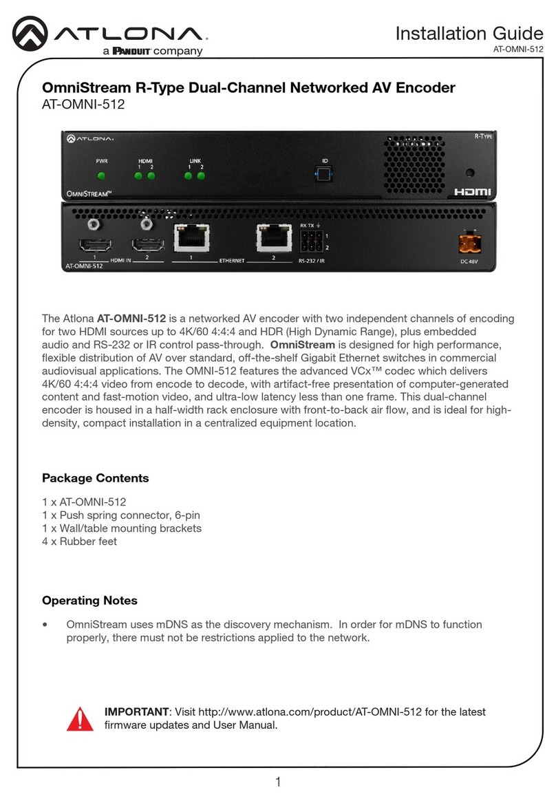
The Atlona AT-OMNI-512 is a networked AV encoder with two independent channels of encoding for two HDMI
sources up to 4K/60 4:4:4 and HDR (High Dynamic Range), plus embedded audio and RS-232 or IR control pass-
through. OmniStream is designed for high performance, exible distribution of AV over standard, o-the-shelf
Gigabit Ethernet switches in commercial audiovisual applications. The OMNI-512 features the advanced VCx™
codec which delivers 4K/60 4:4:4 video from encode to decode, with artifact-free presentation of computer-
generated content and fast-motion video, and ultra-low latency less than one frame. This dual-channel encoder is
housed in a half-width rack enclosure with front-to-back air ow, and is ideal for high-density, compact installation in
a centralized equipment location.
Introduction
Features
Package Contents
1 x AT-OMNI-512
1 x 6-pin push-spring connector
2 x Wall/table mounting brackets
4 x Rubber feet
• Best-in-class AV over IP performance and reliability
over Gigabit Ethernet.
• AV encoder for HDMI up to 4K/UHD, plus embedded
audio and RS-232 or IR control pass-through.
• Dual-channel AV encoding.
• Supports 4K/60 4:4:4 plus HDR formats.
• Advanced VCx codec.
• High-eciency coding.
• HDCP compliance.
• Ultra-fast switching between 4K/60 video streams.*
• Integrated Ethernet link testing.
• Thumbnail preview of encoded video streams.
• Simplify integration with plug-and-play network
switch compatibility.
• Local or PoE (Power over Ethernet) powering.
• Secure content distribution with AES-128 encryption.
• Supports industry-standard, network security
features and protocols.
• AES67-compatible.
• Simultaneous OmniStream and AES67 audio
streaming.
• Enhance AV presentations with visual enhancements.
• EDID management.
• Audio processing and pass-through.
• System management.
• Compact enclosure.
* Logo / image display features and 1080i video are not supported.
AT-OMNI-512 8
OmniStream 101
AT-OMNI-512
AT-OMNI-121
PoE Network Switch
Ethernet Ethernet
LAN
TM
O
MNI
S
TREAM
LINKPWR
R
-
T
YPE
ID
HDMI
PWR LINK
TM
O
MNI
S
TREAM
ID
1 2 1 2
R
-
T
YPE
Decoder IP Address: 192.168.1.38
Encoder IP Address: 192.168.1.27
Introduction to OmniStream
OmniStream products are similar in principle to matrix switch endpoints: A/V signals are sent from one point
(transmitter) to another point (receiver) over category cable. However, OmniStream stands apart from matrix
switchers, in that it is an IP-based solution, allowing this data to be sent over a standard IP network. In addition,
these endpoints are referred to as encoders and decoders. Encoders act as “transmitters” and decoders act as
“receivers”.
IP Address Assignment
Figure 1.1 below, shows an encoder and a decoder, connected through a network switch. As with all network
devices, both the encoder and decoder must have unique IP addresses. OmniStream encoders and decoders are
DHCP-enabled, by default. This means that when the encoder/decoder is connected to the network, and a DHCP
server is available, the encoder/decoder will automatically be assigned an IP address. If no DHCP server is available,
then the unit will use a self-assigned IP address within the range of 169.254.xxx.xxx/16. OmniStream devices
can also be assigned a static IP address, if necessary. Static IP addressing will be covered in a later section.
Figure 1.1 - An encoder and decoder on a network, with assigned IP addresses.
DEFINITIONS
Encoder – Compresses source signals before sending them out over a network environment.
Decoder – Receives and decompresses signals from an encoder and sends them to an output
device, such as a display or other sink device.
IP Address – A unique numerical label that is assigned to each device connected to a network.
AT-OMNI-512 9
Figure 1.2 - Video and audio streams contained within a session.
UDP PortMulticast IP AddressVideo Stream
UDP PortMulticast IP AddressAudio Stream
Session
Introduction to OmniStream
Network Bandwidth and OmniStream Compression
When sending video and audio over a network, the available bandwidth needs to be managed. Gigabit Ethernet
switches are very common and can take advantage of installed Category 5e cable. 10-Gigabit Ethernet switches
are available, but are more expensive per port and require Category 6A cable or better. The chart below shows
uncompressed data rates for common resolutions. These data rates exceed the available bandwidth of Gigabit
Ethernet, but using the compression technology in OmniStream, this video can be streamed over cost-eective
Gigabit networks.
Resolution Data Rate*
1920 x 1080p 30 Hz 2.2 Gbps
1920 x 1080p 60 Hz 4.5 Gbps
3840 x 2160p 30 Hz 8.9 Gbps
3840 x 2160p 60 Hz 17.8 Gbps
OmniStream compresses the source data at the encoder, before it is sent out over the network. This process is
known as encoding. OmniStream uses VCx and VC-2 compression, which are intermediate compression schemes
and oer lower latency and higher video delity than an interframe compression scheme, such as H.264 or H.265.
Interframe codecs are typically used by cable or internet providers and use very aggressive bit rates (low bandwidth)
with high latency (delay), which results in lag. VCx and VC-2 provide both high quality (high bit rates) and very low-
latency for a much more desirable viewing experience.
* Data rate is shown without compression.
Streams
Sessions
The term stream is used throughout this manual, to describe the dierent types of signals that are transmitted over a
network. For example, if a blu-ray player is connected to an encoder, both video and audio are sent to the encoder
over an HDMI cable. The term video stream is used to identify the video portion of a signal and audio stream
identies the audio portion of the signal.
A session is a way of organizing audio and video streams. The session identies each stream with a unique multicast
IP address and UDP port assignment. This provides an address to determine where the package of audio and video
should be sent. Table 1.1 illustrates how a session encapsulates a video and audio stream.
NOTE: Sessions are not limited to only video and audio streams. Control data, such as IR and
RS-232, as well as AES67 audio, can also be contained within a session. These topics will be
covered in a later chapter.
AT-OMNI-512 10
Introduction to OmniStream
HDMI
PWR LINK
TM
O
MNI
S
TREAM
ID
1 2 1 2
R
-
T
YPE
TM
O
MNI
S
TREAM
LINKPWR
R
-
T
YPE
ID
HDMI
PWR LINK
TM
O
MNI
S
TREAM
ID
1 2 1 2
R
-
T
YPE
AT-OMNI-512
AT-OMNI-121
PoE Network Switch
Ethernet
Stream
Ethernet
AT-OMNI-512
Stream
Ethernet
AB
C
Encoder IP Address: 192.168.1.27
Multicast IP Address (Video): 226.0.0.1
UDP Port (Video): 1000
Multicast IP Address (Audio): 226.0.10.1
UDP Port (Audio): 1100
Decoder IP Address: 192.168.1.38
Multicast IP Address (Video): 226.0.0.1
UDP Port (Video): 1000
Multicast IP Address (Audio): 226.0.10.1
UDP Port (Audio): 1100
Encoder IP Address: 192.168.1.98
Multicast IP Address (Video): 226.0.0.2
UDP Port (Video): 1000
Multicast IP Address (Audio): 226.0.10.2
UDP Port (Audio): 1100
Subscribing to a Stream
To receive information from an encoder, the decoder must subscribe to the multicast IP address and UDP port of
the stream(s). Note that the decoder does not subscribe to the session, but to the stream(s) within the session.
The process of subscribing is similar to changing the channel on a Set-Top Box. For example, in order to view the
content on channel 213, the Set-Top Box must be set to channel 213. Similarly, for a decoder to subscribe to an
encoder stream, the multicast IP address and UDP port settings on the decoder must be set to the same values as
the encoder to which it is subscribed. Note that the management IP address of a unit is dierent than its multicast IP
address.
Figure 1.3 shows two encoders and a single decoder connected to a network switch. Decoder “C” is subscribed to
encoder “A”, since the multicast IP addresses and UDP port numbers for both video and audio are set to the same
values as encoder “A”.
Figure 1.2 - Diagram of a video and audio stream, transmitted over an Ethernet cable, to the subscribing decoder.
Video Data
Audio Stream
Video Stream Multicast IP: 226.0.0.1
Multicast IP: 226.0.10.1
UDP Port: 1000
UDP Port: 1100
Ethernet
Encoder
Video
Destination Multicast/Unicast Address
226.0.0.1
Destination UDP Port
1000
Audio
Destination Multicast/Unicast Address
226.0.10.1
Destination UDP Port
1100
Decoder
Video
Subscribed Multicast Address
226.0.0.1
Port
1000
Audio
Subscribed Multicast Address
226.0.10.1
Port
1100
Figure 1.3 - Decoder “C” subscribed to encoder “A”.
AT-OMNI-512 11
Introduction to OmniStream
DEFINITIONS
Stream – Describes the video, audio, or any data that is transmitted from an encoder over the
network.
Multicast IP Address – A class-D IP address assigned to a stream.
UDP Port – User Datagram Protocol (UDP) port. Part of the network addressing scheme to send
and receive data to the proper destination on a network.
Subscribing – The process of selecting the multicast IP address to “listen to”, in order to receive
one or more encoder streams at the decoder endpoint.
OmniStream Naming Schema
Each OmniStream model has a dierent set of inputs and outputs and, depending upon the number of inputs and
outputs. The number of supported session will depend upon the encoder model.
The last three numbers of the OmniStream SKU, describe the model version, model type, and number of inputs/
outputs. The number of Ethernet ports and HDMI ports will be the same.
For example, the numbering scheme on the AT-OMNI-112 is read as follows:
• AT-OMNI-112 1= OmniStream Pro (“R-Type” models begin with the number “5”).
1 = Indicates that the device is an encoder (decoders are identied with the number “2”).
2 = The number of sources (encoder)/sinks (decoder).
Encoders Description
AT-OMNI-111
AT-OMNI-111-WP
• One HDMI input
• One Ethernet output
• Supports up to six sessions
AT-OMNI-112 • Two HDMI inputs
• Two Ethernet outputs
• Supports up to six sessions
AT-OMNI-512 • Two HDMI inputs
• Two Ethernet outputs
• Supports up to four sessions
Decoders Description
AT-OMNI-121 • One HDMI output
• One Ethernet input
AT-OMNI-122 • Two HDMI outputs
• Two Ethernet inputs
AT-OMNI-512 12
HDMI
PWR LINK
TM
OMNISTREAM
ID
1 2 1 2
R-TYPE
AT-OMNI-512
ETHERNET
RS-232 / IR
DC 48V
RX TX
1
2
HDMI IN
2
121
HDMI
PWR LINK
TM
OMNISTREAM
ID
1 2 1 2
R-TYPE
AT-OMNI-512
ETHERNET
RS-232 / IR
DC 48V
RX TX
1
2
HDMI IN
2
121
Front
Rear
1 2 3
86 7 9
54
Panel Description
1 PWR
This LED indicator is green when the unit is powered
and booted.
2 HDMI 1 / HDMI 2
These LED indicators are green when the link
between source and encoder is good.
3 LINK 1 / LINK 2
These LED indicators will be green when the link
integrity between the between the encoder and the
network switch is good.
4 ID
Press this button to send a broadcast message to
any network devices that are listening. This button
is also used to set the encoder to factory-default
settings. Refer to ID Button (page 17) for more
information.
5 Reboot button
Press this button, using a small, pointed object to
reboot the unit.
6 HDMI IN 1 / HDMI IN 2
Connect HDMI cables from these ports to a UHD/HD
source.
7 ETHERNET 1 / ETHERNET 2
Connect Ethernet cables from these ports to the
Local Area Network (LAN).
8 RS-232 / IR
Connect the included 6-pin push-spring block to
connect an automation system and an IR emitter or
extender. RS-232 Connections (page 13) and IR
Connections (page 14) for more information.
9 DC 48V
Connect the optional 48V DC power supply to
this receptacle. This power supply is available,
separately, and can be purchased through Atlona.
NOTE: Some older hardware
revisions do not have an ID button.
AT-OMNI-512 13
Installation
The AT-OMNI-512 provides RS-232 over IP which allows communication between an automation system and an RS-
232 device. This step is optional. Either the top three or bottom three set of terminals can be used for RS-232.
1. Use wire strippers to remove a portion of the cable jacket.
2. Remove at least 3/16” (5 mm) from the insulation of the RX, TX, and GND wires.
3. Insert the TX, RX, and GND wires into correct terminal on the included push-spring connector. If using non-
tinned stranded wire, press the orange tab, above the terminal, while inserting the exposed wire. Repeat this
step for the TX, RX, and GND connections.
Push tab
to unlock GND
RX
TX
RS-232 Connections
NOTE: Typical DB9 connectors use pin 2 for TX, pin 3 for RX, and pin 5 for ground. On some
devices, pins 2 and 3 are reversed.
AT-OMNI-512 14
Installation
The same port that provides RS-232 connections also supports bidirectional IR pass-through, allowing a device to
be controlled from either the headend or the decoder endpoint. This step is optional. Either the top three or bottom
three set of terminals can be used for IR. Only the RS-232 2 port (bottom set of connectors) supports both RS-232
and IR. Therefore, this port must be used for IR connections.
IR emitter conguration
IR extender conguration
GND (black)
IR emitter
SIGNAL (white/black)
RX TX GND
GND (black)
SIGNAL (white/black)
Control
Unit
TX out
GND
RX TX GND
IR Connections
Push tab
to unlock
AT-OMNI-512 15
Connection Instructions
Installation
1. Connect an Ethernet cable from the ETHERNET 1 and ETHERNET 2 ports on the encoder to a PoE-capable
switch on the Local Area Network (LAN). Note that if a PoE-capable switch is not available, the 48V DC power
supply (sold separately) must be connected to the encoder.
2. Connect an HDMI cable from each source to the HDMI ports on the encoder.
3. RS-232 (optional)
Refer to RS-232 Connections (page 13) for wiring information.
• Connect the RS-232 controller/automation system to the RS-232 port on the encoder.
• Connect the RS-232 device to the RS-232 port on the decoder.
4. IR (optional)
Refer to IR Connections (page 14) for wiring information.
• IR emitter
Connect the IR emitter to the TX and GND pins of the RS-232 2 port. The IR emitter must be placed no
more than one inch from the IR sensor on the device, in order to function properly.
• IR extender
Connect the IR extender from the RX and GND pins of the RS-232 2 port to the associated pins on the
control system.
5. Once power is applied, the PWR indicator, on the front panel, will turn red, then amber, then green.
IMPORTANT: If a PoE-capable switch is not available, then the 48V DC power supply (sold
separately) must be connected to the encoder.
HDMI
PWR LINK
TM
O
MNI
S
TREAM
ID
1 2 1 2
R
-
T
YPE
AT-OMNI-512
ETHERNET
RS-232 / IR
DC 48V
RX TX
1
2
HDMI IN
2
121
PWR indicator
AT-OMNI-512 16
Connection Diagram
Installation
AT-OMNI-121
Ethernet
Ethernet
PoE Network Switch
Ethernet
LAN
HDMI
HDMI
Display
TM
O
MNI
S
TREAM
LINKPWR
ID
Source
AT-OMNI-512
HDMI
PWR LINK
TM
O
MNI
S
TREAM
ID
1 2 1 2
R
-
T
YPE
AT-OMNI-512 17
Getting Started
HDMI
PWR LINK
TM
O
MNI
S
TREAM
ID
1 2 1 2
R
-
T
YPE
AT-OMNI-512
ETHERNET
RS-232 / IR
DC 48V
RX TX
1
2
HDMI IN
2
121
To reboot the OmniStream encoder, press and release the recessed button, on the far-right side of the unit, using a
small, pointed object. Rebooting the encoder does not reset the encoder to factory-default settings.
Rebooting OmniStream
HDMI
PWR LINK
TM
O
MNI
S
TREAM
ID
1 2 1 2
R
-
T
YPE
AT-OMNI-512
ETHERNET
RS-232 / IR
DC 48V
RX TX
1
2
HDMI IN
2
121
The ID button serves two functions:
1. Sends a broadcast message over the network to any devices that may be listening.
2. Resets the encoder to factory-default settings.
ID Button
Press and release the ID button to send a broadcast notication over the network to any devices that may be
listening.
Broadcast Messaging
NOTE: Some older hardware revisions do not have an ID button.
AT-OMNI-512 18
Getting Started
1. Press and hold the ID button for approximately 30 seconds.
2. The LED indicators on the front panel will ash, then turn “o.”
3. The encoder is now reset and will need to be recongured.
1. Connect a PC to serial port 1 using a USB to serial cable.
2. Set the PC console port to the following settings: 9600 baud, 8 data bits, 1 stop bit, no parity.
3. Once connected to the CLI, execute the Mclear command.
1. Log in to the encoder using the built-in web server. Refer to ##accessingwebserver for more information.
Note that OmniStream devices communicate using both LLDP and CDP protocols. Consult the switch
documentation for information on returning neighbor details from the CLI. Neighbor details will include the IP
address of the encoder.
2. Click the FACTORY RESET button.
3. The encoder is now reset and will need to be recongured.
Using the ID button
Using the Mclear command
Using the Web Server
WARNING: Performing a factory-default reset will erase all user-programmed settings from the
encoder. IP settings are not preserved.
Resetting to Factory-Defaults
AT-OMNI-512 19
LED Indicators
The following table provides a listing of front-panel LED indicators and their status:
Getting Started
LED Description
PWR Off • If using a PoE switch, make sure that the port on the switch that is
connected to the encoder, has PoE enabled. When the encoder is
powered using PoE, the PWR indicator will be green.
• Check the Ethernet cable for possible damage or loose connections.
• Connect the optional 48V DC power supply (available from atlona.
com) to the encoder. When using an external power supply, the PWR
indicator will be green.
Red • The encoder is booting.
Amber • The encoder is booting and/or attempting to locate a DHCP server.
Green • The encoder is ready.
HDMI 1 / 2 Red • No source is connected to the input.
• Check the HDMI cable for possible damage or loose connections.
Green • The link integrity between the source and the encoder is good.
LINK 1 / 2 Red • The optional 48V DC power supply is connected, but no Ethernet
cables are connected between the switch and the ETHERNET port(s).
• Check the Ethernet cable for possible damage or loose connections.
Amber • The encoder is booting.
Green • Link integrity is good between the encoder and the network.
AT-OMNI-512 20
Getting Started
Accessing the Web Server
In order to access the web server of the desired encoder/decoder, the IP address of the encoder must be known.
This can be accomplished by using any of the following methods: 1) Running IP scanner software or 2) accessing
the encoder using the domain name. When running an IP scanner, both the computer and the OmniStream
encoders/decoders must be connected to the same network.
TIP: Atlona recommends downloading and using the Network Assignment Planner, when
setting up OmniStream products on the network. Recording this information in this document
will provide a “snapshot” of the current OmniStream network conguration. The Network
Assignment Planner is available for download on the OmniStream product pages, under the
Resources tab.
1. Launch the desired web browser and enter the IP address or domain name of the encoder in the address bar.
2. Enter the username and password. Note that the password eld will always be masked. The default credentials
are:
Username: admin
Password: Atlona
3. The System Information page will be displayed.

Other manuals for Atlona OmniStream AT-OMNI-512

2

This manual suits for next models

6

Other Panduit Media Converter manuals

Panduit Atlona OmniStream AT-OMNI-512 User manual

Panduit

Panduit Atlona OmniStream AT-OMNI-512 User manual

Panduit SmartZone PViQ Use and care manual

Panduit

Panduit SmartZone PViQ Use and care manual

Panduit Atlona OmniStream 122 User manual

Panduit

Panduit Atlona OmniStream 122 User manual

Panduit Atlona OmniStream AT-OMNI-512 User manual

Panduit

Panduit Atlona OmniStream AT-OMNI-512 User manual

Panduit Atlona AT-OME-RX31 User manual

Panduit

Panduit Atlona AT-OME-RX31 User manual

Panduit Atlona Omega AT-OME-SR21 User manual

Panduit

Panduit Atlona Omega AT-OME-SR21 User manual

Panduit Atlona AT-HD-SC-500 User manual

Panduit

Panduit Atlona AT-HD-SC-500 User manual

Panduit Atlona OmniStream 111 User manual

Panduit

Panduit Atlona OmniStream 111 User manual

Panduit Atlona OmniStream R-Type Guide

Panduit

Panduit Atlona OmniStream R-Type Guide

Panduit Atlona OmniStream AT-OMNI-112 User manual

Panduit

Panduit Atlona OmniStream AT-OMNI-112 User manual

Panduit Atlona OmniStream AT-OMNI-521 User manual

Panduit

Panduit Atlona OmniStream AT-OMNI-521 User manual

Panduit Atlona OmniStream AT-OMNI-311 User manual

Panduit

Panduit Atlona OmniStream AT-OMNI-311 User manual

Panduit Atlona OmniStream AT-OMNI-111 User manual

Panduit

Panduit Atlona OmniStream AT-OMNI-111 User manual

Panduit Atlona Omega AT-OME-SR21 User manual

Panduit

Panduit Atlona Omega AT-OME-SR21 User manual

Panduit Atlona OmniStream AT-OMNI-121 User manual

Panduit

Panduit Atlona OmniStream AT-OMNI-121 User manual

Panduit ATLONA OmniStream 101 User manual

Panduit

Panduit ATLONA OmniStream 101 User manual

Panduit Atlona AT-HDR-M2C Technical manual

Panduit

Panduit Atlona AT-HDR-M2C Technical manual

Panduit AT-OMNI-111-WP User manual

Panduit

Panduit AT-OMNI-111-WP User manual

Panduit ATLONA AT-VCC-IR3 User manual

Panduit

Panduit ATLONA AT-VCC-IR3 User manual

Panduit ATLONA AT-HDVS-150-RX User manual

Panduit

Panduit ATLONA AT-HDVS-150-RX User manual

Panduit Atlona AT-VCC-RS232-KIT User manual

Panduit

Panduit Atlona AT-VCC-RS232-KIT User manual

Panduit ATLONA  OmniStream 111 WP User manual

Panduit

Panduit ATLONA OmniStream 111 WP User manual

Panduit AT-OMNI-111-WP User manual

Panduit

Panduit AT-OMNI-111-WP User manual

Panduit Atlona Omega AT-OME-RX21 User manual

Panduit

Panduit Atlona Omega AT-OME-RX21 User manual

Popular Media Converter manuals by other brands

Baumer HOG 220 Mounting and operating instructions

Baumer

Baumer HOG 220 Mounting and operating instructions

Kramer VP-425 user manual

Kramer

Kramer VP-425 user manual

GRASS VALLEY ADVC3000 - datasheet

GRASS VALLEY

GRASS VALLEY ADVC3000 - datasheet

ACTi V31 Quick installation guide

ACTi

ACTi V31 Quick installation guide

PAC LOC PRO ADVANCED LPA-1.2 quick start guide

PAC

PAC LOC PRO ADVANCED LPA-1.2 quick start guide

Lika ROTAPULS CK46 Series manual

Lika

Lika ROTAPULS CK46 Series manual

Marmitek Split TS14 user manual

Marmitek

Marmitek Split TS14 user manual

KBC ENC-H-W Series quick start guide

KBC

KBC ENC-H-W Series quick start guide

SKYDANCE D4-L quick start guide

SKYDANCE

SKYDANCE D4-L quick start guide

Analog Devices LTC7810ELXE Demo Manual

Analog Devices

Analog Devices LTC7810ELXE Demo Manual

Analytic Systems VTC1015 Series Installation & operation manual

Analytic Systems

Analytic Systems VTC1015 Series Installation & operation manual

AV TOOL AVT-3190HD instruction manual

AV TOOL

AV TOOL AVT-3190HD instruction manual

Parker TWIN-N Series user manual

Parker

Parker TWIN-N Series user manual

Transition Networks SBFTF1011-140 user guide

Transition Networks

Transition Networks SBFTF1011-140 user guide

Philips SM40 Instructions for use

Philips

Philips SM40 Instructions for use

LINK-MI LM-YH02 operating instructions

LINK-MI

LINK-MI LM-YH02 operating instructions

ADF Web HD67E09-A1 user manual

ADF Web

ADF Web HD67E09-A1 user manual

Sentient N11CX user manual

Sentient

Sentient N11CX user manual

manuals.online logo
manuals.online logoBrands
  • About & Mission
  • Contact us
  • Privacy Policy
  • Terms and Conditions

Copyright 2025 Manuals.Online. All Rights Reserved.