manuals.online logo
Brands
  1. Home
  2. •
  3. Brands
  4. •
  5. SKYDANCE
  6. •
  7. Media Converter
  8. •
  9. SKYDANCE D4-L User manual

SKYDANCE D4-L User manual

Dimension
Technical Parameters
Summary
● Input voltage: 12-24VDC
● Output type: PWM constant voltage
● Output current: 4CH, 5A/CH
● Output power: 4 x (60-120)W
● Decode number: 1/2/4 DMX Channel
● Dimming range: 0-100%
● Working temperature: -30℃~55℃
● Product size: L170×W50×H23mm
● Packing size: L172×W53×H27(mm)
● Net weight: 130g
170mm
50mm 23mm
4CH 12-24V 5A Constant Voltage
DMX512 & RDM Decoder
Interface Specification
Power input+
Common +
Power input -
Output channel 3
Output channel 2
Output channel 1
Output channel 4
Common +
Common +
Common +
Power Supply
12-24VDC
Constant Voltage N
AC110-230V
Wiring diagram
+
R
G
B
W
RGBW LED strip
Uin=12-24VDC
Iin=20.5A
Uout=4×(12-24)VDC
Iout=4×5A
Pout=4×(60-120)W
Temp Range:
-30℃~+55℃
D4-LDMX512 & RDM Decoder
DMX I N/OUT
D+ D- D+ D-
Uin=12-24VDC
Iin=20.5A
Uout=4×(12-24)VDC
Iout=4×5A
Pout=4×(60-120)W
Temp Range:
-30℃~+55℃
D4-LDMX51 2 & RDM Dec oder
DMX I N/OUT
D+ D- D+ D-
DMX D+output
DMX D- input -
DMX D+ input
DMX D- output
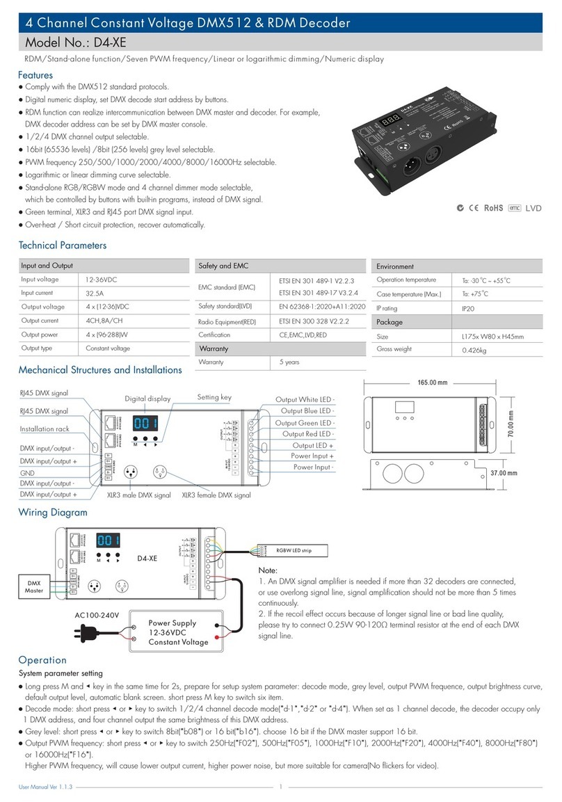
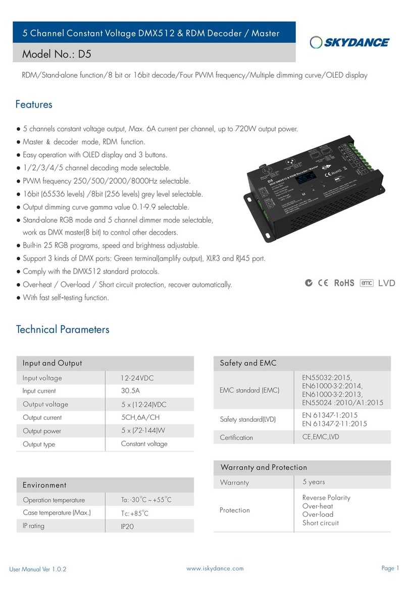
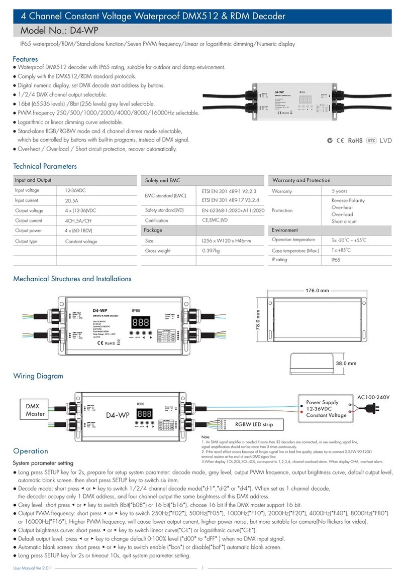
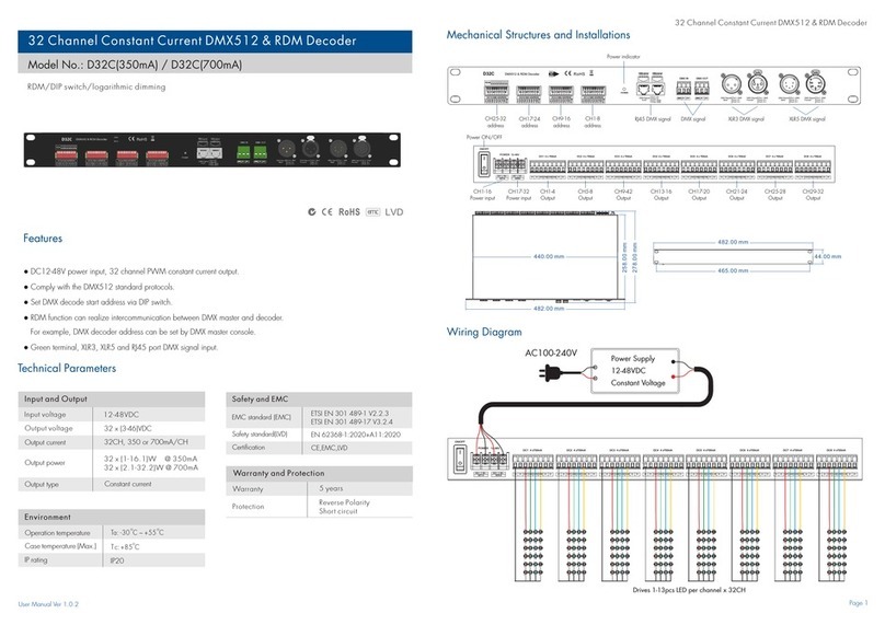
● DMX512 & RDM decoder, four channel constant voltage output, 5A per channel.
● Comply with the latest DMX512, DMX512(1990), DMX512-A, RDM V1.0 (E1.20 - 2006 ESTA Standard)
standard protocols.
● RDM bi-directional communication function, can realize intercommunication between DMX master
and decoder. for example, you can set DMX decoder address by DMX master console.
● DMX address can be set easily and shown on the digital numeric display.
● Compatial with our DMX masters such as T12,T13,T15,T16,T17, and any other high quality
DMX master.
● It can also work as stand-alone RGB/RGBW controller, have 30 kinds dynamic mode,
adjustable speed and brightness.
● It can also work as stand-alone 4 channel dimming controller, each channel adjust
brightness independently, and save up to 8 groups brightness.
● Work with power repeater to expand output unlimitedly.
● Short press M key, when display 001~999, enter DMX mode.
● Press ◀ or ▶ key to change DMX decode address(001~999),
long press for fast adjustment.
● Long press M and ◀ key for 2s, prepare for setup system parameter: decode mode,
output PWM frequence, output brightness cur ve, automatic blank screen.
short press M key to switch four item.
● Decode mode: short press ◀ or ▶ key to switch one-channel decode("d-1"),
two-channel decode("d-2") and four-channel decode("d-4").
● Output PWM frequence: short press ◀ or ▶ key to switch 500Hz("F-L") or 2KHz("F-H").
● Output brightness curve: short press ◀ or ▶ key to switch linear curve("C-L") or
logarithmic cur ve("C-E").
● Automatic blank screen: short press ◀ or ▶ key to switch enable ("bon") or disable("boF")
automatic blank screen.
● Long press M key for 2s or timeout 10s, quit system parameter setting.
DMX mode
(001~999)
Key Function
DMX mode
System parameter setting
DMX Master
12-24VDC
Stand-alone RGB/RGBW mode
No. Name
P01
P02
P03
P04
P05
P06
P07
P08
P09
P10
Static red
Static green
Static blue
Static yellow
Static cyan
Static purple
Static white
RGB jump
7 color jump
Red strobe
Warranty Agreement
1. 5-year warranty:
● The warranty is for free repair or replacement and covers manufacturing faults only.
● Do not include fees of on site maintenance and consumable parts.
2. Limited Warranty
● Artificial damage caused by improper use, such as use inappropriate power supply, improper
accessories, improper installation, did not follow the instructions, error using or negligence.
● Any damages caused by force majeure, such as natural disaster, abnormal voltage.
● The normal use of products caused by aging, wear and tear, but it does not affect the normal use.
Malfunctions analysis & troubleshooting
Safety & Warnings
Malfunctions
Causes Troubleshooting
Uneven intensity
between front and
rear,with voltage
drop
1. Output cable is too long.
2. Wire diameter is too small.
3. Overload beyond power supply
capability.
4. Overload beyond controller
capability.
1. Reduce cable or loop supply.
2. Change wider wire.
3. Replace higher power supply.
4. Add power repeater.
1. No power.
2. Wrong connection or insecure.
1. Check the power.
2. Check the connection.
No light
1. Set corrrect decode address.
Wrong color 1. DMX decode address error.
RGB change mode list
No. Name No. Name
P11
P12
P13
P14
P15
P16
P17
P18
P19
P20
P21
P22
P23
P24
P25
P26
P27
P28
P29
P30
Green strobe
Blue strobe
White strobe
RGB strobe
7 color strobe
Red fade in and out
Green fade in and out
Blue fade in and out
White fade in and out
RGBW fade in and out
Red yellow smooth
Green cyan smooth
Blue purple smooth
Blue white smooth
RGB+W smooth
RGBW smooth
RGBY smooth
Yellow cyan purple smooth
RGB smooth
6 color smooth
● Short press M key, when display P01~P30,
enter stand-alone RGB/RGBW mode.
● Press ◀ or ▶ key to change dynamic mode
number(P01~P30).
● Each mode can adjust speed and brightness.
Long press M key for 2s, prepare for setup mode speed, brightness,
W channel brightness.
Short press M key to switch three item.
Press ◀ or ▶ key to setup value of each item.
Mode speed : 1-10 level speed(S-1, S-9, S-F).
Mode brightness: 1-10 level brightness(b-1, b-9, b-F).
W channel brightness: 0-255 level brightness(400-4FF).
Long press M key for 2s, or timeout 10s, quit setting.
Speed
(8 level)
Brightness
(10 level,100%)
Restore factory default parameter
● Long press ◀ and ▶ key for 2s, restore factory default parameter, display"RES".
● Factory default parameter: DMX decode mode, DMX first address is 1, four channel decode,
high PWM frequence output, logarithmic brightness curve, RGB mode number is 1,
dimmer mode number is 1, disable automatic blank screen.
1. The product shall be installed and serviced by a qualified person.
2. This product is non-waterproof. Please avoid the sun and rain.
3. Good heat dissipation will prolong the working life of the controller. Please ensure good
ventilation.
4. Please check if the output voltage of any power supplies used complywith the working voltage
of the product.
5. Ensure all wire connections and polarities are correct and secure before applying power to avoid
any damages to the LED lights.
6. If a fault occurs please return the product to your supplier. Do not attempt to fix this product by
yourself.
Stand-alone dimmer mode
● Short press M key, when display L-1~L-8, enter stand-alone dimmer mode.
● Press ◀ or ▶ key to change dimmer mode number(L-1~L-8).
● Each dimmer mode can adjust each channel brightness independently.
Long press M key for 2s, prepare for setup four channel brightness.
Short press M key to switch four channel.
Press ◀ or ▶ key to setup brightness value of each channel.
Long press M key for 2s, or timeout 10s, quit setting.
● Another way to setup channel brightness: Enter DMX mode,
long press M key for 2s will save current decode value.
Stand-alone dimmer mode
(L-1~L-8)
(P01~P30)
Other SKYDANCE Media Converter manuals

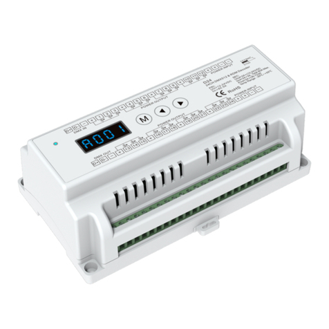
SKYDANCE D24 User manual

SKYDANCE

SKYDANCE D24 User manual

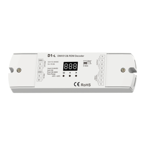
SKYDANCE D1-L User manual

SKYDANCE

SKYDANCE D1-L User manual

SKYDANCE D4-XE User manual

SKYDANCE

SKYDANCE D4-XE User manual

SKYDANCE D5 User manual

SKYDANCE

SKYDANCE D5 User manual

SKYDANCE D4-WP User manual

SKYDANCE

SKYDANCE D4-WP User manual

SKYDANCE D32C User manual

SKYDANCE

SKYDANCE D32C User manual

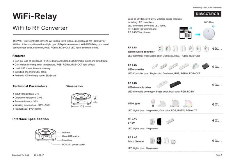
SKYDANCE WiFi-Relay User manual

SKYDANCE

SKYDANCE WiFi-Relay User manual

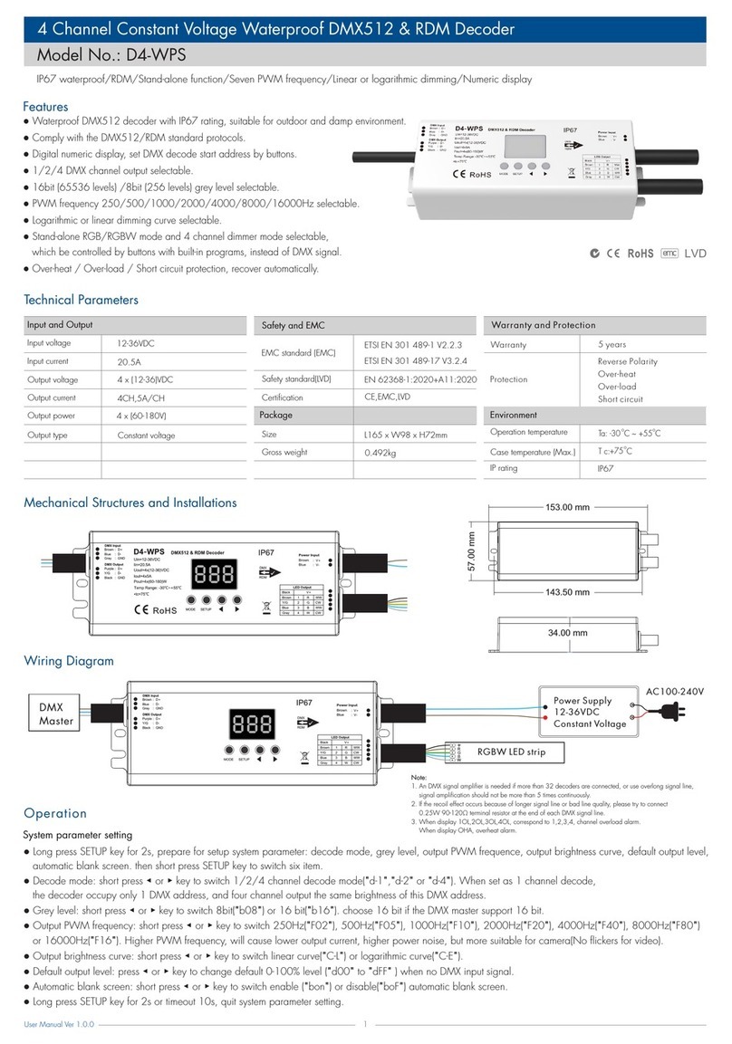
SKYDANCE D4-WPS User manual

SKYDANCE

SKYDANCE D4-WPS User manual

SKYDANCE D4-WP User manual

SKYDANCE

SKYDANCE D4-WP User manual

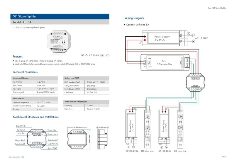
SKYDANCE SA User manual

SKYDANCE

SKYDANCE SA User manual

SKYDANCE D4-P User manual

SKYDANCE

SKYDANCE D4-P User manual

SKYDANCE D12A User manual

SKYDANCE

SKYDANCE D12A User manual

SKYDANCE D1-L User manual

SKYDANCE

SKYDANCE D1-L User manual

SKYDANCE D4-P User manual

SKYDANCE

SKYDANCE D4-P User manual

SKYDANCE SA User manual

SKYDANCE

SKYDANCE SA User manual

Popular Media Converter manuals by other brands

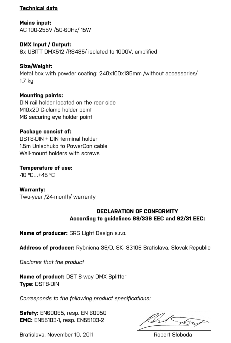
SRS Light Design DST8-DIN Series instruction manual

SRS Light Design

SRS Light Design DST8-DIN Series instruction manual

Allied Telesis AT-MMC6005 installation guide

Allied Telesis

Allied Telesis AT-MMC6005 installation guide

Teradek Vidiu X reference guide

Teradek

Teradek Vidiu X reference guide

DirectOut Technologies MADI.9648 user manual

DirectOut Technologies

DirectOut Technologies MADI.9648 user manual

VideoLogix Proteus-IV user manual

VideoLogix

VideoLogix Proteus-IV user manual

Fujitsu UTY-VMSX installation manual

Fujitsu

Fujitsu UTY-VMSX installation manual

Williams AV WaveCAST quick start guide

Williams AV

Williams AV WaveCAST quick start guide

Converters.TV 967 Operation manual

Converters.TV

Converters.TV 967 Operation manual

Aerotech MXH Series Hardware manual

Aerotech

Aerotech MXH Series Hardware manual

Antrica ANT-36000 quick start guide

Antrica

Antrica ANT-36000 quick start guide

infobit iTrans DX-TR-22 quick guide

infobit

infobit iTrans DX-TR-22 quick guide

Dawson DZA50 user manual

Dawson

Dawson DZA50 user manual

Solidyne ADA102 owner's manual

Solidyne

Solidyne ADA102 owner's manual

Samar cdm-600 Operation manual

Samar

Samar cdm-600 Operation manual

exemys EGW1-IA3-MB user manual

exemys

exemys EGW1-IA3-MB user manual

Texas Instruments PCM2704 manual

Texas Instruments

Texas Instruments PCM2704 manual

ADF Web HD67428 user manual

ADF Web

ADF Web HD67428 user manual

Kramer VP-505 user manual

Kramer

Kramer VP-505 user manual

manuals.online logo
manuals.online logoBrands
  • About & Mission
  • Contact us
  • Privacy Policy
  • Terms and Conditions

Copyright 2025 Manuals.Online. All Rights Reserved.