INSTALLATION INSTRUCTIONS CM361C
For Technical Support: www.panduit.com/resources/install_maintain.asp
Patch Cord Management
Page 7 of 8
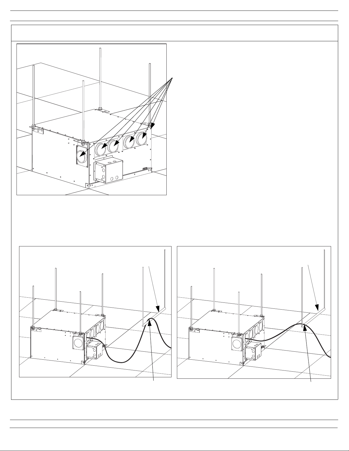
Step 2
Plug in a 3’ (1m) patch cord into a port on
the switch. Route patch cord up and into the
integrated horizontal slack manager. Create
a loop in the patch cord (opposite direction
of step 1) and bring forward. Plug other end
of the patch cord into the desired jack in the
patch panel.
Repeat the process for each bay of ports on
the switch. Use Tak Ties to secure cables to
sheer forms located on the horizontal slack
manager.
Step 3
Plug in a 3’ (1m) patch cord into a port on
the switch. Route patch cord up and into the
integrated horizontal slack manager. Create
a loop in the patch cord and bring forward.
Plug other end of the patch cord into the
desired jack in the patch panel.
Repeat the process for each bay of ports on
the switch. Use Tak Ties to secure cables to
sheer forms located on the horizontal slack
manager.
Second bay of ports (12) on the switch
Third bay of ports (12) on the switch
Fourth bay of ports (12) on the switch
Step 4
Plug in a 3’ (1m) patch cord into a port on
the switch. Route patch cord up and into the
integrated horizontal slack manager. Create
a loop in the patch cord (opposite direction
of step 3) and bring forward. Plug other end
of the patch cord into the desired jack in the
patch panel.
Repeat the process for each bay of ports on
the switch. Use Tak Ties to secure cables to
sheer forms located on the horizontal slack
manager.