Installation Guide
AT-VTP-550
6
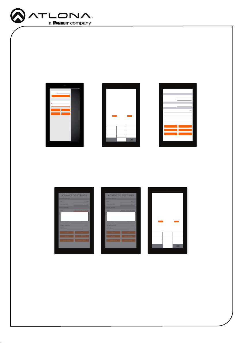
Set Configuration PIN
ABC DEF
GHI JKL MNO
PQRS TUV WXYZ
1 2
(Note: Once a pin is set, it will be required to edit settings going
forward)
(Enter a blank pin to remove)
3
4 5 6
7 8
0
9
CANCEL SAVE PIN
ADVANCED SETTINGS
Set Static IP
IP Address
Subnet Mask
Default Gateway
DNS Server 75.75.75.75
10.0.0.1
255.255.255.0
10.0.0.123
URL
Gateway Settings
Device Settings
Touch Screen LAN Configuration
0.0.0.0
Alternate URL 0.0.0.0
Alias Velocity Touch Panel 800
SAVE
FACTORYRESET
CLEAR CACHE
SCAN NETWORK
CANCEL
SET PIN
Cache has been successfully cleared. Press
OK to restart.
OK
ADVANCED SETTINGS
Set Static IP
IP Address
Subnet Mask
Default Gateway
DNS Server 75.75.75.75
10.0.0.1
255.255.255.0
10.0.0.123
URL
Gateway Settings
Device Settings
Touch Screen LAN Configuration
0.0.0.0
Alternate URL 0.0.0.0
Alias Velocity Touch Panel 800
SAVE
FACTORYRESET
CLEAR CACHE
SCAN NETWORK
CANCEL
SET PIN
Changing advanced settings requires
application restart.
OK
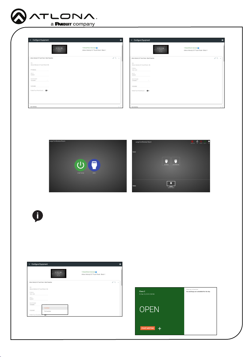
Device Settings - The touch pad can be renamed for easier syncing with Velocity. Type the
name into the Alias eld.
Touch Screen LAN Conguration - The current IP settings will display in these elds. To
switch to a static IP, select the Set Static IP slider, ll in the IP information, and press Save.
Set PIN - The default PIN of 554361 can be changed to a new pin by pressing the Set PIN
button. Type the new PIN in and press Save PIN.
Clear Cache - Press the Clear Cache button to release the current cache of the VTP. Press
the OK button to verify.
Factory Reset - Press the Factory Reset button to clear all the settings and start the touch
pad set up again. Press the OK button to verify.
Advanced Settings
Verify your PIN
554361
ABC DEF
GHI JKL MNO
PQRS TUV WXYZ
1 2 3
4 5 6
7 8
0
9
CANCEL VERIFY
URL
GATEWAY SETTINGS
TOUCH SCREEN SETTINGS
System Volume
Screen Brightness
0.0.0.0
REFRESH PAGE
CLEAN SCREEN CLOSE
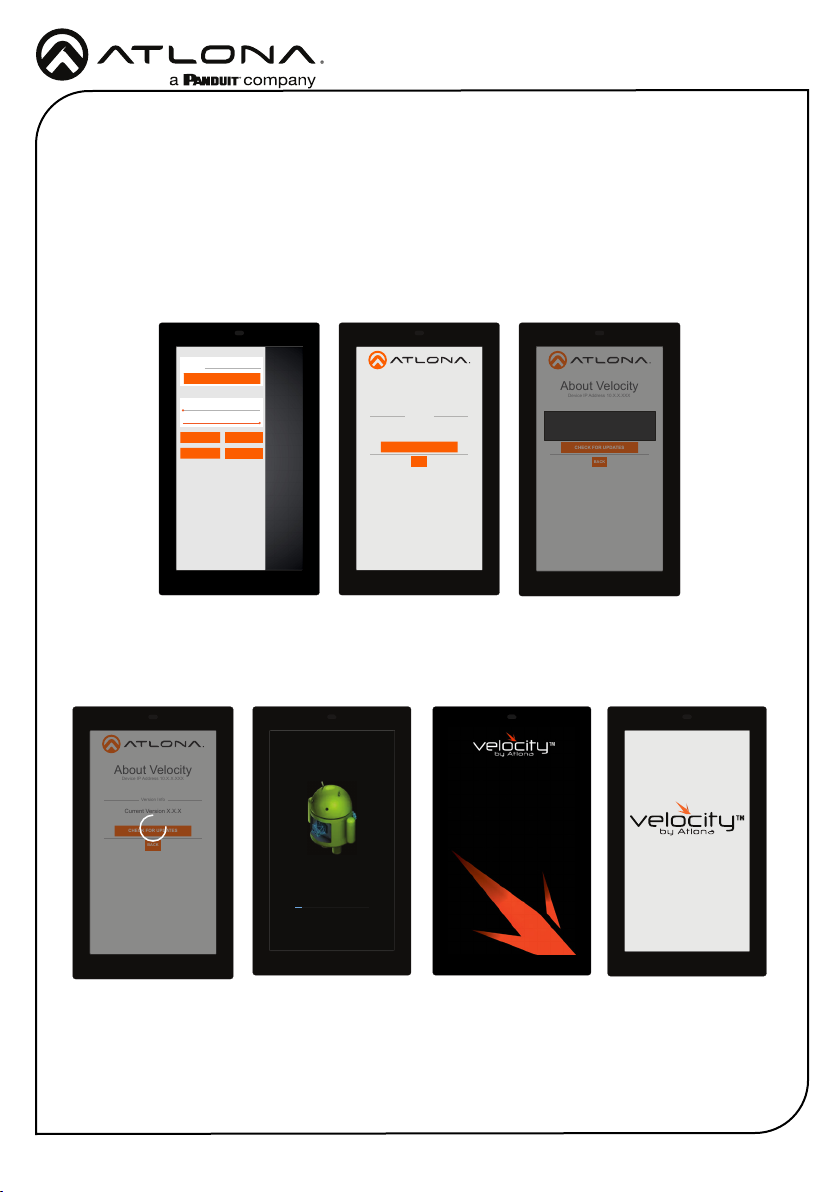
ABOUT VELOCITY ADVANCED SETUP
Once the touch pad has been set up, the settings can be changed or reset only through the
advanced settings.
1 To access the settings, swipe from the left side of the touch pad to the right.
2 Select Advanced Setup.
3 Type in the PIN. Default PIN is 554361.
ADVANCED SETTINGS
Set Static IP
IP Address
Subnet Mask
Default Gateway
DNS Server 75.75.75.75
10.0.0.1
255.255.255.0
10.0.0.123
URL
Gateway Settings
Device Settings
Touch Screen LAN Configuration
0.0.0.0
Alternate URL 0.0.0.0
Alias Velocity Touch Panel 550
SAVE
FACTORYRESET
CLEAR CACHE
SCAN NETWORK
CANCEL
SET PIN
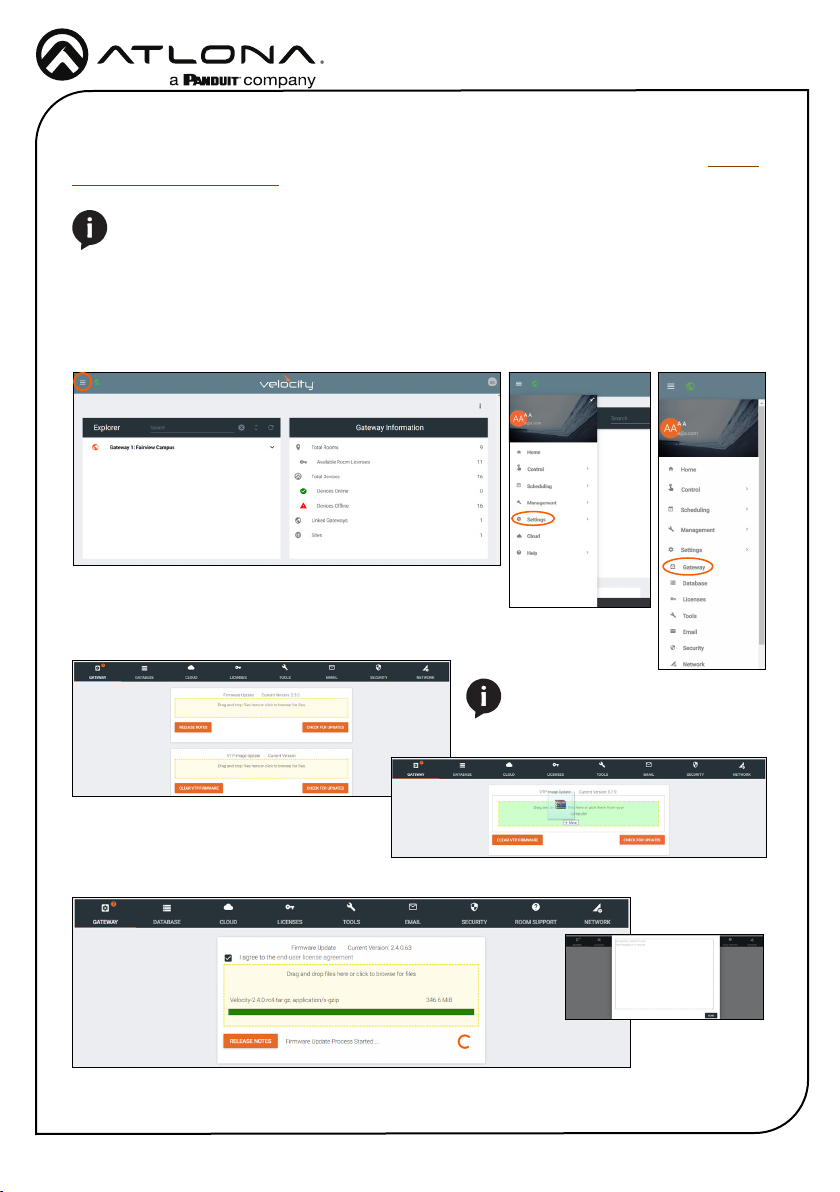
Within the advanced settings, all the touch pad settings can be changed or reset.
Gateway Settings -
a If the gateway IP is known, it can be typed into the URL eld.
b If the gateway IP is unknown, press the Scan Network button to search for and add
the gateway.