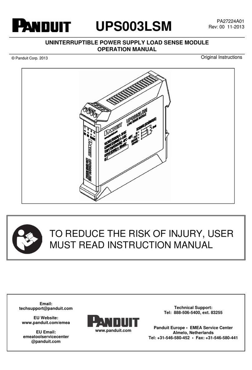
Panduit UPS003LSM User manual

UPS003LSM
PA27224A01
Rev: 023-2014
UNINTERRUPTIBLE POWER SUPPLY LOAD SENSE MODULE
OPERATION MANUAL
© Panduit Corp. 2014
Original Instructions
TO REDUCE THE RISK OF INJURY, USER
MUST READ INSTRUCTION MANUAL
Email:
techsupport@panduit.com
EU Website:
www.panduit.com/emea
EU Email:
emeatoolservicecenter
@panduit.com
www.panduit.com
Technical Support:
Tel: 1-888-506-5400, ext. 83255
Panduit Europe • EMEA Service Center
Almelo, Netherlands
Tel: +31-546-580-452 • Fax: +31-546-580-441

©Panduit Corp. 2014 OPERATION MANUAL UPS003LSM
Page: 1 of 7
TABLE OF CONTENTS
UPS LSM GENERAL SPECIFICATIONS ............................................................................2
Model Number ...............................................................................2
Input Power....................................................................................2
Output Power.................................................................................2
Environmental ...............................................................................2
Compliance....................................................................................2
Installation.....................................................................................2
Performance ..................................................................................3
PRECAUTIONS AND GENERAL GUIDELINES..................................................................3
Safety Warnings............................................................................3
Electrical Safety Practices......................................................4
Personal Safety.......................................................................4
Service.....................................................................................5
1. INTRODUCTION..............................................................................................................5
1.1. BACKGROUND......................................................................5
1.2. PURPOSE...............................................................................5
1.3. TERMS AND ABBREVIATIONS ............................................5
1.4. INSTALLATION......................................................................6
TABLE OF FIGURES
Figure 1: DIN Rail Installation..................................................................................................... 6
Figure 2: System Block Diagram ................................................................................................ 6
Figure 3: Load Sense Module..................................................................................................... 7
NOTE: Throughtout this document the UPS003LSM (Uninterruptible Power
Supply Load Sense Module) may also be referred to as “UPS LSM”.

©Panduit Corp. 2014 OPERATION MANUAL UPS003LSM
Page: 2 of 7
UPS LSM GENERAL SPECIFICATIONS
Model Number
UPS003LSM
Input Power
Voltage: 30.0 VDC MAX
Current: 5 A MAX
Output Power
Voltage: 30.0 VDC MAX
Sense: 100 mV MAX
Current: 5 A MAX
Environmental
Operating Temperature: -40 to +60°C.
Storage (non-operational) Temperature: -40 to +70°C.
Humidity: 0 to 95% RH, noncondensing
Operational Vibration: 2G at 10 to 500 Hz
Operational Shock: 20G (11ms 3 bumps / direction, 18 bumps in total)
Compliance
o UL 1778 and CSA C22.2 No. 107.3-05 “Uninterruptible Power Supply Equipment”
o UL 508 and CSA-C22.2 No. 14 “Industrial Control Equipment”
o UL 60950-1, 2nd ed, 2011-12-19, CSA C22.2 No. 60950-1-07, 2nd ed, 2011-12
"Information Technology Equipment - Safety - Part 1: General Requirements"
o (Low-Voltage Directive*) IEC 60950-1:2005+AM 2009, EN 60950-
1:2006+A1:2010+A11:2009+A12:2011 "Information Technology Equipment -
Safety - Part 1: General Requirements"
o ISA 12.12.01:2013, CSA C22.2 No. 213-1987M (R2013) “Standard For Nonincendive Electrical
Equipment for Use in Class I and II, Division 2 and Class III, Divisions 1 and 2 Hazardous (Classified)
Locations”
o FCC Title 47 CFR 15 Subpart B Emissions Class A
o
RoHS Allmaterials and componentsused must meet the material restrictionsof European Directive
2002/95/EC on the Restriction of Hazardous Substances
o CAN ICES-3(A)/NMB-3(A), ICES-003 Issue 5
o IP20 per IEC 60529
o IEC Ex (pending)
Model No. / QC #
Voltage / Current / Temp /
Output
Conformances
Approvals
Installation
Top hat (DIN) rail EN 50022
Width: 22.6mm (0.89 in)
Depth: 113.3mm (4.46 in)

©Panduit Corp. 2014 OPERATION MANUAL UPS003LSM
Page: 3 of 7
Height: 111.5mm (4.39 in)
Weight: 105.7g max (0.233 lbs, max.)
Terminals: screw type, accepts #12 to #18 AWG, stranded/solid/terminated
The device shall have control wiring along the top edge.
Performance
Voltage Drop: 100 mV maximum at 5 A
PRECAUTIONS AND GENERAL GUIDELINES
The basic condition for safe use and proper operation of the UPS LSM is the knowledge and attention
to the safety information provided in this manual.
The following safety information must be observed by all persons who will work with the UPS LSM.
All rules and instructions for the work place must be observed, especially those for prevention of
accidents.
This symbol is used to call your attention to hazards or unsafe practices which could
result in an injury or property damage. The signal word, defined below, indicates the
severity of the hazard. The message after the signal word provides information for
preventing or avoiding the hazard.
WARNING Hazards which, if not avoided, COULD result in severe injury or death.
CAUTION Hazards or unsafe practices which, if not avoided, MAY result in injury or
property damage.
Safety Warnings
WARNING
•Read all safety warning and all instructions. Failure to follow the warnings
and instructions may result in electric shock, fire and/or serious injury.
•Save all warnings and instructions for future reference.
Panduit Corp. recommends the UPS LSM be used with all installed safety features. Customer
assumes all liability for injury that could result from improper use of this UPS LSM and
responsibility for all necessary training to ensure safe operation of this UPS LSM.
•FOR INSTALLATION AND USE BY TRAINED PERSONNEL ONLY.
•IF ANY DAMAGE TO THE PRODUCT IS APPARENT OR SUSPECTED, DO NOT USE THE
PRODUCT. REFER PRODUCT TO QUALIFIED SERVICE PERSONNEL.
•FCC WARNING: CHANGES OR MODIFICATIONS TO THE PRODUCT COULD VOID THE
USER’S AUTHORITY TO OPERATE THE PRODUCT.
•USE RECOMMENDED ACCESSORIES. CONSULT THE OWNER’S MANUAL FOR
RECOMMENDED ACCESSORIES. THE USE OF IMPROPER ACCESSORIES MAY CAUSE
RISK OF INJURY TO PERSONS.

©Panduit Corp. 2014 OPERATION MANUAL UPS003LSM
Page: 4 of 7
Electrical Safety Practices
GROUNDING:
In the event of a malfunction or breakdown, grounding provides a path of least resistance for
electric current which reduces the risk of electrical shock.
Improper connection of the equipment grounding conductor can result in a risk of
electric shock. The conductor with insulation having an outer surface that is green
with or without yellow stripes is the equipment-grounding conductor.
Check with a qualified electrician, or service personnel if the grounding instructions
are not completely understood; or if in doubt as to whether the UPS LSM is properly
grounded.
Avoid body contact with earthed or grounded surfaces, such as pipes, radiators,
ranges and refrigerators.
There is an increased risk of electric shock if your body is earthed or grounded.
WARNING
ONLY OPERATE THE UPS LSM IN A CLEAN, DRY, INDOOR ENVIRONMENT.
DO NOT EXPOSE THE UPS LSM TO RAIN OR WET CONDITIONS.
Water entering a UPS LSM will increase the risk of electric shock.
KEEP AWAY FROM LIVE CIRCUITS:
•Operating personnel must not remove covers.
•Replacement of components and internal adjustments must be made by qualified
maintenance personnel.
•Disconnect power when replacing components.
•Dangerous voltages may exist even with the power removed.
•To avoid injuries, always disconnect power and turn power switch to OFF.
•Input connection to the product must remain accessible as a disconnect device.
•DO NOT work on the product; connect or disconnect cables during periods of
lightning.
•Provide wiring per national and local electrical codes.
Warning: A disconnect switch shall be provided by others for DC input
circuit and shall be in accordance with the National Electric Code, ANSI/NFPA 70.
Personal Safety
WARNING
Use personal protective equipment. Safety glasses must be worn at all times by all
persons installing the UPS LSM.

©Panduit Corp. 2014 OPERATION MANUAL UPS003LSM
Page: 5 of 7
Service
•Have your UPS LSM serviced by a qualified repair person using only identical
replacement parts.
Contact Panduit Tool Service at the following locations:
Panduit Tool Solutions Division (USA)
16530 W. 163rd Street
Lockport, IL 60441
Tel.: 1-888-506-5400, ext. 83255
Panduit EMEA Service Center (EUR)
EMEA Tool Service Center
Bedrijvenpark Twente 360
7602 KL Almelo
tel + 31 546 580 451
The information contained in this manual is based on our experience to date and is believed to be reliable.
It is intended as a Web Interface for use by persons having technical skill at their own discretion and risk.
We do not guarantee favorable results or assume any liability in connection with its use. Dimensions
contained herein are for reference purposes only. For specific dimensional requirements consult the
factory. This publication is not to be taken as a license to operate under, or a recommendation to infringe
any existing patents.
1.
INTRODUCTION
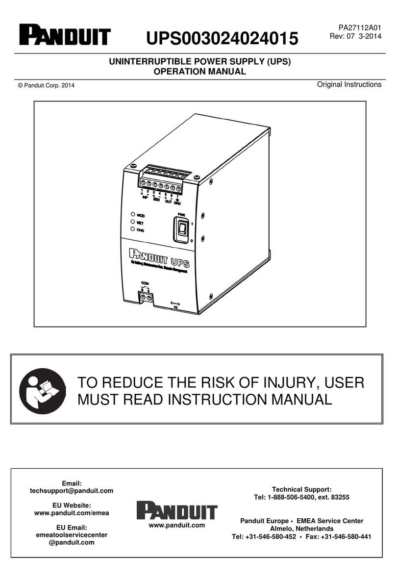
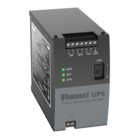
BACKGROUND1.1. The UPS003LSM is designed for redundant power back-up systems. The UPS003LSM is
intended to function only with the Panduit UPS003024024015 (UPS) unit. The UPS is rated for
a 24 VDC maximum output rating. The UPS LSM is connected to the main power supply line of
24 VDC. The UPS is connected along the secondary power supply line and is connected to the
UPS LSM, which allows the UPS to measure the current power consumption of the system.
This increases the accuracy of the estimated UPS potential hold time in the event the UPS is
required to supply power.
PURPOSE1.2. The purpose of this document is to provide the user with the information necessary to connect
the UPS LSM.
TERMS AND ABBREVIATIONS1.3. A....................
Ampere
DC.................Direct Current
PCB...............Printed Circuit Board
UPS...............Uninterruptible Power Supply
UPS LSM.......UPS Load Sense Module
V....................Volts
W...................Watts
©Panduit Corp. 2014 OPERATION MANUAL UPS003LSM
Page: 6 of 7
INSTALLATION1.4.
Figure 1: DIN Rail Installation
No minimum spacing to other modules is required for proper operation of the device.
To install the UPS LSM, place the module with the DIN rail guideway on the top edge of the
DIN rail and then snap it downwards and shown in Figure 1.
To remove, release the snap-on catch using a screwdriver and then detach the module from
the bottom edge of the DIN rail as shown in Figure 1.
NOTE: A 5A external overcurrent protection device is required to protect the UPS LSM.
Wiring Diagram
Figure 2: System Block Diagram

©Panduit Corp. 2014 OPERATION MANUAL UPS003LSM
Page: 7 of 7
Figure 3: Load Sense Module
Pins 3 and 4 of the load sense module are connected to the sense input terminals of the UPS.
Note that pin 3 of the current sense resistor must be connected to the “+” sense terminal and
pin 4 of the current sense resistor must be connected to the “-“sense terminal. Note that these
connections may not be reversed. These connections allow the UPS to measure the current
flow to the load under normal operation so that it can predict the run time when backup power
is being provided by the UPS.
Other manuals for UPS003LSM
1
Table of contents
Other Panduit UPS manuals

Panduit
Panduit smartzone 1-3KVA User manual

Panduit
Panduit UPS00100DC User manual

Panduit
Panduit Smartzone U01N11V User manual

Panduit
Panduit SmartZone User manual

Panduit
Panduit SmartZone User manual

Panduit
Panduit smartzone U01N11L User manual

Panduit
Panduit UPS003024024015 User manual

Panduit
Panduit smartzone 5-10KVA User manual

Panduit
Panduit UPS003LSM User manual