Pangolin PASS User manual

2022/07/28 09:15 1/26 PASS
Complete Help Docs - https://wiki.pangolin.com/
PASS
Professional Audience Safety System
User Manual for PASS version 1.5 March 2015
Important Information
PLEASE READ THIS ENTIRE MANUAL VERY CAREFULLY, INCLUDING THE LICENSE AGREEMENT AND
LIMITED WARRANTY FOUND IN THE BACK OF THIS MANUAL. FAILURE TO FOLLOW THESE INSTRUCTIONS
VERY CAREFULLY COULD LEAD TO AN INCREASED RISK OF AN UNSAFE LASER EXPOSURE.
This manual contains important information on how to install PASS in a laser projector, how to perform
adjustments, and how to make sure that the show remains safe – including a requirement to test your
laser projectors before each show and log the test results.
Introduction
Congratulations on selecting Pangolin’s Professional Audience Safety System, an important step toward
helping to keep your audiences safe from the potential hazards that laser projection systems may pose.
You have purchased a powerful and patented laser projector safety monitoring system for laser light
show usage.
Last update: 2021/04/27 20:10 safety:pass https://wiki.pangolin.com/doku.php?id=safety:pass
https://wiki.pangolin.com/ Printed on 2022/07/28 09:15
This manual serves as a brief introduction to PASS, so you can install it and get started.
Pangolin provides you with the PASS hardware board, connection cables, and this manual.
You must provide a laser projector including laser, scanners, shutter and power supply.
You must also use a light sensor to ensure maximum protection. An optional control panel may also be
used for maximum flexibility.
PASS is a sophisticated system which, when properly integrated into a laser projector and used with the
proper show presentation techniques and Pangolin software, can assist in maintaining the safety of
Audience Scanning laser shows.
PASS is barely bigger than a credit card, and yet it includes a set of very sophisticated and complete
protection systems.
PASS hardware is designed with multiple levels of redundancy and with circuitry that is designed to fail-
safe. In fact PASS is designed to maintain safety even in the face of several simultaneous failures.
Although the PASS hardware circuit board itself is designed with redundant circuitry, some of the
redundancy of the entire system is provided by external elements, such as the shutter, light sensor, and
projector interlock. This is why these additional items are very important, and mandatory for most uses
of PASS.
This manual discusses how to install, connect, and adjust PASS. You must read and fully understand this
manual before installing and using PASS. Pangolin also conducts private training sessions that integrators
must attend, before Pangolin will sell the PASS hardware.
NOTICE! Pangolin will only guarantee the proper operation of PASS when it is used in conjunction with
Pangolin software and control hardware (i.e. QM2000, FB3 or FB4). In addition, Pangolin strongly
recommends the use of only ScannerMAX series of scanners and servo drivers, or alternatively
Cambridge model 6210 or 6215 scanners with associated servo drivers made by Cambridge Technology.

2022/07/28 09:15 3/26 PASS
Complete Help Docs - https://wiki.pangolin.com/
Brief Theory of Operation
Ideally the PASS circuit is installed inside the projector, rather than externally. PASS may be inserted into
the ILDA (analog signal) signal stream, or alternatively inserted into the signal stream after your own
projector electronics (such as differential color receivers or scanner invert switches) but before the
scanner servo drivers and laser modulators or drivers. Given this location within the signal path, PASS is
able to interrupt the flow of the color signals, as well as forcibly close the shutter and open the projector
Interlock circuit if necessary.
PASS monitors the following projector-health-related properties:
Scanner power supply and internal PASS power supplies
Scanner position signals to derive:
Scanning velocity
Effect size
Horizon( “Protected Area”)
PASS logic system
Beam Power during both blanked and non-blanked periods
Control Panel signals, including ESTOP and Manual Reset (optional)
Power Supply monitor and critical fault response
When power is not applied to PASS, or when PASS detects that the power supply is not sufficient to
properly operate the laser projector, PASS will crowbar (short-circuit) the color signal inputs, and forcibly
close the shutter and intensity outputs. PASS will also open the projector interlock signal path (ILDA pins
4 and 17). As long as a fast shutter is located within the beam path and as long as the interlock signal
path is used within the projector, this dual action will prevent light from being emitted from the projector
under all circumstances.
Since the shutter is closed and projector interlock are opened during critical fault conditions, these two
external elements are able to work in a redundant fashion, incase either of these were to fail individually.
Because of this, PASS requires the use of both the shutter, and projector interlock.
Scanner Position Signal monitoring
PASS monitors the X and Y position signals and derives Euclidian vector velocity as well as effect size. If
the vector velocity is found to be below the Minimum Velocity (the minimum speed that the beam is
required to sweep, in X and/or Y, in order to be considered to be safe), and found to remain there for a
period longer than the Dwell Time (the time that a beam may remain at or below the minimum velocity
see page), PASS will blank (pull to zero volts) all color signals and the intensity signal. PASS will only do
this for the period of time that the beam is below the “Minimum Velocity”. As soon as the beam speeds
back up, or the beam enters a non-protected area (i.e. above the horizon if enabled), PASS will allow the
color signals to flow from the Input to the Output. The Effect Size has a similar result, and this is included

Last update: 2021/04/27 20:10 safety:pass https://wiki.pangolin.com/doku.php?id=safety:pass
https://wiki.pangolin.com/ Printed on 2022/07/28 09:15
in PASS as a measure of redundancy. If there is an effect that is scanning very quickly, and which would
satisfy the “Minimum Velocity”, but if this is a very small effect, PASS will blank the color and intensity
signals until the Effect Size resumes a safe level. The Effect Size is not adjustable on this version of PASS.
Note that during momentary interruptions of color and blanking signals, PASS does not affect the Shutter
output.
Control Panel Signals
A control panel may optionally be used with PASS. The control panel may have a ESTOP switch (i.e.
mushroom emergency stop switch), as well as a manual reset button, which may be embodied as a
keyswitch or push button. When a control panel is used with PASS, a Manual Reset is required in order to
activate PASS, and thus, start projector operation. In most cases, this is a simple keyswitch action but
could also be a simple momentary push button. And when a Control Panel is used, PASS continually
monitors the ESTOP button. If the ESTOP is pressed, PASS will immediately terminate all color and
intensity signals, and forcibly close the shutter. PASS will also open the projector interlock signal path
(ILDA pins 4 and 17).
Beam Power Monitor
The Beam Power Monitor is perhaps the most unique and important aspect of PASS. The Beam Power
Monitor is able to make sure that the light coming out of the projector conforms to what is expected.
When PASS commands that no light should be emitted from the projector, PASS will verify that this is so,
by observing the Beam Power Monitor. If light is coming out of the projector when it is not supposed to
be, PASS will forcibly blank the color and intensity signals, close the shutter, and open the projector
interlock signal path. PASS does this because this would be considered a critical problem. Likewise, if
PASS detects that light is commanded from the computer, but is not coming out of the projector, PASS
will take this same kind of critical action, because this could be a sign that the light sensor is not working.
And finally, PASS will measure the Beam Power against a “Maximum Safe Beam Power” adjustment, and
if it is exceeded, PASS will take the same critical action, forcibly blanking the color and intensity signals,
closing the shutter, and opening the projector interlock. Any of these conditions requires the power to be
recycled, or a Manual Reset. Under normal circumstances, this will never occur. There should always be
congruence between commanded power and actual light coming from the projector. And light coming out
of the projector above the “Maximum Safe Beam Power” level is, of course, also a sign of trouble. See the
section on “Using PASS with a light sensor” below for additional information.
2022/07/28 09:15 5/26 PASS
Complete Help Docs - https://wiki.pangolin.com/
PASS Logic System monitor
The PASS circuitry is implemented almost entirely in analog circuitry. There are logic circuits within PASS,
but these logic circuits are entirely combinatorial in nature. This means that the logic is made up of
simple AND and OR statements, which can be easily understood by peers in the safety community. There
are no sequential-logic circuits within PASS, nor are there any microprocessors, which could not be fully
validated.
In addition to the logic used by PASS to implement the basic safety features, PASS also includes a
separate layer or logic that actually watches the first logic layer, and verifies sanity. If there is a problem
within the PASS logic, the color and intensity signals are blanked, the shutter is closed, and the projector
interlock signal path is opened. The system will remain in that state until power is recycled, or until a
Manual Reset is performed.
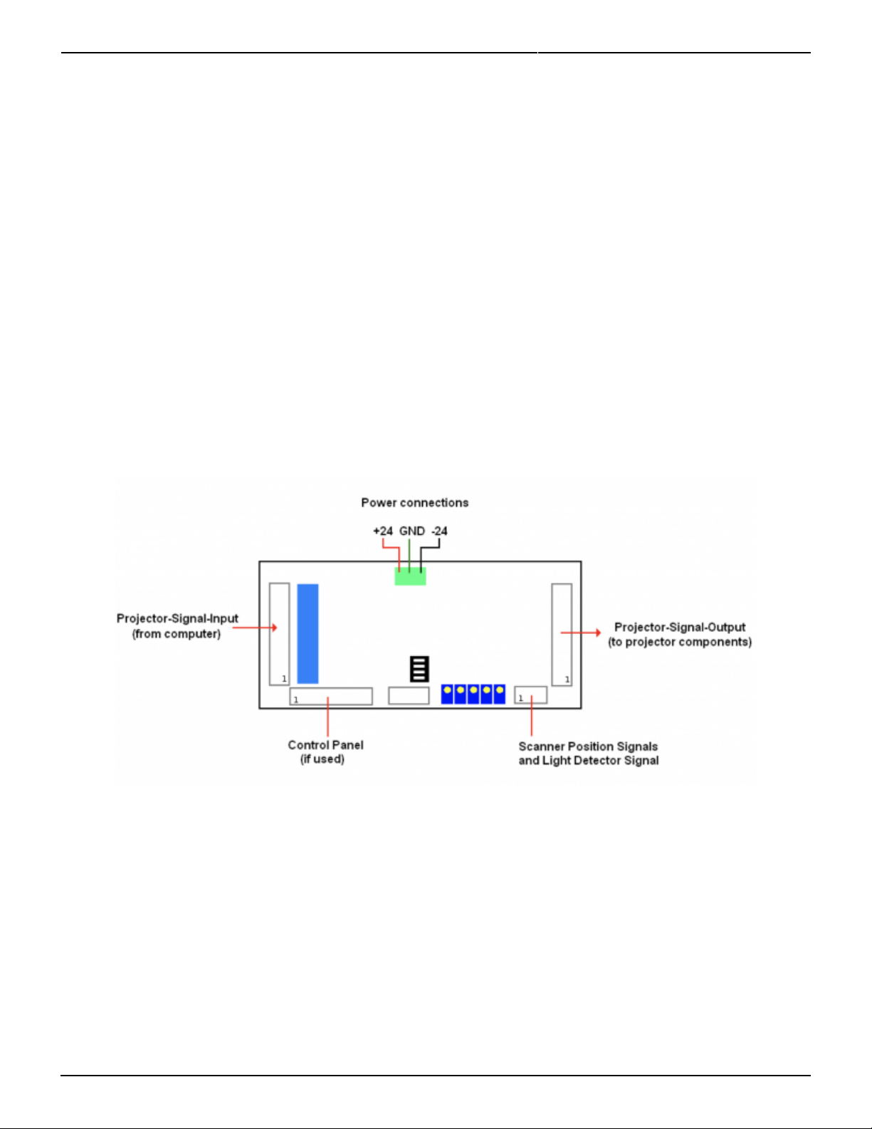
Layout and Connections
The general layout of PASS is shown above, with connectors identified.
Pangolin includes connectorized ribbon cables with PASS. These ribbon cables can be used directly,
allowing minimal effort to integrate PASS within a projector. When ribbon cables have a red stripe on one
side, the red stripe indicates the side of the cable associated with pin 1.
J801: Projector-Signal-Input
The Projector-Signal-Input to PASS may come directly from the DB- 25 input on the projector, or may
come after projector internal electronics that condition the color signals (for example, allow adjustment
of intensity for each color or scanner axis inversion and rotation). When PASS is used for direct projector

Last update: 2021/04/27 20:10 safety:pass https://wiki.pangolin.com/doku.php?id=safety:pass
https://wiki.pangolin.com/ Printed on 2022/07/28 09:15
input, a simple crimp-on DB-25 connector may be used, and crimped onto the Projector-Signal-Input
ribbon cable provided with PASS.
J802: Projector-Signal-Output
The Projector-Signal-Output connector on the PASS board should be parsed out into pairs of signals, and
then directed to various components within the projector. The signals and recommended connections are
discussed below. Note that since this is an IDC connector, the pin numbers do not correspond to the ILDA
pin-out on a DB-25. HOWEVER, if you crimp a DB-25-connector onto the output ribbon cable, then the
pins will correspond directly to the ILDA pin-out. This is because the pin designations of a DB-connector
are “in-line” while the pin designations of an IDC connector are “even and odd”.
Pins 1 and 2 correspond to the X+ and X- signal respectively. These should be connected to the
X+ and X- input on the X-axis scanner amplifier.
Pins 3 and 4 correspond to the Y+ and Y- signals respectively. These should be connected to the
Y+ and Y- input on the Y-axis scanner amplifier.
Note: There should NOT be a connection to the “signal ground” of any scanner amplifier. The only
“ground” connection to the scanner amplifier (or amplifiers) should be from the power supply itself.
Connecting to the “signal ground” on a scanner amplifier will introduce a ground loop, which may cause
distorted images. See the “Power and X-Y Position Signal Connections” on the following pages.
Pins 5 and 6 correspond to the Intensity/Blanking+ and Intensity/Blanking – signals respectively.
These may be used for a single-color projector or projectors that use a PCAOM for color.
Pins 7 and 8 correspond to the Projector Interlock loop pins 4 and 17 from the ILDA connector.
Note that PASS will interrupt this interlock signal loop in the event of a critical fault and
when power is insufficient, therefore it is MANDATORY that projector manufacturers
implement an interlock scheme that makes use of these signals. Ideally this interlock loop
should interrupt power to the lasers themselves, thus, in the event of a major problem, PASS can
interrupt power to the lasers. Alternatively the interlock loop may be routed to a SEPARATE shutter
placed just before the X-Y scanners and after the PASS light sensor.
Pins 9 and 10 correspond to Red+ and Red – color signals respectively. These should be
connected to the RED input on a PCAOM driver or directly to a laser diode driver.
Pins 11 and 12 correspond to Green+ and Green – color signals respectively. These should be
connected to the GREEN input on a PCAOM driver or directly to a laser diode driver.
Pins 13 and 14 correspond to Blue+ and Blue – color signals respectively. These should be
connected to the BLUE input on a PCAOM driver or directly to a laser diode driver.
Pins 15 and 16 correspond to Deep Blue+ and Deep Blue – color signals respectively. These are
most often not used by modern RGB laser projectors and thus, can be left unconnected. If they are
used, they should be connected to the DEEP BLUE input on a PCAOM driver or directly to a laser
diode driver.
Pins 17 and 18 correspond to Yellow+ and Yellow – color signals respectively. These are most
often not used by modern RGB laser projectors and thus, can be left unconnected. If they are used,
they should be connected to the YELLOW input on a PCAOM driver or directly to a laser diode
driver.
Pins 19 and 20 correspond to Cyan+ and Cyan – color signals respectively. These are most often
not used by modern RGB laser projectors and thus, can be left unconnected. If they are used, they

2022/07/28 09:15 7/26 PASS
Complete Help Docs - https://wiki.pangolin.com/
should be connected to the CYAN input on a PCAOM driver or directly to a laser diode driver.
Note that for the color signals above, ideally, any Laser Diode Driver should have differential input, and
you should connect both the + and – color signals from the PASS board directly to those drivers.
Pins 21 and 22 correspond to the Z+ and Z – signals respectively. In most cases, laser projectors
do not use these signals directly and in fact, when used with certain pieces of Pangolin software,
these signals correspond to a Safety Coordinate System. It is recommended that these be left
unconnected.
Pin 23 is connected to the ILDA input connector pin 12. This signal is reserved by ILDA for a light
sensor output, but it is essentially unused by all manufacturers. It is recommended that this pin be
left unconnected.
Pin 24 is connected to the ground connection of PASS. It is recommended that this only be used as
a ground reference for the shutter driver, and nothing else.
Pin 25 is the main Shutter output. Under normal circumstances the state of this signal will
correspond directly to pin 13 on an ILDA input connector. However, in the event of a major fault,
PASS will forcibly close the shutter using this signal. It is therefore MANDATORY that this be
connected to a shutter driver. For maximum safety, the shutter should be a fast type of shutter,
and one that also will fail-safe. This means that in the event of a mechanical or electrical failure of
the shutter, it will remain closed due to the mechanical design of the shutter. Pangolin highly
recommends shutters manufactured by the company called nm Laser Products
(http://www.nmlaser.com).
J803: Scanner Position and Light Detector Inputs
Pin 1 provides +5V output, which should only be connected to the PASS light sensor.
Pin 2 is the PASS light sensor input, which ranges from 0V to +5V.
Pin 3 and Pin 5 correspond to the Signal Ground connection of PASS. Pin 3 should be connected
to the PASS light sensor. Pin 5 may or may not be connected to the scanner amplifier, depending
on circumstances described below.
Pin 4 corresponds to the X Position Signal. This should be connected to the X-axis scanner
amplifier.
Pin 6 corresponds to the Y Position Signal. This should be connected to the Y-axis scanner
amplifier.
J804: Control Panel Signals

Last update: 2021/04/27 20:10 safety:pass https://wiki.pangolin.com/doku.php?id=safety:pass
https://wiki.pangolin.com/ Printed on 2022/07/28 09:15
PASS may be controlled by, and may illuminate LEDs on an external control panel that is connected to
PASS. Below is a description of the control panel connections. When PASS is not connected to an external
control panel, then PASS will automatically reset into a “ready” state shortly after power up. When PASS
is connected to an external control panel, then PASS will not power up in a “ready” state and instead, will
wait for the “Manual Reset” from the control panel.
Note that some jurisdictions including the U.S.A. require a manual reset in order to activate the projector
after power up. The PASS control panel connector may be used to help facilitate this feature.
Also note that the signals presented to this connector are generally connected directly to PASS logic
circuits. The signals are not protected from ESD or other electrical faults. For that reason, it is
recommended that any external signals that are connected to this connector be short (i.e. don’t connect
a 30 meter long cable from the external box to the PASS board…)
Pin 1 is the active input that corresponds to an external Emergency Stop (ESTOP) switch, such as a
pushbutton or red “mushroom” type switch. When this pin is connected to Pin 2 (ground), ESTOP is
activated. When Pin 1 is left floating, then ESTOP is inactive and the projector will be allowed to
operate normally.
Pin 3 is the active input that corresponds to a Manual Reset. This may be connected to pin 4
(ground) through a momentary pushbutton switch or a key-switch.
Pin 5 is an active input that indicates that a control panel is being used. Pin 5 must be connected
to Pin 6 when a control panel is used. If Pin 5 is not connected to Pin 6, then PASS will not wait for a
manual reset when power is first applied.
Pins 7 and 8 provide +5V to the control panel. These may be used in conjunction with LEDs on the
control panel.
Pins 9 and 10 correspond to Ground. These may also be used in conjunction with LEDs on the
control panel.
Pin 11 is an output, which corresponds to the horizon detector within PASS. If this signal is LOW, it
indicates that the Y position is below the horizon (within the audience area). If this signal is HIGH
(approximately 4 volts), it indicates that the Y position is above the horizon. This signal may be
routed through a resistor to an LED or pair of LEDs (bi-color pair) to give an indication on the
control panel as to where the beam is within the Y space.
Pin 13 is an output, which corresponds to the velocity detector within PASS. If this signal is LOW, it

2022/07/28 09:15 9/26 PASS
Complete Help Docs - https://wiki.pangolin.com/
indicates that the beam velocity is OK, and that PASS will not actively suppress laser output
because of velocity (PASS may suppress laser output for other reasons however). If this signal is
HIGH (approximately 4 volts), it indicates that the beam velocity is too slow, and that PASS will
actively suppress laser output. This signal may be routed through a resistor to an LED or pair of
LEDs (bi-color pair) to give an indication on the control panel as to the disposition of the velocity.
Pin 15 is an output, which corresponds to the light detector within PASS. If this signal is LOW, it
indicates that the light that is detected by PASS is above the “Maximum Safe Laser Power”
threshold setting. If this signal is HIGH (approximately 4 volts), it indicates that the light detected is
below the “Maximum Safe Laser Power” threshold setting. Under ordinary circumstances, this will
never be LOW. This signal may be routed through a resistor to an LED or pair of LEDs (bi-color pair)
to give an indication on the control panel as to the disposition of the light detected by the light
sensor.
Pin 17 is an output, which corresponds to whether or not PASS is “ready”. Once PASS has given a
“armed” indication on Pin 19, and then once the “Manual Reset” is activated (by connecting Pin 3
to Pin 4), this signal will go HIGH, indicating that PASS will allow color signals to flow through the
PASS board to the internal laser projector components. This signal will remain HIGH as long as
there are no major faults detected, such as a Power Supply fault, Light Detector fault, other
detectable major fault, or ESTOP being activated. This signal may be routed through a resistor to
an LED or pair of LEDs (bi-color pair) to give an indication on the control panel as to whether or not
PASS is active.
Pin 19 is an output, which corresponds to whether or not PASS is ready to be activated (“armed”).
If this signal is HIGH, it indicates that the power supply is OK, ESTOP is not activated, and light is
not detected and thus, PASS may be activated by performing a “Manual Reset”. This signal may be
routed through a resistor to an LED or pair of LEDs (bi-color pair) to give an indication on the
control panel as to whether or not a Manual Reset can be performed. If used, this LED should
ideally be placed near the “Manual Reset” push button or keyswitch.
Pin 12 is an output, which corresponds to whether or not the computer feeding the ILDA input has
commanded that light come out of the laser projector or not. If this signal is HIGH, it indicates that
the light that PASS has detected that the computer has requested more than approximately 50%
beam power from the computer. If this signal is LOW, it indicates that the computer is commanding
50% or less beam power from the computer. This signal may be routed through a resistor to an
LED or pair of LEDs (bi-color pair) to give an indication on the control panel as to whether or not the
computer has commanded light to come out of the projector.
Pin 14 is an output, which corresponds to the condition of the power supply, both within PASS and
supplying the scanner amplifiers. If this signal is HIGH, it indicates that the power supply feeding
the scanner amplifiers is 19 volts or higher. It also indicates that all of the power supplies within
PASS itself are also within their acceptable ranges. If this signal is LOW, it indicates that there is a
power supply problem of some kind. This signal may be routed through a resistor to an LED or pair
of LEDs (bi- color pair) to give an indication of the state of the power supplies.
Status LED signals on the Control Panel connector
Pin 16 is a “Status LED number 1”. If this signal is LOW, it indicates that a power supply fault has
been detected.
Pin 18 is a “Status LED number 2”. If this signal is LOW, it indicates that the PASS light sensor
detected a light level that exceeded the “Maximum Safe Light Level” while the Y position was
below the horizon.
Last update: 2021/04/27 20:10 safety:pass https://wiki.pangolin.com/doku.php?id=safety:pass
https://wiki.pangolin.com/ Printed on 2022/07/28 09:15
Pin 20 is a “Status LED number 3”. If this signal is LOW, it indicates that PASS tried to extinguish
light from coming out of the projector, but that the PASS light detector still detected light output.
This would occur if a PCAOM or Laser Diode Driver continued to output light after being told not to.
This would also occur if the “Minimum light level” adjustment of PASS is not set correctly. And
finally, this might also occur if PASS did not detect light coming out of the computer even though
the computer commanded light output. This would indicate either a laser failure or light detector
failure.
Note that unlike the other LED outputs on the control panel connector, the “Status LED” outputs will
“latch” in the event that a fault is detected. They will remain in the latched state until a Manual Reset
occurs. This allows you to determine the cause of any detected faults.
The “Status LED” signals may be routed through a resistor to an LED on the control panel to give an
indication of any faults that have been detected.
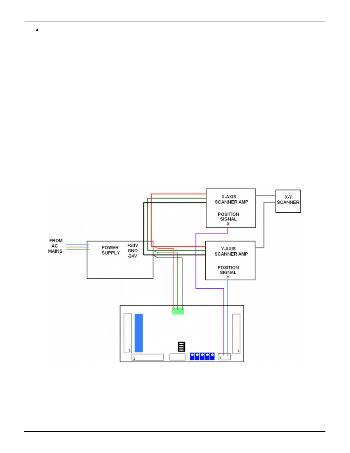
PASS Power and X-Y position signal connections
PASS monitors the power supplies that feed the scanner amplifiers. This voltage can be between +/-20
volts and +/- 30 volts. The manor in which you connect PASS to the power supply and to the scanner
amplifiers depends heavily upon whether you are using two separate single-axis scanner amplifiers, or
one dual-axis scanner amplifier.
If you are using two separate single-axis scanner amplifiers, the recommended connections are shown
Table of contents
Popular Safety Equipment manuals by other brands

Lanex
Lanex PB-20 instruction manual

SKYLOTEC
SKYLOTEC ANCHOR ROPES Instructions for use

Besto
Besto Buoyancy Aid 50N Instructions for use

TEUFELBERGER
TEUFELBERGER NODUS Manufacturer's information and instructions for use

Troy Lee Designs
Troy Lee Designs Tbone Product owners manual

Innova
Innova Xtirpa Instruction and safety manual

bolle SAFETY
bolle SAFETY B810 quick start guide

SHENZHEN FANHAI SANJIANG ELECTRONICS
SHENZHEN FANHAI SANJIANG ELECTRONICS A9060T instruction manual

Hiltron security
Hiltron security POWER8E Installation and use manual

Salewa
Salewa MTN SPIKE user manual

Hatco
Hatco B-950P installation guide

Sitec
Sitec TX MATIC operating manual


