Panini Vision X User manual

OPERATOR MANUAL Page 0 General
Operator Manual


OPERATOR MANUAL Page 2 Preface
CONTENTS
0. Preface
1. General
1.1 Audience
1.2 Safety Precaution
1.3 If the machine is damged
2. Learning about the Panini Vision X
2.1 Packaging List
2.2 External Parts Description
2.3 internal Parts Description
3. Operating your Panini Vision X
3.1 Document Support Installation
3.2 Extension Plate Installation
3.3 Power Cables Connection
3.4 USB2 Cable Connection
3.5 Ink-jet Cartridge Installation
3.6 Pocket Length Adjustment

OPERATOR MANUAL Page 3 Preface
4. Getting Started
4.1 Status Light
4.2 How to Prepare and Load Checks
4.3 Clearing Jams
5. Maintance
5.1 Cleaning the Transport
5.2 Cleaning the Contact Image Sensors
5.3 Cleaning the Ink-Jet Cartridge
5.4 Cleaning Photocells Detector
5.5 Replacing the Feeder and Separator Roller
5.6 Cleaning the Reading Transport Belt
5.7 Install the External Covers
6. Specifications
6.1 Technical Specifications of the Panini Vision X
6.2 Technical Specifications of the PC
7. Vision X AGP Addendum
8. Vision X P Addendum
9. Multilingual WEEE Disposal Procedure and Safety Precautions

OPERATOR MANUAL Page 4 Preface
Fourth Edition,
July 2011
© 2011
PANINI SpA
Via Po, 39
10124 Torino, Italy
PANINI NORTH AMERICA
(Subsidiary)
577 Congress Park Drive
Dayton, OH 45459
USA
PANINI LIMITADA
(Subsidiary)
Rua Joaquim Floriano,
871 11ºA
São Paulo
Brazil
www.panini.com
This manual and the software described in it are protected under
the Panini S.p.A Copyright. All rights reserved. Reproduction of
thismaterial in any form without the express written consent of
Panini SpA or its subsidiaries is prohibited.
WARRANTY OF ANY KIND, EXPRESS OR IMPLIED, INCLUDING,
BUT NOT LIMITED TO THE IMPLIED WARRANTIES OF
MERCHANTABILITY AND FITNESS FOR A PARTICULAR
PURPOSE. PANINI SpA MAY MAKE IMPROVEMENTS AND OR
CHANGES IN THE PRODUCT(S) AND OR THE PROGRAM(S)
DESCRIBED IN THIS MANUAL AT ANY TIME AND WITHOUT
NOTICE.
This manual could contain technical inaccuracies or typographical
errors. Changes are periodically made to the information herein;
these changes will be incorporated in new editions of this
publication.

OPERATOR MANUAL Page 5 Preface
Trademark Acknowledgement
PANINI, Vision X, Vision API, ICR Vision and MICR Plus are trademarks or registered trademarks of Panini
SpA.
The mark affixed to the product certifies that
the product satisfies the basic quality requirements.
The Panini Vision X is also UL 950 compliant
NOTE: This equipment has been tested and found to comply with the limits for a Class A digital device,
pursuant to Part 15 of the FCC Rules. These limits are designed to provide reasonable protection against
harmful interference when the equipment is operated in a commercial environment. This equipment
generates, uses, and can radiate radio frequency energy and, if not installed and used in accordance with
the instruction manual, may cause harmful interference to radio communications. Operation of this
equipment in a residential area is likely to cause harmful interference in which case the user will be required
to correct the interference at his own expense.
© 2011 PANINI S.p.A., ALL RIGHTS RESERVED

OPERATOR MANUAL Page 6 Preface
Proper Disposal of WEEE
FOR COUNTRIES IN THE EUROPEAN UNION (EU)
The European Commission of the European Union has determined that electrical and electronic equipment
on the market today contain parts and components that may be properly reused or recycled to reduce
quantities of materials ultimately disposed in landfills and other disposal arenas. To address this
determination, waste electrical and electronic equipment (WEEE) should not be collected or disposed with
unsorted waste from private households or businesses. Rather, it must be collected separately. Dumping of
these devices at unequipped and unauthorized places may have hazardous effects on health and
environment. Offenders will be subjected to the penalties and measures laid down by the law.
crossed-out dustbin symbol to indicate the requirement for separate collection of electrical and
electronic equipment put on the market after August 13, 2005, according to the WEEE directive
2002/96/EC (and subsequent amendments) and your national laws.
To dispose of our devices correctly:
Contact the Local Authorities or local distributor, who will give you the practical information you need and
the instructions for handling the waste correctly, for example: location and times of the waste collection
centres, etc.
When you purchase a new device of ours, give a used device similar to the one purchased to our
distributor for disposal.
FOR OTHER COUNTRIES (NOT IN THE EU)
The treatment, collection, recycling and disposal of electric and electronic devices will be carried out in
accordance with the laws in force in the country in question.

OPERATOR MANUAL Page 7 Preface
0. Preface
Here is an overview of the manual layout:
introduces you to all the general information regarding the manual or the Panini
Vision X.
introduces you to all the major components of your machine.
Chapter 3: describes simple installation procedures.
Chapter 4: explains how to operate the Vision X.
Chapter 5: describes how to solve problems that you may encounter using this machine.
Chapter 6: lists the main functions of the Vision X and the features of the PC.
Chapter 7
Chapter 8
Chapter 9: explains how to dispose
the Vision X in 12 languages.

OPERATOR MANUAL Page 8 General
1. General
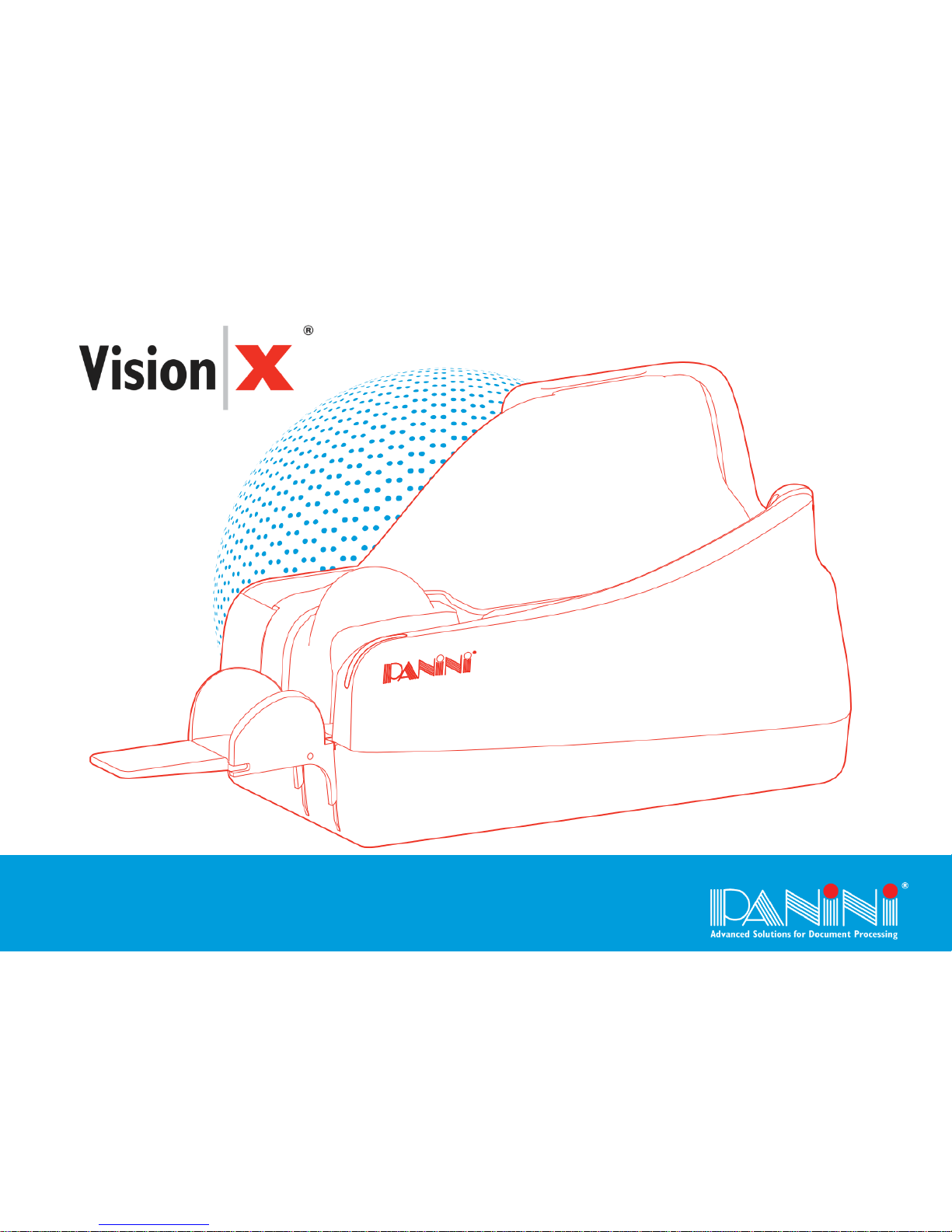
Congratulations on your selection of the Panini Vision X!
The Panini Vision X is the next generation check scanning platform designed specifically for distributed
check capture.
With a small footprint, sleek design and quiet operation, the Panini Vision X series is the ideal choice for a
wide array of applications such as: Teller Window, Back Counter, Remote Deposit Capture, Microfilm
Replacement, Cash Vault, Brokerage Houses, Accounts Receivable Conversion (ARC), just to name a few.
The Panini Vision X incorporates the latest, state-of-the-art technology and the latest standards for check
processing in the marketplace. It is characterized by its ease of use and scalability.
Panini Vision X image capture capabilities have been optimized in order to guarantee image integrity and
perfect data readability despite variations in documents processed, operational skills, environmental and
usage conditions.
MICR reading technology available with the Panini Vision X is comparable to the larger and faster reader
sorter, thanks to the Panini MICR PlusTM technology.
Taking advantage of the most up to date technology, the Panini Vision X connects to computers via USB2.0
interface, allowing for fast data transfer at no additional cost.
A rear Ink-Jet endorser can also be found on the Panini Vision X.
The Panini Vision API is standard on the Vision X, guaranteeing easy and reliable software integration.
Finally, the Panini Vision X has been designed specifically to allow for entire track accessibility, including
scanner area, for easy intervention and for maintenance purposes.

OPERATOR MANUAL Page 9 General
1.1 Safety Precautions
Before you begin operating or servicing your Vision X as instructed in this manual, please make sure you
read and understand these important safety instructions.
Dress safely. Do not wear loose clothing, long hair or jewelry that can become entangled in moving
parts.
Do not allow anything to rest on the power cord. Do not locate the Vision X where people may walk
on the cord.
Always unplug the Vision X before cleaning.
Do not attempt to service or repair the Vision X, except as instructed elsewhere in this manual.
Attempting to service or repair the external power supply of the Vision X may expose you to
dangerous voltage points or other risks.
Refer all servicing to qualified service personnel.

OPERATOR MANUAL Page 10 General
1.2 If the Machine is Damaged
Unplug the Vision X from the wall outlet and refer servicing to qualified personnel under the following
conditions:
If the power cord is damaged or frayed.
If liquid has been spilled into the product.
If the equipment has been exposed to rain or water.
If the equipment does not operate normally when the operating instructions are followed.
If the equipment has been dropped or damaged.
If the equipment exhibits a distinct change in performance, indicating a need for service.
Adjust only those controls and replace only those items that are covered by the instructions in this manual.
If you attempt to make adjustments not covered in this manual, you may damage the equipment and void the
warranty.
Unauthorized adjustments or repairs may result in the need for extensive work by a qualified technician to
return the equipment to its proper working condition.

OPERATOR MANUAL Page 11 Learning about the Panini Vision X
2. Learning about the Panini Vision X
The Panini Vision X is a compact, easy-to-use and quiet scanner.
The Panini Vision X automatically scans the front and/or rear of checks while simultaneously capturing the
Magnetic Ink Character Recognition (MICR) code line. An optional Ink-Jet endorser prints alphanumeric
characters on the rear of items. Any of the Windows standard fonts can be used for printing endorsements.
The Panini Vision X is connected to a PC via a USB2.0 interface.
2.1 Packaging List
The Panini Vision X package includes:
-Operator Manual
-Accessories Box*
-Panini Vision X scanner unit
-Power cable
(*) The accessories box contains:
-Jet Cartridge
(Panini P/N: CA-109765)
Cartridge not included with No Ink Jet (NJ) versions
-Jet Plastic Lever (adapter for HP 51604A cartridge)
Supply

OPERATOR MANUAL Page 12 Learning about the Panini Vision X
2.2 Removing the Panini Vision X from the Packaging
1. Remove the Accessories box and the power cable out of the packaging.
2. Holding the packaging down with one hand, lift the Vision X together with the packing materials making
use of the plastic handle.
Attention:
only to extract the device from its packaging.
During unpackaging, do not remove or pull the Mylar blades in the exit pocket. (see
A, B and C in the image above)
Plastic Handle

OPERATOR MANUAL Page 13 Learning about the Panini Vision X
2.2 External Part Description
This section describes the major components of the Panini Vision X.
The component names introduced here and shown in the figures are used throughout this manual.
Pocket Extension
Document Pressure Plate
Extension Plate
Bottom Cover
Feeder extension
Inner Cover
Outer Cover
Magnetic Card
Reader (optional)
LED Status Indicator

OPERATOR MANUAL Page 14 Learning about the Panini Vision X
2.3 Internal Part Description
1. Document Pressure Plate
2. LED Board
3. Feeder Roller
4. Feeder Sensor
5. Rear Separator Roller
6. Front Separator Rooler
7. Pre-Magnetization Heads
8. Pressure Roller
9. MICR reading head
10. Synchronization Sensor
11. Ultrasonic Double Feeding Sensor
12. Transport Roller
13. Ink-Jet Cartridge Cradle
14. Rear Image Camera
15. Front Image Camera
16. Pocket Sensor
17. Transport Belt
18. Interlock Board
19. Feeder Motor
1
2
3
4
5
6
7
10
9
11
12
8
13
14
15
16
17
18
19

OPERATOR MANUAL Page 15 Operating your Panini Vision X
3. Operating your Panini Vision X
3.1 Document Support Installation
Insert the feeder extension in the slot uncovered by pushing back the document pressure plate.
Installation is correct if the feeder extension is at the same level as the beninning of the scanner platform.
Feeder
Extension
Document
Pressure Plate
Slot

OPERATOR MANUAL Page 16 Operating your Panini Vision X
3.2 Extension Plate Installation
The feeder extension is designed to support all documents anticipated to be processed by the Vision X.
Markets or applications that process a large number of long documents (longer than 8 inches) may find it
necessary to apply the optional extension plate for better document support, reducing the risk of image
skewing, MICR rejects, etc. Assembly is made by sliding the extension plate, face side up, along the bottom
side of the feeder extension into the support notches until the plate snaps into place. The lock tabs should
securely fit into the round holes and the short and long tabs should be fully inserted into the support notches.
To remove, firmly grip the feeder extension and the extension plate and pull apart.
Long and short tabs should be fully
inserted into the support notches
Lock tabs should be
in round holes
Extension plate
face side up
Feeder extensione
support notches

OPERATOR MANUAL Page 17 Operating your Panini Vision X
3.3 Power Cable Connection
Before connecting the scanner to your PC, make sure to position the unit on a flat surface near the PC, away
from direct light and from electromagnetic equipment.
1. Plug the power cord connector in the power supply socket.
2. Plug the Power Supply cable in the Vision X power connector.
Warning:
The electromagnetic emission from a CRT monitor can produce interference and affect the
MICR reading; therefore place the Vision X as far as possible from the CRT.
The Vision X will be in compliance to the standard IEC/EN 60950-1 and UL 60950-1 only using
the Power Supply model DSA-0421S-28 1 42 provided with the machine.
3. The Vision X should be plugged into a dedicated electrical power outlet. The socket outlet shall be
installed near the equipment and shall be easily accessible. The power supply will be 100-240 VAC (no
power selection required), and the frequency 50/60 Hz. If you are not sure of the type of power available,
consult your Service Representative or local power company.
Note: There is no LED power indication upon connecting the Vision X. LED status indicators only
illuminate when the application connects to the Vision X unit. See section 4.1.

OPERATOR MANUAL Page 18 Operating your Panini Vision X
3.4 USB Cable Connection
Connect the USB cable to the USB 2.0 port located on the rear
side of the scanner, and then connect the other end of the cable to
an available USB 2.0 port on the PC.
3.5 Ink-Jet Cartridge Installation (*Optional)
Remove the inner cover (see section 5.1 for details). Take a new Ink-Jet cartridge out from its package. Do
not touch the ink with your fingers or clothing: it will stain. Angle the front side of the cartridge downwards
and face the two pins with the two holes in the cradle. Gently push down the rear side of the cartridge until it
snaps in the plastic retainer.
* If the unit was purchased without the endorser option then the unit is shipped without an ink cartridge and that one is
not needed to run the device.
Ink-Jet Cartridge Panini P/N:
CA-109765
Castridge cradle
Plastic retainer
USB cable

OPERATOR MANUAL Page 19 Operating your Panini Vision X
3.6 Pocket Length Adjustment
Adjust the pocket length by inserting the longest document that will be processed in the pocket. Move the
pocket extension left or right until a space of
document and the end of the pocket extension.
Table of contents
Other Panini Scanner manuals

Panini
Panini EverneXt User manual

Panini
Panini I:Deal User manual

Panini
Panini Vision NeXt User manual

Panini
Panini My Vision X Manual

Panini
Panini Vision 1 User manual

Panini
Panini My Vision X User manual

Panini
Panini My Vision X User manual

Panini
Panini mI:Deal User manual

Panini
Panini My Vision X User manual