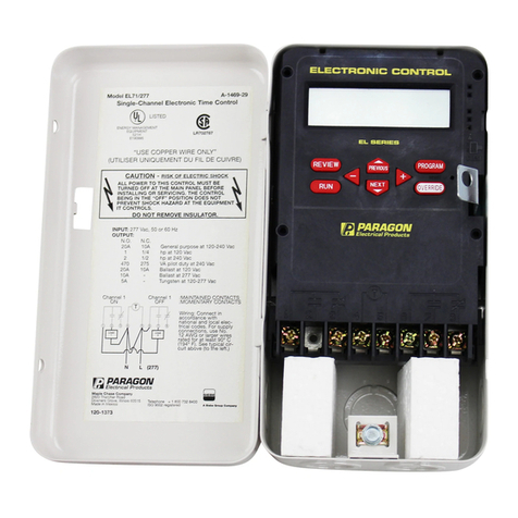
Paragon EL712 Instruction manual

EL712 - Twelve Channel
Electronic Time Control
General Instructions
CONTENTS
INTRODUCTION . . . . . . . . . . . . . . 2 CONFIGURATION . . . . . . . . . . . .8
SPECIFICATIONS . . . . . . . . . . . . . . 2 ASTRO . . . . . . . . . . . . . . . . . . . .8
PROGRAMMING CAPABILITIES . 2 EVENT . . . . . . . . . . . . . . . . . . .10
ELECTRICAL . . . . . . . . . . . . . . . 3 INPUT CONFIGURATION . . . . .10
ENVIRONMENTAL . . . . . . . . . . . 4 SENSOR EVENT . . . . . . . . . . . .11
PHYSICAL. . . . . . . . . . . . . . . . . . 4 HOLIDAY . . . . . . . . . . . . . . . . .11
FUNCTIONAL DESCRIPTION . . . . . 4 OVERRIDE . . . . . . . . . . . . . . . . .13
FRONT PANEL LAYOUT . . . . . . . 4 RUN . . . . . . . . . . . . . . . . . . . . .13
INPUT CONNECTIONS . . . . . . . . 4 ACCESSORIES . . . . . . . . . . . . . .14
KEYPAD DESCRIPTION. . . . . . . . 5 TEMPERATURE SENSOR . . . . .14
HIERARCHY OF CONTROL . . . . 6 LIGHT SENSOR . . . . . . . . . . . .14
PROGRAMMING . . . . . . . . . . . . . . 7 COMPUTER SOFTWARE . . . . .14
PROGRAMMING OVERVIEW. . . . 7 APPLICATION EXAMPLES . . . . . .14
MEMORY CLEAR . . . . . . . . . . . . 7 PROGRAMMING WORKSHEETS .20
SET TIME . . . . . . . . . . . . . . . . . . 7
http://waterheatertimer.org/Paragon-timers-and-manuals.html

• 3 Holiday Schedules - Each of these 36 holidays can be assigned to one of three holiday
schedules (A,B or C). For example if July 4th is assigned to holiday schedule A, then on July 4th
only those events and sensor events containing holiday A in their day fields will be executed.
• Keyboard Override - Toggles the current output state; begins immediately when initiated and
remains in effect until overridden again or until the next programmed event occurs.
• Astro - Optional Astro feature assignable to any combination of channels. Astro will auto-
matically keep track of the changing sunrise and sunset times throughout the year without
the need of a photocell. The Astro feature will keep assigned output(s) off during daylight
hours.
• Selectable Clock Format - 12 hour (am/pm) or 24 hour clock format.
• Stagger Up - Optional stagger up time between channels, after a power outage; selectable
from 5 seconds, 15 seconds, 30 seconds, 1 minute, 5 minutes, 10 minutes, and 15 minutes.
• Momentary - The EL712 will normally be configured as maintained. The momentary option is
intended for use with latching relays. An EL712 configured as momentary will only have 6
channels. Relays 1, 3, 5, 7, 9 and 11 will provide a one second ON pulse for channels 1, 2,
3, 4, 5 and 6, respectively. Relays 2, 4, 6, 8, 10 and 12 will provide a one second OFF pulse
for channels 1, 2, 3, 4, 5 and 6, respectively. See example 2 on page 16 for more details.
• Computer Interface - The controls can be programmed and reviewed by a local personal
computer using Pecosoft.EL software (sold separately).
Electrical:
1. Power Requirements -
Input Voltage 24, 120, 208, 240 or 277 Vac, 50/60 Hz
2. Outputs - Twelve SPDT relays with contacts rated as follows:
Normally Open Contacts: 20 amp resistive or inductive at 120-277 Vac
1 HP at 120 Vac
2 HP at 208-277 Vac
5 amp tungsten at 120-240 Vac
20 amp ballast at 120 Vac
10 amp ballast at 208-277 Vac
470 VA at 120-240 Vac
Normally Closed Contacts: 10 amp resistive or inductive at 120-277 Vac
1/4 HP at 120 Vac
1/2 HP at 208-277 Vac
3 amp ballast at 120-277 Vac
275 VA at 120-240 Vac
3. Wiring - Relay contact terminals can accommodate 10-16 AWG
- Power input terminals can accomodate 12-18 AWG
- Sensor/override input terminals can accommodate 18-22 AWG
4. Power Outage Carryover - The program and time of day are maintained during a power
outage for a minimum of 2 days by means of a capacitor. After two days, a lithium battery
takes over and provides a minimum accumulated carryover of 1 year. The lithium battery
should provide over 10 years of carryover protection.
Environmental:
1. Temperature - Operating: -20 F (-29 C) to 140 F (60 C)
2. Relative Humidity - 10 to 90% RH (non-condensing)
3. The EL712 should be mounted indoors in an environment that is free from excessive conta-
minants such as oil, moisture and dirt.
Physical: Enclosure Dimensions
Enclosure: NEMA 1 drawn steel with lockable hasp
W = 14.3" (36.4cm), H = 16.1" (40.9 cm), D = 6.1" (15.6 cm), Weight: Approx. 17.7 lbs. (8.0 kg)
Introduction
The EL712 is a twelve-channel, electronic time control that provides simple, inexpensive con-
trol of lighting, HVAC, motors, pumps, bell-ringing or any electrical load with a time-of-day
schedule. The control may be utilized as a 24 hour, 7 day or full year (365 day) control.
The EL712 allows for the programming of 128 events. An event could be an ON, an OFF, one
of four user-defined durations or one of four user-defined duty cycle patterns. In addition, up
to 32 sensor events can be programmed to allow control based on temperature & light level.
Other parameters can be used; contact the factory for information.
The EL712 is a member of the EL series of time controls, that also includes the EL71, EL72, EL74,
and EL78 (1, 2, 4 and 8 channel, respectively). All are versatile, yet easy to program. A simple key-
pad combined with a large, user-friendly display takes the frustration out of programming.
Specifications
Programming Capabilities
•128 Events - An event can be an ON, an OFF, one of four user-defined durations or one of
four user-defined duty cycle patterns. Each event can be assigned to any channel. Each
event can be assigned to any day or any combination of days, including the three holiday
schedules.
•4 Durations - Each duration can be programmed from 1 second to 23 hours,59 minutes and
59 seconds.
•4 Duty Cycle Patterns - Each duty cycle pattern can be programmed with ON durations and
OFF durations from 1 second to 23 hours, 59 minutes and 59 seconds.
•8 User-Defined Inputs - Each input can be independently defined as one of two override
types, an enable input or as one of four sensor types.
•ON With Off Delay Override Input - Provides a retriggerable override input that is assignable
to any combination of outputs. The affected output(s) will be overridden ON with the closing
of the input and remain ON as long as the input is closed. When the input is opened, the
output(s) will remain ON for the length of the off delay. The off delay is programmable from 0
seconds to 23 hours, 59 minutes and 59 seconds. Closing the input during the off delay will
retrigger the override.
•Toggle Type Override Input - Provides a toggle type override input that is assignable to any
combination of outputs. Closing the input causes the affected output(s) to be toggled to the
opposite state and remain in that state until the occurrence of the next programmed event.
An optional timed-on from 1 second to 23 hours, 59 minutes and 59 seconds can be pro-
grammed. Upon completion of this timed-on, the affected output(s) will return to the pro-
grammed state unless toggled off.
•Enable Input - The enable input is assignable to any combination of outputs. The enable
input acts as a switch which opens and closes in series with the output(s). When open, the
load(s) will remain off. When closed, the output(s) follow the scheduled events.
•Sensor Input - The inputs can be configured as one of four sensor types:
F = degrees Fahrenheit (-40 to 215)
C = degrees Celsius (-40 to 102)
L = light level (0 to 100)
U = undefined (0 to 255)
•32 Sensor Events - A sensor event will control a channel based on programmable on/off
sensor levels. Each sensor event can be assigned to any day or combination of days,
including the three holiday schedules.
•Optional Daylight Savings Correction - Programmable as a day of the month (i.e. 1st Sunday
in April / last Sunday in October)
•Leap Year Correction to the Year 2100
•10 Single Day Holidays - (e.g. July 4th)
•10 Day of Month Type Holidays - (e.g. last Monday in May)
•10 Holiday Durations - Programmable from 1 to 366 days (e.g. June 9th to August 27th)
•6 Specific Holidays - Each holiday can be optionally selected
Good Friday Easter Sunday Easter Monday
Boxing Day Victoria Day Thanksgiving Thursday and Friday
32
Keypad Description
Master Reset - Clears time and program. Display will show "MEM CLR". The reset switch is
accessed by inserting a pointed object, such as a paper clip, into the reset hole
to the right of the keypad.
PROGRAM - This key allows the user to add, delete or change parameters (events, time,
holidays, etc).
When pressed from the RUN mode, the programming menu is displayed start-
ing with the TIME menu header.
When pressed from a menu header, the control will advance to the next menu
header.
When pressed from a programming step, the control returns to that menu header.
When pressed during review, the control will go to the appropriate program-
ming display.
REVIEW - This key allows the user to review all the programmed steps using displays
condensed to show as much information as possible on one display. The user
will not be able to change the program in the Review mode.
When pressed from the RUN mode or any programming step within a menu
header, the control will return to the TIME menu header.
When pressed from any menu header during review, the control will move to
the next menu header.
When pressed from a review step, the control returns to that menu header.
RUN - This key will return the control to the RUN mode.
From all programming steps (excluding the override menu), the control will per-
form a status update and return to the RUN mode.
From all review steps, the control will go straight to the RUN mode without
updating. If the REVIEW key was pressed while in a programming step, the
control will perform a status update and return to the run mode.
When in the override menu, this key will return the selected channel from an
override to the current event status shown, and return the control to the RUN
mode.
OVERRIDE - This key will take the user to the override header.
From the RUN mode, this key will jump to the override header.
From the override header, the selected channel's state is toggled and the con-
trol returns to the RUN mode.
PREVIOUS/NEXT - Moves the display selection to the previous or next program step. While in a
programming step, the current item (to be modified) will be flashing.
+/- -These keys will change (increment or decrement) the current (flashing) item.
The +/- keys will not work during review, except to allow a faster step through
of events, inputs and holidays.
FUNCTIONAL DESCRIPTION
Front Panel Layout
Input Connections
Sensor Connection: 1. red
2. yellow
3. black
External Override: use RED + YEL (Use manual switch or isolated contacts.)
CAUTION: Do not apply voltage to sensor inputs. To do so will damage control.
NOTE: It is highly recommended that shielded cable be used for sensor and override
input wiring. The shield should be tied to earth ground at the control using the "INPUT
SHIELD" screw terminals. The shield should be left floating (unconnected) at the sen-
sor end. It is also recommended that shielded cable not be placed in metal conduit.
54
Program Header Menu
TIME
CONF
ASTR
EVNT
INPT
EVNT SENS
HOL
RS232
Master Reset

Programming
Programming Overview:
After pressing the PROGRAM key, the EL712 will continue to control the outputs based on the
events that were operating at the time the PROGRAM key was pressed. The control will not
check for new events until it has gone through a status update.
The control remains fully functional after pressing the REVIEW key, provided the REVIEW key
wasn't pressed while in the programming mode.
During operation the control will be in the RUN mode. When programming (or reviewing), the
order of the program headers and steps is as follows:
TIME - set time, date, daylight savings time
CONF - 12/24, stagger up, durations 1-4, duty cycles 1-4
ASTR - sunrise, sunset, latitude, hemisphere
EVNT - on, off, durations 1-4, duty cycles 1-4
INPT - configure inputs
EVNT SENS - sensor events
HOL - set holidays
From the HOL header, the control will loop around to the TIME header. The OVER (over-ride) mode
is only accessible from the RUN mode. The following is a detailed explanation of each mode.
In all modes use the NEXT key to advance to the next item to be programmed or reviewed and
the PREVIOUS key to go back to the previous item. Use the + and - keys to modify the current
(flashing) item.
Memory Clear Indicates that the memory has been cleared. Use the NEXT key
to begin programming. After initial power up or a reset, the con-
trol will be in MEM CLR (memory clear) mode. This mode is only
accessible once.
Toggle between MAINtAin (maintained) or MOMNtARY (momen-
tary) operation using the +/- key. When configured for momen-
tary, relays 1, 3, 5, 7, 9 & 11 will provide the ON pulses, and
relays 2, 4, 6, 8, 10 & 12 will provide the OFF pulses. An EL712
configured for momentary operation will become a six channel
control. Use the NEXT key to continue programming.
Toggle between 12 hour (AM/PM) or 24 hour (00:00-23:59) clock for-
mat using the +/- key.
NOTE: After selecting relay operation and clock format, press
the PROGRAM key to begin programming steps in the TIME
header.
Set Time
Set Time header. This mode is used for setting time, date and
Daylight Savings Time. Use the NEXT key to begin programming.
Program hours, minutes, seconds and day of week using the +/-
key. A PM indicator is used in the 12 hour format. AM begins
with midnight and PM begins with noon. NOTE: Only the PM
indicator will appear in the 12 hr format.
Program month, date and year.
Hierarchy of Control
Priority Level 1 - Stagger Up
Priority Level 2 - Timed External Override
Priority Level 3 - Toggle Override (keyboard and external)
Priority Level 4 - External Enable
Priority Level 5 - Astro
Priority Level 6 - Programmed events (on, off, duration, duty cycle, sensor control)
NOTES: 1. A keyboard override cannot be performed during stagger up.
2. An external override can be done during stagger up, but the stagger up sequence
is still observed.
3. Status update will cancel a keyboard override or an external toggle override, but
will not cancel an external timed override.
4. All programmed events have the same priority. The most recent event is the one
that is active.
As an example of hierarchy, consider a simple lighting control application. It is desired to turn
parking lot lights on at sunset and off at 11:00pm. Programming an ON event at 1:00pm, an
OFF event at 11:00pm and using the astro feature will provide the desired control. The ON and
OFF events (at priority level 6) would energize the lights from 1:00pm to 11:00pm. However,
because the astro function has higher priority, the lights will be held off during daylight hours -
thus achieving the desired control.
76

To assign the Astro function to a channel, select YES.
U.S. LATITUDE CHART
9
World
Latitude
Chart
To disable Daylight Savings Time operation, select NO.
Program the day that Daylight Savings Time begins. The control
defaults to the first Sunday in April. At 2:00 AM on this day, the
control's time will advance one hour.
Program the day that Daylight Savings Time ends. The control
defaults to the last Sunday in October. At 2:00 AM on this day,
the control's time will go back one hour.
Configuration
Configuration header. This mode is used for changing the clock
format, selecting stagger up, setting the lengths of the 4 dura-
tions and for programming the on/off times of the 4 duty cycle
patterns. Use the NEXT key to begin programming.
Select 12 hour or 24 hour clock format using the +/- key.
Select the stagger up time between channels. This stagger up
occurs after a power outage and after a status update. The fol-
lowing stagger up selections are available:
NO = not used 01.00 = 1 minute
00.05 = 5 seconds 05.00 = 5 minutes
00.15 = 15 seconds 10.00 = 10 minutes
00.30 = 30 seconds 15.00 = 15 minutes
Programs the duration length for dUR1-dUR4, which are event
types (see Events). These durations are programmable from 1
second to 23 hours, 59 minutes and 59 seconds. The control will
not allow a duration of 0:00.00.
Programs the duty cycle off time for CYC1-CYC4, which are
event types (see Events). The off cycle is programmable from 1
second to 23 hours, 59 minutes and 59 seconds. The control will
not allow an off cycle of 0:00.00. A duty cycle event will always
start with the off cycle.
Programs the duty cycle on time for CYC1-CYC4. The on cycle
is programmable from 1 second to 23 hours, 59 minutes and 59
seconds. The control will not allow an on cycle of 0:00.00.
Astro
Astro header. The Astro function provides a means for controlling
lights based on the changing sunrise and sunset times through-
out the year without use of a photocontrol. The Astro feature
does not turn loads on or off. Between sunrise and sunset the
load(s) are not allowed to be on. An event must be programmed
to allow the load(s) assigned to Astro to turn on. Use the NEXT
key to begin programming.
Program today's sunrise time using the +/- key. The control will
automatically update the sunrise time each day. Offset Feature -
program today's sunrise time with the desired offset figured in.
The control will automatically update the desired offset time each
day.
Program today's sunset time. The control will automatically
update the sunset time each day. Offset Feature - program
today's sunset time with the desired offset figured in. The control
will automatically update the desired offset time each day.
Program the latitude. The allowable ranges are 10 - 70 North and
10 - 70 South. Use the following maps or consult an atlas to
obtain your latitude to the nearest degree.
8

Sensor Events Sensor Events header. Up to 32 sensor events can be pro-
grammed. A sensor event can be assigned to any channel. Each
sensor event can be assigned to any day or combination of days
including the 3 holiday schedules (A, B and C). Use the NEXT
key to begin programming.
The +/- keys will quickly step through the sensor events when
the event # is flashing. Select the sensor number, select the
channel and program the hours and minutes while each of these
parameters are flashing. When a sensor no. is shown, its sensor
type (F,C,L or U) is also shown. If the input is not configured as a
sensor a question mark (?) is shown.
Select YES for each day that is to be included in this sensor
event.
Program the turn on setpoint.
Program the turn off setpoint.
Holiday Holiday header. The four holiday types with their priorities are as
follows: SPEC (special) - highest priority
DATE (month/date) - 2nd highest priority
D/WK (day of week) - 3rd highest priority
SPAN (duration) - lowest priority
To demonstrate the use of priorities assume that
Thanksgiving Break (SPEC) is programmed as a holi-
day schedule B. Also assume that Nov. 1st to Nov.
30th (SPAN) is programmed as a holiday schedule A.
Then on Thanksgiving Day and the Friday after, the
control will execute the events that include HOLIDAY B
in their day field since SPEC is a higher priority than
SPAN. The rest of November the control will use
events that include HOLIDAY A in their day fields. The
other 11 months (assuming no other holidays) will be
controlled according to the events programmed for the
normal days (SUN - SAT).
Use the NEXT key to begin programming
Special Holiday type. Each of 6 special holidays can either be
assigned as one of the 3 holiday schedules A, B or C or not
selected. Press the NEXT key to program the special holidays
(starting with Good Friday) or press the +/- keys to move to a dif-
ferent holiday type (e.g. Date).
Good Friday
Easter Sunday
Events Events header. Up to 128 events can be programmed. Events
can be an ON, an OFF, dUR1(duration), dUR2, dUR3, dUR4,
CYC1 (duty cycle), CYC2, CYC3 or CYC4. An event can be
assigned to any channel. Each event can be assigned to any day
or combination of days including the 3 holiday schedules (A, B
and C). Use the NEXT key to begin programming.
The +/- keys will quickly step through the events when the event
# is flashing. Select the event type, select the channel and pro-
gram the hours and minutes while each of these parameters are
flashing using the +/- key.
Select YES for each day that is to be included in this event.
Input Configuration Input header. Each input can be individually configured as a
retriggerable override, a toggle override, an enabler or as one of
four sensor types. Use the NEXT key to begin programming.
Choose the desired input type.
NONE: not used
On\d: On with off delay override
OVr: Toggle override
ENb: Enabler input
F: Fahrenheit temperature sensor
C: Celsius temperature sensor
L: Light level sensor
U: User-defined sensor
This screen is used for setting the off delay time when the input
is configured as an On\d override type. The off delay is program-
mable from 0 seconds to 23 hours, 59 minutes and 59 seconds.
This screen is used for setting the on time when the input is con-
figured as an OVr (toggle) override type. The on time is program-
mable from 0 seconds to 23 hours, 59 minutes and 59 seconds.
When this on time is set to 0:00.00, the override functions as a
toggle on/toggle off override. When a non-zero value is pro-
grammed, the override functions as a timed on/toggle off override.
This screen is used for assigning channels to the inputs. This
applies only to the On\d, OVr and ENb input types.
This screen is used for calibrating the sensors.The following cali-
bration options are provided:
F: -12,-11,-9,-8,-6,-5,-3,-2,0,2,3,5,6,8,9,11
C: -8,-7,-6,-5,-4,-3,-2,-1,0,1,2,3,4,5,6,7
L: -4,-3,-2,-1,0,1,2,3
U: -8,-7,-6,-5,-4,-3,-2,-1,0,1,2,3,4,5,6,7
1110

Program the beginning month and date for holiday duration #1.
Program the ending month and date for holiday duration #1, then
select a holiday schedule A, B or C. To remove a holiday dura-
tion, select none of the schedules.
Override Keyboard Override header. This mode is reached by pressing the
OVERRIDE key from the RUN mode. Press the NEXT key to con-
tinue in this mode or press the RUN key to exit this mode with-
out affecting a change to the load status.
This screen shows the status of all channels on the bottom line
of the display. If the channel no. is flashing, the channel is cur-
rently overridden. If it is flashing mostly on, the channel is over-
ridden on. If it is flashing mostly off, the channel is overridden
off. The channel # currently pointed to will be flashing in the
upper right hand corner of the display. The current event for this
channel is shown below the channel # (e.g. ON, OFF, dUR2,
CYC4, SC03, NONE). Press the OVERRIDE key to toggle the
channel status until the next event. Press the RUN key to cancel
an override (will not work for timed external overrides). Press the
+/- keys to select the next/previous channel. To exit the override
mode without making a change, press the PREVIOUS or NEXT
key to return to the override header, then press the RUN key.
RUN The RUN mode is the normal operating mode. In the RUN mode
the current time and day are shown. If today is a holiday, the
active holiday schedule is also shown. Channel status is shown
on the bottom line. The channel no. is shown if that channel is
on. If the channel no. is flashing, that channel is currently overrid-
den. If it is flashing mostly on, the channel is overridden on. If it
is flashing mostly off, the channel is overridden off. The input # is
also shown along with the status of that input. The following is a
list of the possible input status messages:
Message Input Config. Status
NONE not config --
On\d On\d input closed
OFFd On\d input open, in delay
-N- On\d not active
OVd OVR overridden on w/delay
?-V- OVR not active or overridden
on or off without delay
ENb ENb input closed (enabled)
dISb ENb input open (disabled)
072F sensor,F sensor value
LO F sensor,F sensor value below
range
025C sensor,C sensor value
HI C sensor,C sensor value above
range
055L sensor,L sensor value
175U sensor,U sensor value
The display will show the status of all inputs, one at a time, by
automatically looping to the next input every 5 seconds. To lock
on one input, press the NEXT key. To return to the automatic
sequencing of inputs, press the NEXT key again.
13
Easter Monday
Thanksgiving Break (Thursday and Friday)
Boxing Day
Victoria Day
Holiday Date type. Up to 10 date type holidays can be pro-
grammed. Press the NEXT key to program the date type holidays
or press the +/- keys to move to a different holiday type (e.g. day
of week).
NONE indicates that this holiday (date) number (1-10) is not used
(no holiday schedule has been selected). Press the NEXT key to
program this holiday (date) or press the +/- keys to move to
other holiday (date) number(s).
Program the month, date and holiday schedule while each of
these parameters are flashing.
Day of Week Holiday type. Up to 10 days of week type holidays
can be programmed. Examples of day of week type holidays are:
1st Monday in September
Last Monday in May
Press the NEXT key to program the day of week type holidays or
press the +/- keys to move to a different holiday type (e.g.
SPAN).
NONE indicates that this holiday (day of week) number (1-10) is
not used (no holiday schedule has been selected). Press the
NEXT key to program this holiday (day of week) or press the +/-
keys to move to other holiday (day of week) numbers.
This screen shows holiday #2 is programmed as the 1st Sunday
in January with holiday schedule A assigned. Program the
month, week no.(1st, 2nd, 3rd, 4th or last), day and holiday
schedule while each of these parameters are flashing.
Holiday Span type. Up to 10 holiday durations can be pro-
grammed. A holiday duration is defined with a beginning date
and an ending date. A holiday duration can be programmed as a
single day holiday by making the ending date the same as the
beginning date. It is OK to have the holiday duration extend into
the next year. Press the NEXT key to program the span type holi-
days or press the +/- keys to move to a different holiday type
(e.g. SPEC).
NONE indicates that this holiday (span) number (1-10) is not
used (no holiday schedule has been selected). Press the NEXT
key to program this holiday (span) or press the +/- keys to move
to other holiday (span) numbers.
12

Programming:
STEP KEY DESCRIPTION
1. RESET Clears control's memory. Control is finished initializing when # stops
flashing (about 6 seconds).
2. NEXT Display shows MAINtAin (maintained relay operation).
3. PROGRAM Display shows TIME header.
4. NEXT,+,- Use these keys to set time, date and daylight savings time informa-
tion.
5. PROGRAM Press PROGRAM key to step through headers until EVNT (event
header) is reached.
6. NEXT First event is shown with event # flashing.
7. NEXT Event type is flashing.
8. + Select OFF event type.
9. NEXT Channel no.1 is flashing. This is the desired channel.
10. NEXT Hours are flashing.
11. - Roll backward to select 5 PM.
12. NEXT Minutes are flashing. 00 is desired value.
13. NEXT SUN is flashing. NO is displayed.
14. NEXT MON is flashing. NO is displayed.
15. + Change NO to YES. Step through remaining days and select YES
for TUE, WED, THU, FRI and HOLIDAY A.
16. PROGRAM Advance to INPT (configure inputs) header.
17. NEXT 1st input is shown with input # flashing.
18. NEXT Input type is flashing.
19. +/- Select F (Fahrenheit).
20. NEXT CAL (calibration) offset is shown.
21. +/- Calibrate sensor if necessary.
22. PROGRAM Advance to EVNT SENS (sensor event) header.
23. NEXT First sensor event is shown with event # flashing.
24. NEXT Sensor no. is flashing. NONE indicates that a sensor has not yet
been selected.
25. + Select sensor 1. 1- F is displayed.
26. NEXT Channel no. 1 is flashing. This is the desired channel.
27. NEXT Hours are flashing.
28. + Roll hours to 8 AM (PM indicator is not displayed).
29. NEXT Minutes are flashing. 00 is desired value.
30. NEXT SUN is flashing, NO is displayed. Step through the days to select
YES for MON, TUE, WED, THU and FRI.
31. NEXT ON is displayed with the on setpoint flashing.
32. + Roll to 074F.
33. NEXT OFF is displayed with off setpoint flashing. Default value of 072F is
what we want. If another value is desired, use the +/- keys to roll to
that value.
NOTE: Because the resolution is 1.5 F, not all values of F will be
possible.
34. NEXT Sensor event # 02 is shown. Repeat the above steps to select
Sensor 1, Channel 1, 12:00 PM, MON thru FRI, an ON setpoint of
077F and an OFF setpoint of 075F.
35. PROGRAM Advance to HOL (holiday) header.
36. NEXT Displays SPEC (special holiday ) header.
37. - Select SPAN (holiday duration) header.
38. NEXT First holiday duration is shown with holiday # flashing.
15
Accessories (each sold separately)
Temperature Sensor
Model TS3/OAT is a sealed, outdoor solid-state temperature sensor designed to interface
directly with the EL712.
Specifications: Operating temperature: -40 F to 167 F (-40 C to 75 C), Resolution: 1.5F (1C)
Model TS3/SAT is an unsealed, indoor solid-state temperature sensor designed to interface
directly with the EL712.
Specifications: Operating temperature: -40 F to 140 F (-40 C to 60 C), Resolution: 1.5F (1C)
Light Sensor
Model LS-R is a solid-state light sensor designed to interface directly with the EL712. It pro-
vides a relative light level to the control (0-100 L).
Computer Software
The Pecosoft.EL software program provides a quick and easy method of programming and
reviewing the EL712 from a personal computer. Programs can be written and stored on the PC
and then loaded into the time control. Programs can also be copied from the time control into
the PC to allow easy review and verification.
Contact Maple Chase Company for further information.
Application Examples
Example No. 1:
Objective: To control an air conditioner to operate at 73 F from 8:00 AM to 12:00 PM and to
operate at 77 F from 12:00 PM to 5:00 PM on Monday through Friday. On nights and week-
ends the air conditioner will be off. The air conditioner will also be off from October 1st to April
30th. Temperature setpoints are to have a +/- 1 F deadband.
Wiring Diagram:
14

10. +/- Set to today's sunrise minutes.
11. NEXT Sunset time is displayed with hours flashing.
12. +/- Set to today's sunset hour.
13. NEXT Sunset minutes are flashing.
14. +/- Set to today's sunset minutes.
15. NEXT LATT N-10ºis displayed (latitude 10o north).
16. +/- Roll to the desired latitude.
17. NEXT Displays CHAN 1 NO.
18. + Change NO to YES to assign astro to Channel 1.
19. PROGRAM Press PROGRAM key to step through headers until EVNT (event
header) is reached.
20. NEXT First event is shown with event # flashing.
21. NEXT Event type is flashing.
22. + Select ON event type.
23. NEXT Hours are flashing.
24. + Roll hours to 4 AM.
25. NEXT Minutes are flashing. 00 is desired value.
26. NEXT SUN is flashing. NO is displayed.
27. + Change NO to YES to assign this ON event to Sunday.
28. NEXT,+ Assign this ON event to MON - SAT.
29. NEXT,+,- Second event is shown with event # flashing. Program this second
event as an OFF at 11:00 PM for SUN - SAT.
30. RUN Programming is complete. The control will perform a status update
before going into the RUN mode.
39. NEXT Holiday start is shown with month flashing.
40. - Roll to OCT (October).
41. NEXT Holiday start date is flashing. 01 is the desired date.
42. NEXT Holiday end month is flashing.
43. + Roll to APR (April).
44. NEXT Holiday end date is flashing.
45. - Roll to 30.
46. NEXT HOLIDAY (holiday schedule) is flashing. No schedule is currently
selected (not used).
47. + Select A (holiday schedule A).
48. RUN Programming is complete. The control will do a status update and
then go to the RUN mode.
Example No. 2
Objective: To control lighting circuits using latching relays. The lights are to turn on at sunset
and turn off at 11:00 PM. The lights are also to turn on at 4:00 AM and turn off at sunrise. This
is to occur seven days a week. This example will use Channel 1 (relays 1 & 2).
Wiring Diagram:
Programming:
STEP KEY DESCRIPTION
1. RESET Clears control's memory. Control is finished initializing when # stops
flashing (about 6 seconds).
2. NEXT Display shows MAINtAin (maintained relay operation).
3. + Toggle to MOMNtARY (momentary relay operation).
4. PROGRAM Display shows TIME header.
5. NEXT,+,- Use these keys to set time, date and daylight savings time information.
6. PROGRAM Press PROGRAM key to step through headers until ASTR (astro
header) is reached.
7. NEXT Sunrise time is displayed with hours flashing.
8. +/- Set to today's sunrise hour.
9. NEXT Sunrise minutes are flashing.
1716

Example No. 5 Operation of OVr (toggle) override input
Assume that the channel is currently under control of a duty cycle event.
Case 1: No programmed ON time (ONt = 0:00.00)
NOTES: 1. OVr can be canceled from the keyboard override
mode.
2. Toggle override will end when the next programmed event is reached.
3. OVr input is active with the closing of the input. Opening the input has no effect.
Case 2: Programmed ON time = 1 hour
NOTES: 1. OVr ON cancels after 1 hour, unless OVr input is closed again, which will force an
override OFF.
2. OVr OFF can be canceled from the keyboard override mode.
3. OVr input is active with the closing of the input. Opening the input has no effect.
Example No. 3 Operation of Enabler Input
Example No. 4 Operation of On\d (On with off delay) override input
Assume that off delay time is programmed for 1 hour. Also assume that the channel's pro-
grammed state is off.
1918

Events
# Event Type Channels 1-12 Time Day(s)
___:___ am/pm SU MO TU WE TH FR SA HA HB HC
Programming Worksheets
Configuration
Relay Operation: maintained / momentary
Clock Format: 12 hr / 24 hr
Stagger up: No/5 second/15 second/30 second/1 minute/5minute/10 minute/15
minute.
Duration 1: ___:___.___ (hours:minutes.seconds)
Duration 2: ___:___.___ (hours:minutes.seconds)
Duration 3: ___:___.___ (hours:minutes.seconds)
Duration 4: ___:___.___ (hours:minutes.seconds)
Duty Cycle OFF 1: ___:___.___ (hours:minutes.seconds)
Duty Cycle ON 1: ___:___.___ (hours:minutes.seconds)
Duty Cycle OFF 2: ___:___.___ (hours:minutes.seconds)
Duty Cycle ON 2: ___:___.___ (hours:minutes.seconds)
Duty Cycle OFF 3: ___:___.___ (hours:minutes.seconds)
Duty Cycle ON 3: ___:___.___ (hours:minutes.seconds)
Duty Cycle OFF 4: ___:___.___ (hours:minutes.seconds)
Duty Cycle ON 4: ___:___.___ (hours:minutes.seconds)
Daylight Savings Time: yes / no
(if yes) Spring (start DST): ____ ____ in ____ (i.e. 1st SUN in APR)
Fall (end DST): ____ ____ in ____ (i.e. last SUN in OCT)
Astro Latitude: ___ north / south
Channel 1 Assignment: yes / no
Channel 2 Assignment: yes / no
Channel 3 Assignment: yes / no
Channel 4 Assignment: yes / no
Channel 5 Assignment: yes / no
Channel 6 Assignment: yes / no
Channel 7 Assignment: yes / no
Channel 8 Assignment: yes / no
Channel 9 Assignment: yes / no
Channel 10 Assignment: yes / no
Channel 11 Assignment: yes / no
Channel 12 Assignment: yes / no
2120

Input Configuration
Input # 3 (choose one of the following):
NONE
On\d OFFd = __:__.__ (hr:min.sec) chan 1 = yes/no chan 2 = yes/no
chan 3 = yes/no chan 4 = yes/no
chan 5 = yes/no chan 6 = yes/no
chan 7 = yes/no chan 8 = yes/no
chan 9 = yes/no chan 10 = yes/no
chan11 = yes/no chan 12 = yes/no
OVr ONt = __:__.__ (hr:min.sec) chan 1 = yes/no chan 2 = yes/no
chan 3 = yes/no chan 4 = yes/no
chan 5 = yes/no chan 6 = yes/no
chan 7 = yes/no chan 8 = yes/no
chan 9 = yes/no chan 10 = yes/no
chan 11 = yes/no chan 12 = yes/no
ENb chan 1 = yes/no chan 2 = yes/no chan 3 = yes/no chan 4 = yes/no
chan 5 = yes/no chan 6 = yes/no chan 7 = yes/no chan 8 = yes/no
chan 9 = yes/no chan 10 = yes/no chan 11 = yes/no chan 12 = yes/no
F calibration = ___
C calibration = ___
L calibration = ___
U calibration = ___
Input # 4 (choose one of the following):
NONE
On\d OFFd = __:__.__ (hr:min.sec) chan 1 = yes/no chan 2 = yes/no
chan 3 = yes/no chan 4 = yes/no
chan 5 = yes/no chan 6 = yes/no
chan 7 = yes/no chan 8 = yes/no
chan 9 = yes/no chan 10 = yes/no
chan11 = yes/no chan 12 = yes/no
OVr ONt = __:__.__ (hr:min.sec) chan 1 = yes/no chan 2 = yes/no
chan 3 = yes/no chan 4 = yes/no
chan 5 = yes/no chan 6 = yes/no
chan 7 = yes/no chan 8 = yes/no
chan 9 = yes/no chan 10 = yes/no
chan 11 = yes/no chan 12 = yes/no
ENb chan 1 = yes/no chan 2 = yes/no chan 3 = yes/no chan 4 = yes/no
chan 5 = yes/no chan 6 = yes/no chan 7 = yes/no chan 8 = yes/no
chan 9 = yes/no chan 10 = yes/no chan 11 = yes/no chan 12 = yes/no
F calibration = ___
C calibration = ___
L calibration = ___
U calibration = ___
Input Configuration
Input # 1 (choose one of the following):
NONE
On\d OFFd = __:__.__ (hr:min.sec) chan 1 = yes/no chan 2 = yes/no
chan 3 = yes/no chan 4 = yes/no
chan 5 = yes/no chan 6 = yes/no
chan 7 = yes/no chan 8 = yes/no
chan 9 = yes/no chan 10 = yes/no
chan11 = yes/no chan 12 = yes/no
OVr ONt = __:__.__ (hr:min.sec) chan 1 = yes/no chan 2 = yes/no
chan 3 = yes/no chan 4 = yes/no
chan 5 = yes/no chan 6 = yes/no
chan 7 = yes/no chan 8 = yes/no
chan 9 = yes/no chan 10 = yes/no
chan 11 = yes/no chan 12 = yes/no
ENb chan 1 = yes/no chan 2 = yes/no chan 3 = yes/no chan 4 = yes/no
chan 5 = yes/no chan 6 = yes/no chan 7 = yes/no chan 8 = yes/no
chan 9 = yes/no chan 10 = yes/no chan 11 = yes/no chan 12 = yes/no
F calibration = ___
C calibration = ___
L calibration = ___
U calibration = ___
Input # 2 (choose one of the following):
NONE
On\d OFFd = __:__.__ (hr:min.sec) chan 1 = yes/no chan 2 = yes/no
chan 3 = yes/no chan 4 = yes/no
chan 5 = yes/no chan 6 = yes/no
chan 7 = yes/no chan 8 = yes/no
chan 9 = yes/no chan 10 = yes/no
chan11 = yes/no chan 12 = yes/no
OVr ONt = __:__.__ (hr:min.sec) chan 1 = yes/no chan 2 = yes/no
chan 3 = yes/no chan 4 = yes/no
chan 5 = yes/no chan 6 = yes/no
chan 7 = yes/no chan 8 = yes/no
chan 9 = yes/no chan 10 = yes/no
chan 11 = yes/no chan 12 = yes/no
ENb chan 1 = yes/no chan 2 = yes/no chan 3 = yes/no chan 4 = yes/no
chan 5 = yes/no chan 6 = yes/no chan 7 = yes/no chan 8 = yes/no
chan 9 = yes/no chan 10 = yes/no chan 11 = yes/no chan 12 = yes/no
F calibration = ___
C calibration = ___
L calibration = ___
U calibration = ___
2322

Input Configuration
Input # 5 (choose one of the following):
NONE
On\d OFFd = __:__.__ (hr:min.sec) chan 1 = yes/no chan 2 = yes/no
chan 3 = yes/no chan 4 = yes/no
chan 5 = yes/no chan 6 = yes/no
chan 7 = yes/no chan 8 = yes/no
chan 9 = yes/no chan 10 = yes/no
chan11 = yes/no chan 12 = yes/no
OVr ONt = __:__.__ (hr:min.sec) chan 1 = yes/no chan 2 = yes/no
chan 3 = yes/no chan 4 = yes/no
chan 5 = yes/no chan 6 = yes/no
chan 7 = yes/no chan 8 = yes/no
chan 9 = yes/no chan 10 = yes/no
chan 11 = yes/no chan 12 = yes/no
ENb chan 1 = yes/no chan 2 = yes/no chan 3 = yes/no chan 4 = yes/no
chan 5 = yes/no chan 6 = yes/no chan 7 = yes/no chan 8 = yes/no
chan 9 = yes/no chan 10 = yes/no chan 11 = yes/no chan 12 = yes/no
F calibration = ___
C calibration = ___
L calibration = ___
U calibration = ___
Input # 6 (choose one of the following):
NONE
On\d OFFd = __:__.__ (hr:min.sec) chan 1 = yes/no chan 2 = yes/no
chan 3 = yes/no chan 4 = yes/no
chan 5 = yes/no chan 6 = yes/no
chan 7 = yes/no chan 8 = yes/no
chan 9 = yes/no chan 10 = yes/no
chan11 = yes/no chan 12 = yes/no
OVr ONt = __:__.__ (hr:min.sec) chan 1 = yes/no chan 2 = yes/no
chan 3 = yes/no chan 4 = yes/no
chan 5 = yes/no chan 6 = yes/no
chan 7 = yes/no chan 8 = yes/no
chan 9 = yes/no chan 10 = yes/no
chan 11 = yes/no chan 12 = yes/no
ENb chan 1 = yes/no chan 2 = yes/no chan 3 = yes/no chan 4 = yes/no
chan 5 = yes/no chan 6 = yes/no chan 7 = yes/no chan 8 = yes/no
chan 9 = yes/no chan 10 = yes/no chan 11 = yes/no chan 12 = yes/no
F calibration = ___
C calibration = ___
L calibration = ___
U calibration = ___
Input Configuration
Input # 7 (choose one of the following):
NONE
On\d OFFd = __:__.__ (hr:min.sec) chan 1 = yes/no chan 2 = yes/no
chan 3 = yes/no chan 4 = yes/no
chan 5 = yes/no chan 6 = yes/no
chan 7 = yes/no chan 8 = yes/no
chan 9 = yes/no chan 10 = yes/no
chan11 = yes/no chan 12 = yes/no
OVr ONt = __:__.__ (hr:min.sec) chan 1 = yes/no chan 2 = yes/no
chan 3 = yes/no chan 4 = yes/no
chan 5 = yes/no chan 6 = yes/no
chan 7 = yes/no chan 8 = yes/no
chan 9 = yes/no chan 10 = yes/no
chan 11 = yes/no chan 12 = yes/no
ENb chan 1 = yes/no chan 2 = yes/no chan 3 = yes/no chan 4 = yes/no
chan 5 = yes/no chan 6 = yes/no chan 7 = yes/no chan 8 = yes/no
chan 9 = yes/no chan 10 = yes/no chan 11 = yes/no chan 12 = yes/no
F calibration = ___
C calibration = ___
L calibration = ___
U calibration = ___
Input # 8 (choose one of the following):
NONE
On\d OFFd = __:__.__ (hr:min.sec) chan 1 = yes/no chan 2 = yes/no
chan 3 = yes/no chan 4 = yes/no
chan 5 = yes/no chan 6 = yes/no
chan 7 = yes/no chan 8 = yes/no
chan 9 = yes/no chan 10 = yes/no
chan11 = yes/no chan 12 = yes/no
OVr ONt = __:__.__ (hr:min.sec) chan 1 = yes/no chan 2 = yes/no
chan 3 = yes/no chan 4 = yes/no
chan 5 = yes/no chan 6 = yes/no
chan 7 = yes/no chan 8 = yes/no
chan 9 = yes/no chan 10 = yes/no
chan 11 = yes/no chan 12 = yes/no
ENb chan 1 = yes/no chan 2 = yes/no chan 3 = yes/no chan 4 = yes/no
chan 5 = yes/no chan 6 = yes/no chan 7 = yes/no chan 8 = yes/no
chan 9 = yes/no chan 10 = yes/no chan 11 = yes/no chan 12 = yes/no
F calibration = ___
C calibration = ___
L calibration = ___
U calibration = ___
2524

Sensor Events
Channels Setpoints
# Sens. # 1-12 Time Day(s) ON OFF
1 ___:___ am/pm SU MO TU WE TH FR SA HA HB HC
2 ___:___ am/pm SU MO TU WE TH FR SA HA HB HC
3 ___:___ am/pm SU MO TU WE TH FR SA HA HB HC
4 ___:___ am/pm SU MO TU WE TH FR SA HA HB HC
5 ___:___ am/pm SU MO TU WE TH FR SA HA HB HC
6 ___:___ am/pm SU MO TU WE TH FR SA HA HB HC
7 ___:___ am/pm SU MO TU WE TH FR SA HA HB HC
8 ___:___ am/pm SU MO TU WE TH FR SA HA HB HC
9 ___:___ am/pm SU MO TU WE TH FR SA HA HB HC
10 ___:___ am/pm SU MO TU WE TH FR SA HA HB HC
11 ___:___ am/pm SU MO TU WE TH FR SA HA HB HC
12 ___:___ am/pm SU MO TU WE TH FR SA HA HB HC
13 ___:___ am/pm SU MO TU WE TH FR SA HA HB HC
14 ___:___ am/pm SU MO TU WE TH FR SA HA HB HC
15 ___:___ am/pm SU MO TU WE TH FR SA HA HB HC
16 ___:___ am/pm SU MO TU WE TH FR SA HA HB HC
17 ___:___ am/pm SU MO TU WE TH FR SA HA HB HC
18 ___:___ am/pm SU MO TU WE TH FR SA HA HB HC
19 ___:___ am/pm SU MO TU WE TH FR SA HA HB HC
20 ___:___ am/pm SU MO TU WE TH FR SA HA HB HC
21 ___:___ am/pm SU MO TU WE TH FR SA HA HB HC
22 ___:___ am/pm SU MO TU WE TH FR SA HA HB HC
23 ___:___ am/pm SU MO TU WE TH FR SA HA HB HC
24 ___:___ am/pm SU MO TU WE TH FR SA HA HB HC
25 ___:___ am/pm SU MO TU WE TH FR SA HA HB HC
26 ___:___ am/pm SU MO TU WE TH FR SA HA HB HC
27 ___:___ am/pm SU MO TU WE TH FR SA HA HB HC
28 ___:___ am/pm SU MO TU WE TH FR SA HA HB HC
29 ___:___ am/pm SU MO TU WE TH FR SA HA HB HC
30 ___:___ am/pm SU MO TU WE TH FR SA HA HB HC
31 ___:___ am/pm SU MO TU WE TH FR SA HA HB HC
32 ___:___ am/pm SU MO TU WE TH FR SA HA HB HC
26
Holidays (special)
Good Friday: HOL A HOL B HOL C not used
Easter Sunday: HOL A HOL B HOL C not used
Easter Monday: HOL A HOL B HOL C not used
Thanksgiving Thu + Fri: HOL A HOL B HOL C not used
Boxing Day: HOL A HOL B HOL C not used
Victoria Day: HOL A HOL B HOL C not used
Holidays (date)
Holiday Schedule
# Month Date HOLIDAY A, B, C, or NONE
1
2
3
4
5
6
7
8
9
10
Holidays (Day of week)
Week Holiday Schedule
# 1st, 2nd, 3rd, 4th or last Date Month HOLIDAY A, B, C, or NONE
1
2
3
4
5
6
7
8
9
10
Holidays (duration)
Begin End Holiday Schedule
# Month Date Month Date HOLIDAY A, B, C, or NONE
1
2
3
4
5
6
7
8
9
10
27

Note: This device complies with Part 15 of the FCC Rules. Operation is subject to the follow-
ing conditions: (1) this device may not cause harmful interference, and (2) this device must
accept any interference received, including interference that may cause undesired operation.
This Class B digital apparatus meets all requirements of the Canadian Interference-Causing
Equipment Regulations.
Cet appareill numérique de la classe B respecte toutes les exigences du Règlement sur le
matériel brouilleur du Canada.
Commercial / Industrial Warranty
The products manufactured by Maple Chase Company and used in commercial, industrial or
institutional applications are warranted to be free from defects in workmanship or material
under normal use and service, for a period of one (1) year from the date of purchase by the
end user (whether separately or as a component of other products), or eighteen (18) months
from the date of manufacture of the Maple Chase Company products, whichever is less.
Maple Chase Company's obligation under this warranty is limited to replacing or repairing,
free of charge, any product returned to Maple Chase Company with transportation charges
prepaid, providing that Maple Chase Company's examination discloses to its satisfaction that
such product is defective.
This warranty does not apply to damage caused by misuse, neglect, accident or mishandling,
or to products which have been subject to repair by anyone other than Maple Chase
Company, opened or taken apart, or which have not been properly installed or have been
used other than in accordance with Maple Chase Company's instructions.
THIS WARRANTY IS IN LIEU OF ANY OTHER WARRANTY, EITHER EXPRESS OR
IMPLIED, INCLUDING BUT NOT LIMITED TO ANY IMPLIED WARRANTY OR MER-
CHANTABILITY OR FITNESS FOR ANY PARTICULAR PURPOSE.
IN NO EVENT SHALL MAPLE CHASE COMPANY BE LIABLE TO PURCHASER OR ANY
THIRD PARTY FOR ANY LOSS OF PROFITS OR OTHER INCIDENTAL, CONSEQUENTIAL
OR SPECIAL DAMAGES WHATSOEVER.
110-710
Maple Chase Company
2820 Thatcher Road
Downers Grove, Illinois 60515
Made in Mexico
Telephone + 1 800 732 8400
ISO 9002 registered
Table of contents
Other Paragon Controllers manuals

Paragon
Paragon DTC 1000 Instruction Manual

Paragon
Paragon TnF 2 User manual

Paragon
Paragon EL7100 Instruction manual

Paragon
Paragon Sentry Xpress SC Series User manual

Paragon
Paragon EL71 Instruction manual

Paragon
Paragon EC7000 Series Instruction manual

Paragon
Paragon DTC 1000 series User manual

Paragon
Paragon Sentry Xpress 2.0 User manual

Paragon
Paragon EC4000 User manual

Paragon
Paragon EL78 Instruction manual