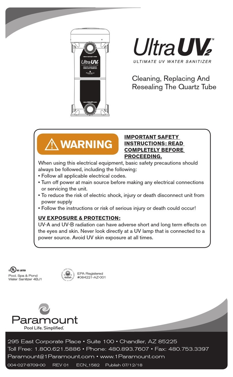
Paramount Fitness Ultra UV2 Guide

IMPORTANT SAFETY INSTRUCTIONS: READ COMPLETELY
BEFORE PROCEEDING.
When using this electrical equipment, basic safety precautions should always be followed, including the following:
WARNING:
• Follow all applicable electrical codes.
• Turn off power at main source before making any electrical connections or servicing the unit.
• To reduce the risk of electric shock, injury or death disconnect unit from power supply
• Follow the instructions or risk of serious injury or death could occur!
295 East Corporate Place • Suite 100 • Chandler, AZ 85225
Toll Free: 1.800.621.5886 • Phone: 480.893.7607 • Fax: 480.753.3397
004-027-8707-00 REV 01 ECN 1685 Publish date 01/30/19
Pool, Spa & Pond
Water Sanitizer 4BJ1
EPA Registered
#084221-AZ-001
Tank Replacement Instructions
DANGER indicates a
hazardous situation which, if not
avoided, will result in death or serious injury.
PLEASE REVIEW THE INSTALLATION GUIDE IN ITS ENTIRETY AND HEED ALL SAFETY
INFORMATION. Failure to follow these instructions and warnings can result in DEATH OR SERIOUS
INJURY.
DANGER
CAUTION indicates a hazardous
situation which, if not avoided,
could result in minor or moderate injury.
WARNING indicates a hazardous
situation which, if not avoided, could
result in death or serious injury.
NOTICE is used to address
practices not related to
physical injury.
WARNING
CAUTION NOTICE
Signal Words and Symbols Used In This Manual
This installation guide contains specific precautions and symbols to identify safety-related information. You
will find DANGER, CAUTION, WARNING and NOTICE symbols which require special attention. Please
read them carefully and follow these precautions as indicated! They will explain how to avoid hazards that
may endanger you or persons using or maintaining your pool or spa.
DANGER
UV EXPOSURE & PROTECTION:
UV-A and UV-B radiation can have adverse short and long term effects on the
eyes and skin. Never look directly at a UV lamp that is connected to a power source. Avoid UV skin
exposure at all times.
WARNING

2
IMPORTANT NOTES
The Ultra UV2 replacement tank is assembled with pressure switch, mounting plate, quartz tube, main
seal, compression washer & sealing nut. All replacement tanks are pressure tested at the factory.
The Ultra UV2 tank also includes ballast input wires for several build configurations.
Not all wires included in kit will be used.
On 230V units the existing conduit & power supply wires may be too short and need to be
replaced.
INSTALL THE REPLACEMENT TANK
1. Remove the three bonnet screws & lift bonnet
from old tank. The bonnet, screws, and
washers will be used for the new tank.
2. Disconnect the grounding wire from the
bonding lug.
3. Loosen the plumbing unions (two unions for
1-lamp & 2-lamp builds, and four unions for
3-lamp builds).
4. Remove the old Ultra UV2 unit from the
mounting location and set carefully aside.
NOTE: If in operating condition, the ballast &
lamps from the old unit will be re-installed.
5. Using ABS cement, install the supplied
blanking plugs & unions to the new
replacement tank.
• Be sure to match the placement of fittings
on the old tank.
• Note the orientation of the incoming
electrical supply.
6. Place the new replacement tank at the
mounting location.
7. Tighten the unions securely (do not over-
tighten).
8. Reconnect the grounding wire to the bonding lug.
Allow the ABS cement to cure
for a minimum of one hour.
CAUTION
Do not stand over the unit when
it is under pressure or when the
pump is on.
CAUTION
9. Turn on power to the pool pump and verify no
leaks are found at the new tank.
Turn off power to the pool
pump before proceeding
DANGER
Turn off the power supply to the old Ultra UV2 unit. Turn off power to the pool pump.
Disconnect the input power to the installed Ultra UV2:
• For 120v units unplug the supply cord from the GFCI.
• For 230v units disconnect the incoming power wires & conduit.
DANGER
Bonding Lug
Do not touch the glass part
of the lamp or quartz tube
with bare hands as body oils
will create hot spots & greatly shorten lamp life.
Always wear gloves.
NOTICE

3
Before removing lamps you must wear protective rubber gloves and safety eye wear.
Do not handle a hot lamp or serious burns will occur.
WARNING
Remove
retaining clip
Metal disk
ULTRA UV CONFIGURATION 1
1. It has a flat yellow disk mounted in the
center of the aluminum nut.
3. Disconnect all lamps by pressing the
release tabs on connectors and gently
pulling apart.
5. Remove metal disk from the old quartz tube
and place it gently into the new quartz tube.
Note: Dropping metal disk into quartz tube
may cause damage.
6. Install the lamps into the quartz tube in
the new tank.
4. Carefully lift the old lamp assembly from
the quartz tube. Set aside the lamp
assembly in a safe area to avoid breaking.
2. Squeeze the ends of the retaining clip to
remove or if disk is secured with silicone
gently pry the disk loose.
ULTRA UV CONFIGURATION 1 ULTRA UV CONFIGURATION 2 (see page 4)
IDENTIFY YOUR ULTRA UV2 UNIT AND FOLLOW INSTRUCTIONS ACCORDINGLY

4
ULTRA UV2 CONFIGURATION 2
INSTALLING BALLAST(S) TO NEW TANK
Remove
retaining clip
1. The lamp array is held in place by an
aluminum cup.
1. Using the supplied connector tool
disconnect the green, white and black
wires from the ballast by inserting the
tool in the slot next to the wire and pull
gently until wire is disconnected.
2. Remove ballast(s) from the old tank and
install onto the integrated brackets on
the new tank with the wire input side
facing the pressure switch.
3. Disconnect all lamps by pressing the
release tabs on connectors and gently
pulling apart.
4. Carefully lift the lamp assembly from the
quartz tube by the aluminum cup and not
the wires. Place lamps into new tank and
secure with retaining clip.
2. Squeeze the ends of the retaining clip
to remove.

5
Connect the color wires to the corresponding
color inputs in the ballast.
You will need to use some of the additional
wires included with the kit.
1. Remove the pre-wired single white wire (E)
from the left side of the terminal block.
2. Install the supplied double white wire (A)
to the terminal block. Tuck wires behind
terminal block.
4. Using one of the green ground wires (D),
connect it to the right ground post. Make
sure the flat washer is underneath the ring
terminal of the green wire.
5. Connect all the color wires to the
corresponding color inputs in the ballasts.
3. Remove the short black wire (C) from the
pressure switch. Install the supplied “Y”
connector (B) to the pressure switch, then
connect both supplied short black wires (C)
to the “Y” connector.
AE
B
C
F
D
D
C
SINGLE BALLAST WIRING
TWO BALLASTS WIRING

6
CONNECTING ULTRA UV2 UNIT TO POWER SOURCE
FOR 120V CORDED UNITS
1. Reinstall the Bonnet.
2. Connect the corded plug into the previously used GFCI receptible.
3. Power on the pump and ensure the system is functional.
• If not functional test the unit per a typical warranty call.
1. Install the conduit into the seal-tight connector.
Replace the conduit if it is too short. Lift the
grommet from the mounting plate and feed the
two power wires & and ground wire. Replace
wires if any are too short. Use the supplied
tube of silicone and cover the wires at the
junction of the conduit connector. Reinstall
the grommet to the mounting plate.
3. Cut the ground wire to length and attach
an 18-22 AWG ring terminal. Remove
the nut from the left ground post. Place
the ring terminal over the ground post.
Reattach the nut.
4. Reinstall the Bonnet.
5. Turn on the breaker for the Ultra UV2 unit.
6. Power on the pump and ensure the system
is functional.
• If not functional test the unit per a typical
warranty call.
2. Attach one power leg (most likely black) to
the upper right position of the terminal block.
Attach one power leg (most likely white) to
the lower right position of the terminal block.
• NOTE: The terminal block is sized to
accept a spade terminal for 18-22AWG
wire.
FOR 230V HARD-WIRED UNITS

7
Paramount Part# Description
1005-422-3100-00 Ultra UV Tank Replacement - 230V
Includes: Wires, “Y” connector, quartz tube, quartz tube o-ring, compression
washer, 2" union kit, (6) blanking plugs
2005-422-3000-00 Ultra UV Tank Replacement - 120V
Includes: Wires, “Y” connector, quartz tube, quartz tube o-ring, compression
washer, 2” union kit, (6) blanking plugs
ULTRA UV TANK REPLACEMENT PART NUMBERS
1 2

8
Other manuals for Ultra UV2
5
Table of contents
Other Paramount Fitness Accessories manuals

Paramount Fitness
Paramount Fitness Ultra UV 004-422-2025-00 User manual

Paramount Fitness
Paramount Fitness Ultra UV User manual

Paramount Fitness
Paramount Fitness Ultra UV2 User manual

Paramount Fitness
Paramount Fitness Ultra UV2 Guide

Paramount Fitness
Paramount Fitness Ultra UV2 Operating and safety instructions

Paramount Fitness
Paramount Fitness UltraUV User manual