WARNING
NOWN DROWNING HAZARD.
DO NOT GO NEAR THE SUCTION FITTINGS OR DRAINS OF YOUR POOL OR SPA. YOUR HAIR OR BODY
MAY BECOME TRAPPED CAUSING PERMANENT INJURY OR DROWNING.
DO NOT ENTER THE POOL OR SPA IF SUCTION FITTINGS OR DRAIN COVERS ARE LOOSE, BRO EN, OR MISSING.
WARNING
RIS OF SEVERE INJURY OR DROWNING IF SUCTION SYSTEMS ARE NOT INSTALLED PROPERLY!
NOTICE TO OWNER:
READ, FOLLOW, AND SAVE THESE SAFETY INSTRUCTIONS.
© 2003, Paramount Pool & Spa Systems
Suction can pose a serious hazard to swimmers just as electricity can be a hazard. Both are important for proper water
filtration and both must be treated with respect. Suction safety begins with a professional design that includes a quality
suction system installed by a certified contractor.
The MDX Debris Removal System is only available to certified contractors for the same reason certified electricians
are required to connect filtration pumps to public utilities; both require proper training and certification to assure no
hidden hazards are built into the project.
Certified builders will address the following issues when designing and installing a proper filtration system:
• Properly bond-grounded pumps, time clocks, switches and any other metal in or near water. This is required to
address Electrical Shock Hazards.
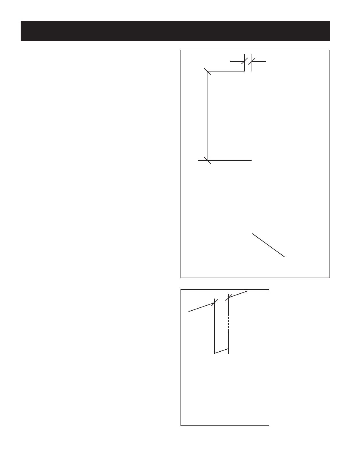
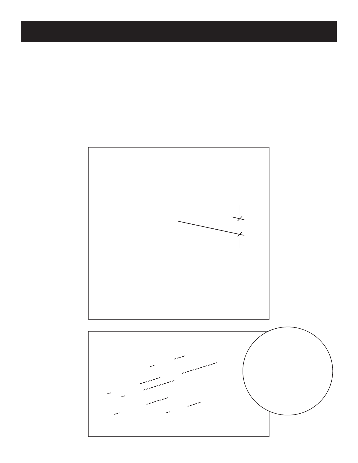
• Design the suction piping so there are no single-point suction hazards; single-point suction (one drain) is a leading
cause of Body Suction Entrapment Hazards. Note: your certified builder has many effective options for addressing
this hazard; they may include dual-drain systems, like MDX, skimmers, gutters, negative edge features and many
more products and piping designs known to professionals.
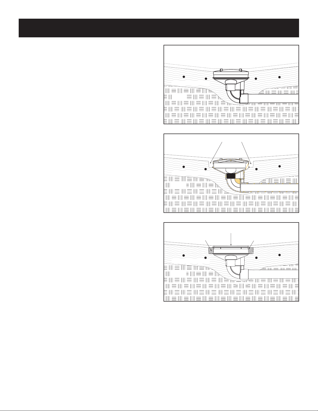
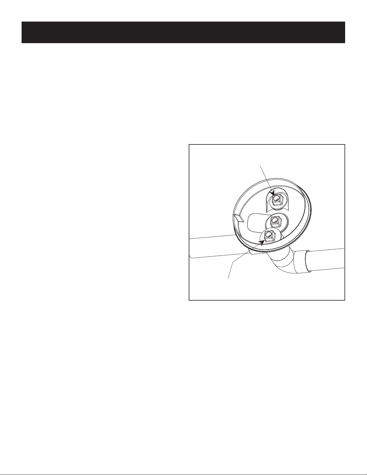
• Install AASSMMEE//AANNSSII AA111122..1199..88MMlisted drains, suction covers and debris removal systems. This is the OONNLLYY
approved option for preventing Hair Entrapment Hazards, the leading cause of suction related injuries.
• Design and install an effective circulation system (including optional cleaning systems), to direct filtered water to
all areas and interior surfaces. NOTE: Suction fittings can NOT clean or direct filtered water for proper sanitation;
that can only be done on the pressure (return) side of the filtration system.
While suction injuries are extremely rare, drowning and diving injuries are far too common and there is little your
certified builder can do to eliminate these hazards. You must educate yourself and your guests. Below are some
important safety issues every swimmer must know and recognize.
•PPRREEVVEENNTT DDRROOWWNNIINN::Watch children at all times, no swimming alone.
•NNOO DDIIVVIINN IINN SSHHAALLLLOOWW WWAATTEERR::You can be permanently injured.
•PPRREEVVEENNTT SSUUCCTTIIOONN EENNTTRRAAPPMMEENNTT::Inspect suction covers before swimming, keep swimmers away from suction
fittings, protect long hair, don’t swim with loose clothing or large and dangling jewelry.
IMPORTANT NOTICES: PLEASE READ