Park Flite Super Cub PA-18 User manual


2
Piper Super Cub PA18
INSTRUCTION MANUAL
CONGRATULATIONS ON PURCHASING THE SUPER CUB RTF
Top Gun Park-Flite are proud to present this high performance sport scale model of the popular Super Cub.
We feel that this model emulates the style, performance and character of its full size counterpart.
Supplied as a Ready to Fly package with transmitter, LiPo flight battery and charger, this model has been
designed with the utmost care and attention to detail to produce a light weight, strong, and realistic looking
model aeroplane with excellent flying characteristics.
This model is a high performance miniature aircraft that allows novice to intermediate model pilots to
perform both scale and aerobatic manoeuvers. The light weight, large wing area and high wing design allow
the model to fly extremely slowly, in a stable manner while still maintaining full control.
These instructions assume a reasonable level of competence for both building and flying and we
recommend that the model is flown at a recognised club with frequency control measures and suitable third
party insurance.
The owner – pilot of this model should take note of regulations, and local bylaws before flying this aircraft.
Please take time to read through these instructions before commencing assembly. We list operations in
order of works to reduce the risk of damage during assembly.
RTF MODEL

3
WARNING
This R/C aircraft is not a toy and can result in serious
bodily harm, injury and property damage if misused.
Fly only in open areas and at preferably BMFA recognised
clubs and sites.
SPECIFICATIONS
WING SPAN: 1060 MM (42”)
LENGTH: 710 MM (28”)
WING AREA: 17 DM_ (264 SQ INCHES)
WEIGHT: 540 G (19 OUNCES)
RADIO: 4 FUNCTION 35MHZ PPM
3 QTY MICRO SERVOS
25 AMP BRUSHLESS ESC
MOTOR: BRUSHLESS OUT RUNNER
9” X 5” PROPELLOR
11.1V 1250MAH LIPO BATTERY
PLEASE READ
THROUGH THE
WARNINGS BEFORE
USE.
An 11.1V 1250 mAh lithium
polymer (LiPo) battery rated at
10C and charger is included as
part of this package and these
cells must be operated with care
to prevent the risk of fire.
LiPo Batteries are soft cased and
can be easily damaged by sharp
items, puncturing of the soft
casing can cause fires and we
recommend that they are stored
and handled carefully.
Use only a LiPo rated charger, set
to a maximum of 3 cells (11.1v)
and 1 amp charge current.
Remove battery from the aircraft
and charge on a non flammable,
non conductive surface
Due to continual and ongoing
product development the parts
shown in the manual may differ
from those supplied.

4
1. Wing with ailerons connected to factory
installed servos
2. Fuselage with motor, Electronic Speed Control
(ESC) receiver, two quantity servo, and pushrods.
3. Fin and rudder assembly
4. Horizontal stabiliser (Tail plane) with elevator
5. Main undercarriage assembly mounting plate
and wheels
6. 4 function fully proportional 35Mhz transmitter
7. Control horns and back plates for elevator and
rudder
8. Tube of adhesive
9. LiPo Battery 3cell 11.1V 1250 mAh (10c)
10. LiPo charger and 12v power lead
11. Propellor – 2 off 9” diameter x 5” pitch with
spinner
12. Self adhesive decal sheet.
SECTION 1: KIT CONTENTS AND DESCRIPTION

5
FUSELAGE ASSEMBLY.
Supplied complete and ready for
use. Brushless motor installed
and connected to Electronic
Speed Control (ESC), 35mhz
receiver, rudder, elevator servos
connected to push rods
WING ASSEMBLY.
Supplied complete and ready to
fit with hinged wing struts,
aileron servo, push rods bell
cranks and control horns
installed.
VERTICAL AND HORIZONTAL
STABILISERS
Vertical Stabiliser (Fin and
rudder) with moulded in hinges.
Horizontal Stabiliser (tail plane
and elevator) with moulded in
hinges.
UNDERCARRIAGE
ASSEMBLY,
Ready for use, with mounting
plate and wheels.
Tail wheel is pre fitted to fin.

6
BATTERY AND CHARGER
11.1V (3 cell) 1250mAh LiPo
Battery rated at 10C max
discharge.
12v DC input 0.8 to 1A output
balancing type fast charger
12v crocodile clip connecting
lead.
CONTROL HORNS
Control horns with clamp
connectors and back plates 2 off.
One each for elevator and rudder
PROPELLOR
2 off E-Pro 9” diameter x 5” pitch
moulded propellors.
Ensure text is on front face when
mounting.
ADHESIVE
5ml tube of foam safe adhesive.
Note pierce end of tube with pin
in screw on lid.

7
SECTION 2: BATTERY AND CHARGER WARNING!
A lithium polymer (LiPo) battery rated at 10C
and charger is included as part of this package
and these cells must be operated with care to
prevent the risk of fire.
LiPo Batteries are soft cased and can be easily
damaged by sharp items, puncturing of the soft
casing can cause fires and we recommend that
they are stored and handled carefully.
Use only a LiPo rated charger, set to a
maximum of 3 cells (11.1v) and 1 amp charge
current.
Remove battery from the aircraft and charge on
a non flammable, non conductive surface.
BATTERY AND CHARGER
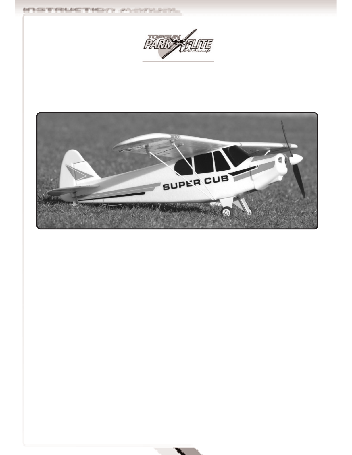
The Skylane includes a high performance 11.1V (3
cell) 1250mAh LiPo Battery rated at 10C max
discharge.
This must be charged using the dedicated 12v DC
input 0.8 to 1A output fast charger and connecting
lead
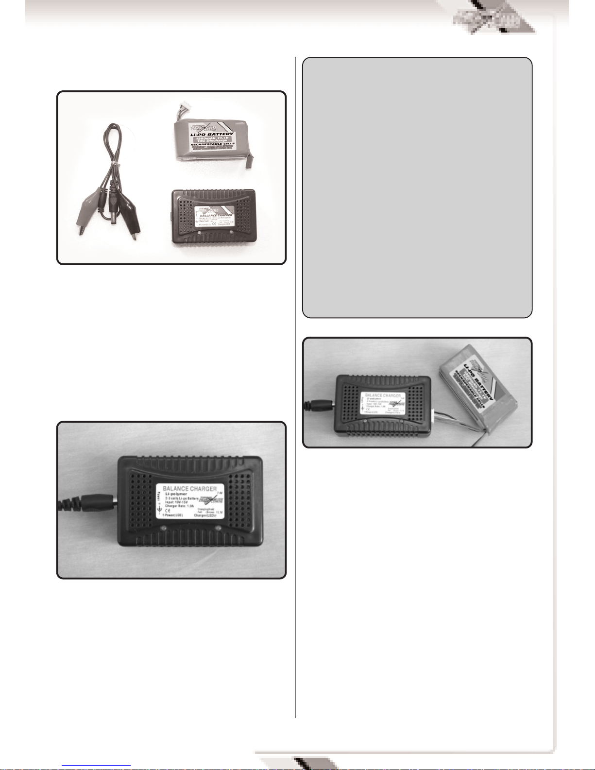
Connect the crocodile lead connectors to a 12V DC
power source (a 12V car battery is ideal), ensuring
that correct polarity is observed. Red is positive (+)
and Black is Negative (-).
Connect the lead into the battery charger. The power
light will illuminate and all three LED,s will flash as
a system check.
Push the white balance plug of the battery into the
11.1v charger output socket to commence charging.
The Indicator light changes from amber to green
when the charge is complete
A full charge will take between 1 and 2 hours.

8
Locate the horizontal stabiliser and fuselage.
Apply adhesive into the tail plane seat and insert
the horizontal stabiliser.
Check that stabiliser is central, level and square to
the fuselage.
Use a damp cloth to wipe off excess adhesive and
allow to dry.
SECTION 3: ASSEMBLY
Locate the preformed undercarriage assembly.
Position over recess on underside of fuselage with
tapered edge of spats facing aft.
Push undercarriage mounting plate in position and
fix in place with four self tapping screws.
Locate the fin & rudder assembly.
Apply adhesive to the fin and insert in to the
fuselage and horizontal stabiliser. Apply adhesive
to the hinge tab that extends infront of the rear
tailwheel.
The notch in the fin locates with the hole in the
stabiliser.
Check that fin is vertical and square to the tail
plane and press firmly in place.
Use a damp cloth to wipe off excess adhesive.
Allow to dry.
Locate control horn and clamp connectors for
rudder and elevator.

9
Slide pushrod wires through clamp connectors.
Push control horn pins through holes in control
surface.
Apply a spot of adhesive to the control horn and its
backplate before pushing tight to surface and fitting
backplate.
Apply a spot of adhesive to the clamp connector
fixing nut to ensure it does not come loose.
Use a damp cloth to wipe off excess adhesive and
allow to dry.
The Suplex 4 is a fully proportional 4 function
35Mhz transmitter
The transmitter is supplied in a Mode 2
configuration.
Mode 2 is also known as Throttle Left.
The left stick controls Throttle and rudder
movement.
The right stick controls aileron and elevator
movement.
Battery state is indicated by a bank of coloured
LED’s. With green for full and red for empty.
As soon as the indicator changes to amber the
model should be landed to allow battery
replacement.
A red LED indicates dangerously low voltage. The
model should be landed immediately to replace
batteries before all control is lost.Construction of the Piper PA-18 is now complete
and the following steps can be considered as part
of the daily assembly and rigging of the model.
Fix propellor to prop shaft using the M3 aluminium
spinner nut.
Note that washers are fitted to both sides of the
propellor.
The text on the propellor faces forward.
Push the spinner firmly in place.
SECTION 4: TRANSMITTER

10
Frequency control is by removable crystal
The transmitter frequency is identified on the
crystal holder located at the rear of the transmitter.
8 off AA size dry cells or high capacity Nimh
batteries must be inserted before operation.
Remove the rear cover and install batteries into the
battery tray as directed by the moulded in polarity
(+ & -) markings.
A small panel of four small slide switches is set on
the front panel of the transmitter.
These are electronic servo reversing switches and
should be adjusted to give the correct control
surface deflections relative to stick movements.
SECTION 5: FINAL SET UP
Locate the wing assembly and position it over the
wing seating area with the servo on the underside.
Take the plug on the aileron servo lead and push
plug into channel no 1 of the receiver.
Note that black is (-) Negative and orange is signal.
Push the wing firmly down onto its seat until wing
leading edge pegs locate into mounting plate.
Ensure that aileron wire is inside fuselage
The wing retaining latch should be pulled back to
allow the trailing edge to locate in the fuselage and
will click in position when the wing is correctly
seated.
Ensure that the wing struts are to the bottom of the
fuselage and fix in place with small screws.
The struts must be fitted to ensure safe flight.

11
Apply a wrap of adhesive tape around the battery to
use as a pull handle for removal and insert into the
forward battery box.
Ensure that battery and ESC leads project out of the
aperture.
Connect the battery and ESC leads together and fit
the battery cover in place.
The tongue locates in a slot and the screw fixes into
a wooden plate below the foam.
Uncoil the receiver aerial and fully extend to hang
off the rear of the aircraft.
WARNING!
With the battery connected and the model
switched on the motor is now live. The
Electronic speed controller (ESC) will go
through its start up procedure and will emit a
series of beeps while it configures throttle
positions. The motor could start unexpectedly
and we recommend that the model is
restrained and that the operator keeps clear of
the propellor during handling.
Check that all controls operate in the correct
manner and that surfaces for aileron, elevator and
rudder are level.
Adjust if required by loosening clamp connectors
using a Phillips head screwdriver, adjust pushrod
locations until surfaces are level and then tighten
clamp connectors.
Move transmitter sticks to ensure free movement of
the control surfaces.

12
CHECK THE BALANCE.
The model should sit level or slightly nose down
when supported off a point 50 to 54mm from the
wing leading edge.
DO NOT ATTEMPT TO FLY WITH A REARWARD
BALANCE POINT FLYING
The Super Cub is easily capable of 15 to 20 minute
flight times and can R.O.G (Rise Off Ground) from
smooth closely cut grass runways. It is aerobatic
and able to perform loops, rolls, and stall turns.
Due to its light weight it should not be flown in wind
greater than 10mph.
The use of rudder co-ordinated with aileron input
will produce smooth and scale like turns.
Control throws set during assembly will produce a
model capable of flying smooth scale like
performance and medium to high speed aerobatic
manoeuvers.
The control surface movements can be increased by
moving the clamp connectors nearer to the control
surfaces.
To reduce movements move the pushrod
connections nearer to the servo on the output arms
and further out along the control surfaces horns.
ENJOY YOURSELF BUT ALWAYS FLY SAFE!
BEFORE THE TEST FLIGHT
On completion of the model take time to test rig the
model in the workshop several times.
Connect radio gear and double check that all
surfaces operate in the correct manner without
stalled servos.
Check for adequate range with and without motor
running.
If everything is okay, take it to the flying field and
rig it up again.
Always follow the frequency control procedures of
your local flying site and ensure that you have
adequate third party insurance cover.
Repeat the full pre flight inspection before flying.
50 to 54mm
SECTION 6: FIRST FLIGHT
WARNING!
Do not advance the throttle unless the model is
restrained. With the powerful motor propellor
combination, the model will accelerate across a
smooth surface very quickly.

13
NOTES:

14

15
When I run the program it doesn’t work or I
get no mouse cursor. I get a blank or funny
screen or am experiencing graphical
glitches.
Update your graphics drivers from your
manufacturers website. If you have a GeForce
card go to;
http://www.nvidia.comor if you have an ATI
card go to www.ati.com
If you have a different one then you will need to
find your manufacturers website.
Make sure you install the driver properly.
You must click ‘Continue Anyway’ when or if
Windows throws you a warning. This is
normal.
You may also need to update your motherboard
drivers from your chipset manufacturer. e.g.
VIA at www.viaarena.com, Intel, etc. You will
need
to find out who the manufacturer of your
motherboard is. Ask your computer
manufacturer or right click on ‘My Computer’ ->
‘Properties’ -> ‘Hardware’ tab -
> ‘Device Manager’ -> ‘System Devices’. The
manufacturer should be labelled as the AGP
or PCI make.
When I use my controller it moves
erratically.
Recalibrate the controller. Go to the controller
menu and select your controller.
Then click Re-calibrate. Follow the instructions
as they appear. For more information on setting
up your controller check out the relevant
section in the manual.
The controls move in the wrong direction.
Go to the controller menu and click on the
toggle switch to reverse the channel on the axis
concerned. For more information on setting up
your controller check out the relevant section in
the manual.
Do I have to put the CD in every time I run
the program?
Yes. It is very common practice for
entertainment/multimedia software.
The alternative is to force people to buy high
cost hardware (i.e. USB controller/interface)
with the software.
FAQ’S

TGP0125 Fuselage
TGP0126 Main Wing
TGP0127 Cowl
TGP0128 Landing Gear
TGP0129 Elevator
TGP0130 Rudder
TGP0131 Wing Struts
TGP0132 Propellers
TGP0133 Super Cub EP Decal
TGP0531 Bell Outrunner Brushless motor
TGE0051 Top Gun E-Tronix Brushless 25 amp
TGP0600 Control Horns
TGP0601 Quick Link Colla
TGE1000 Top Gun Etronix 8.4g servo
TGP0510 Suplex 4 4ch transmitter
TGP0516 Top Gun Park-Flite Lipo 12v Charger
TGP0517 Adapter for li-po charger
TGP0522 Lipo 11.1v 1250mAh 10c Cells
DISTRIBUTORS OF QUALITY MODEL & HOBBY PRODUCTS
Saxon House, Saxon Business Park, Hanbury Road, Bromsgrove, Worcestershire. B60 4AD. England
Tel: +44 (0) 1527 575349 Fax: + 44 (0) 1527 570536
E-mail: [email protected]
Web site: www.cmldistribution.co.uk
TOP GUN PARK FLITE PIPER PA-18 SUPER CUB SPARE PARTS LIST
Table of contents
Other Park Flite Toy manuals
Popular Toy manuals by other brands

KDE Direct
KDE Direct Align Trex 550 Series quick start guide

REVELL
REVELL BURST user manual

Dynaflite
Dynaflite butterfly instruction manual

REVELL
REVELL German Heavy Cruiser Blucher Assembly manual

LEGO
LEGO 60135 Assembly instruction

Fisher-Price
Fisher-Price SUPER TALK! 76960 Owner's manual & assembly instructions