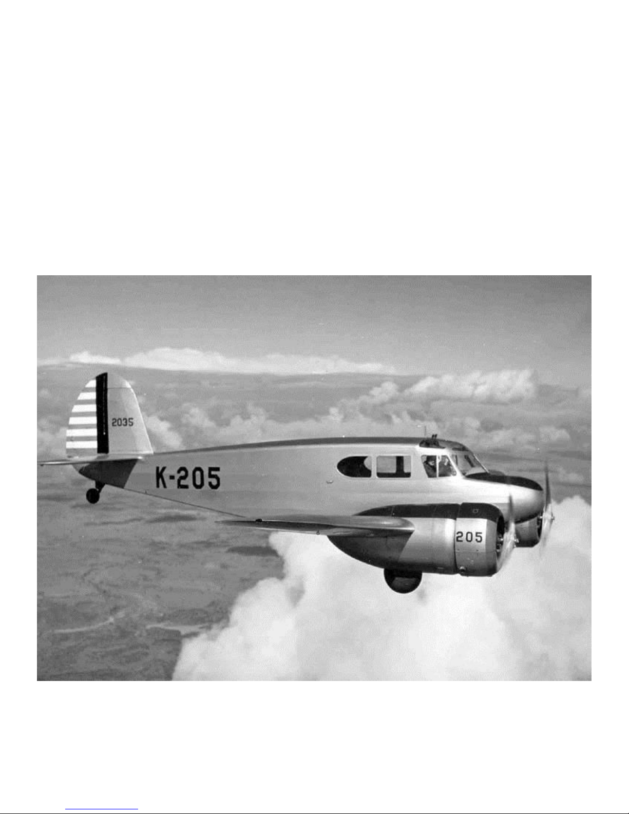
Park Scale Models AT-17 Bobcat User manual

Park Scale Models
AT-17 Bobcat
Assembly Manual

Fuselage Construction
1. Glue the two ¼” balsa servo rails SR to BB5.
2. Assemble the wing mount block by gluing
WM1(x2), WM2 and WM3 together as shown.
3. Epoxy two of the supplied nylon nuts into the
wing mount block as shown. Be very careful not
to get any epoxy into the threads of the nut.
BB5
SR
5
WM3
WM2
WM1

4. Assemble the servo tray by gluing BB5 to BB7 as
shown. Ensure that BB5 is perpendicular to BB7.
5. Fit and glue the servo try assembly to BB3.
6. Fit and glue BB1 to BB3 Fit and glue the wing
mount block to BB3 and BB7.
7. Fit and glue BB2 to BB1, BB5, BB& and the wing
mount block.
BB5
BB7
BB3
BB1
Wing mount
block
BB2

8. Fit and glue BB4 to BB2 & BB3. Fit and glue BB6 to
BB2, BB3, BB5 and the wing mount block. It is
recommended to install your rudder and elevator
servos into the servo tray at this time.
9. Fit and glue FL7A (x2) to F3.
10. Fit and glue F2 to FL7A.
11. Fit and glue FL4(x2), FL5(x2) and FL6(x2) to F2 &
F3.
BB6
BB4
FL7A
F3
F2
FL4
FL5
FL6

12. Fit and glue FL10 into the center notches of F2 &
F3. Fit and glue FL9, FL8 and FL7 into the notches
in F2 & F3 on both sides of FL10.
13. Slide this assembly onto the wing mount/battery
box assembly as shown, do not glue in place!
14. Fit and glue FL1 into the center notch of F3,
unsure that the notch in FL1 is facing up. Fit and
glue FL2 and FL3 on both sides of FL1 as shown.
15. Fit and glue F1 to the wing mount/battery tray
assembly first. Carefully align and fit FL1-FL10 into
the notches in F1, ensure that they are fully
inserted into the notches and then glue in place.
Glue F2 and F3 to the wing mount/battery box
assembly.
FL10
FL9
FL8
FL7
FL1
FL2
FL3
F1

16. Assemble formers F4 and F5. Glue F6 to the motor
mount assembly. Fit and glue F4 and F5 into the
notches in the wing mount assembly. Glue F4 to
F3 and the wing mount assembly. Glue F5 to the
top of the wing mount assembly only!
See the end of the manual for how to assemble
the fuselage formers.
17. Assemble the fuselage sides as shown below. Fit
and glue the fuselage sides to F4-F6.
18. Fit formers F7-F9 into the fuselage sides.
19. Fit and glue F10 and F12A to the fuselage sides.
Ensure that the fuselage is straight before gluing
the formers F7-F9 in place.

20. Fit and glue F12 to F10 and the fuselage sides.
21. Fit and glue F11 to F12, F12A and the fuselage
sides.
22. Epoxy F11A to F11, F12A and the fuselage sides.
23. If you plan to install a steerable tail wheel it is
recommended to use a Dubro 1/2A steerable nose
wheel. Screw the mount to F11 using the pre-
drilled holes in F11. You will need to install the
control linkage to connect the tail wheel to the
rudder servo.
If you do not wish to install a steerable tail wheel,
a fixed tail wheel can be installed later.

24. Install the rudder and elevator pushrod sleeves.
Use Dubro Lazer Pushrods or similar.
25. Fit and glue F12B in place.
26. Fit and glue FS4 to F6-F10. Glue two pieces of
3/16” sq. balsa sticks into the notches in the
bottom of F6-F10 and also to the fuselage sides.
27. Glue two pieces of 3/16” sq. balsa sticks into the
notches in the top of F4-F10 and also to the
fuselage sides.
FS4

28. Fit and glue FS1A to F4-F6. Fit and glue FS2A to F4-
F8. Fit and glue FS1B to F6-F10. Fit and glue FS2B
to F8-F10. Fit and glue FS3 to F4-F8.
cop
29. Glue SH2(x2) in place where indicated, lightly
dampen the outside surface to help bending if
necessary. Fit and glue SH1 in place.
30. Glue SH3(x2) in place where indicated, lightly
dampen the outside surface to help bending if
necessary.
31. Fit and glue B1-B16 in place. Start with B12 and
work forward to B1.
FS1
FS2
FS3
SH1
SH2
B1
B16

Wing Construction
1. Start the center wing section by fitting R1(x2) and
R2(x2) to WS1A and WS2A. Ensure that the ribs
are perpendicular to the spars before gluing.
2. Fit and glue WS3, WM5 and TE1 to ribs.
3. Cut two (2) 5” lengths of the supplied 3/16”
hardwood dowel. Insert the dowels into the wing
spars as shown and epoxy in place. Allow the
dowels to extend past WS3 by ¼”.
R1
R2
WS2A
WS1A
WM5
TE1
WS3

4. Fit and glue WL1 and WL2 in place.
5. Sheet the bottom of the center wing section with
1/16” balsa.
6. Cut the electronics tray from some scrap wood
using the template at the end of the manual. Glue
to WS1A, WS2A and R1(x2).
7. Sand TE1 to match the contour of the ribs. Sheet
the top of the wing center section with 1/16”
balsa. Cut out the sheeting around the electronics
tray area.
WL2
WL1

8. Cut the leading edge sheeting from1/16” balsa to
size using the measurements below, ensure the
long edge is straight. Glue WS1 on top of the 1/16”
balsa sheet along the straight edge.
9. Cut a sheet of 1/16” balsa to size using the
measurements below. Edge glue to the leading
edge sheeting.
10. Fit ribs R5-R14 to the spar, do not glue yet.
11. Fit and glue SDF between R7 and R8, ensure it is
tight up against the wing spar. Fit and glue the
1/16” balsa servo door sheeting between ribs R10
and R11, ensure it is tight up against the wing
spar.
2.5”
22.75”
3.75”
7.25”
11”
8.75”
straight edge
glue on top of sheet
straight edge
SDF
servo door sheeting
WS1

12. Fit and glue SDF between R10 and R11, ensure it is
tight up against the wing spar. Trim any
overhanging balsa sheeting flush with R8.
13. Fit and glue TE2 to R5-R9 and the balsa sheeting.
Glue R5-R7 to the balsa sheeting.
14. Fit and glue R9A to the outside R9 and TE2.
15. Fit and glue TE3 to R9A –R14.
trim sheeting flush with R8
SDF
TE2
R9A

16. Fit WS2, S1B and S2B in place where shown. Do
not glue in place yet.
17. Fit R3 and R4 in place where shown. Ensure that
all parts are fit together tightly and then glue R3
and R4 to WS1, WS2, S1B, S2B and the balsa
sheeting. Glue S1B to WS1 and the sheeting. Glue
S2B to WS2 and the sheeting. Remove any excess
glue at the joints between S1B/WS1 and S2B/WS2.
18. Fit and glue S1A to WS1 and R3-R5. Fit and glue
S2A to WS1 and R3-R5. Fit and glue TE1 to R3, R4
and the sheeting. Remove any excess glue at the
joints between S1A/WS1 and S2A/WS2.
19. Fit and glue the 1/32” plywood shearwebs to
S1A/B and S2A/B. Epoxy shearwebs to R3, R4 and
the balsa sheeting.
S1B
WS2
S2B
R4
R3
S1A
1/32” ply
shearweb
TE2A

20. Fit R3A in place.
21. Fit and glue LE1 to R3A-R14. Sand LE1 to match
the top and bottom contours of the wing ribs.
22. Trim the excess sheeting along R3.
23. Glue the bottom sheeting to R3-R14 and LE1.
LE1

24. Fit and glue some 1/16” balsa sheeting to the
bottom of R13 and R14.
25. Sheet the top of the wing as shown with 1/16”
balsa.
26. Trim away the excess sheeting along LE2 and R4 as
shown.
27. Fit and glue TE2A to TE2 and TE3A to TE3. Use
hinges to ensure that the hinge slots line up
properly.
TE2A
TE3A

28. Sand the sheeting flush with LE1 and then glue
some 1/8” balsa to the leading edge of the wing
and sand to shape.
29. Align and glue F15 to F14.
30. Fit and glue WTS into the slot in F15.
31. Fit and glue WT to F15 and WTS as shown.

32. Cut away the leading edge sheeting between R5
and R6. DO NOT cut through the spar!
33. Epoxy two FW1 together and glue to nacelle frame
NF1 as shown. Fit RB1 (blue) and RB2 (red) into
NF1, do not glue yet.
34. Fit and glue FW2 to NF1 and FW1.
35. Fit NF2 in place as shown. Check that RB1 and RB2
align properly and fit into the slots as shown.
Remove NF2, epoxy RB1 & RB2 together. Fit and
glue NF2 to FW1 & FW2. Epoxy RB1/RB2 to FW1
and FW2.
RB2 (red)
RB1 (blue)
FW1 (x2)
FW2
NF2

36. Fit your retracts to RB1/RB2. Use the template
supplied by your retract manufacturer to cut the
opening for your retracts.
37. Fit and glue NF1A, NF1B, NF1C & NF1D together.
38. Fit NF1 and NF3A in place where shown, do not
glue yet.
39. Fit and glue NF3B, NF3C & NF3D and NF4B, NF4C
& NF4D together.
NF1A
NF1
NF3A
NF1B
NF1C
NF1D
NF3C
NF3B
NF4B
NF4C
NF4D
NF3D

40. Fit NF3, NF4, NF5 & NF6 in place as shown. Do not
glue yet. Test fit the nacelle to the wing to ensure
the formers are oriented correctly. Remove
nacelle from wing and glue the formers in place.
41. Fit and glue NL1, NL2 & NL3 in place as shown.
42. Fit and glue NF2A, NF2B, NF2C & NF2D together.
43. Fit and glue NF2 in place as shown.
NF6
NF4
NF5
NF3
NL3
NL1
NL2
NF2
NF2A
NF2B
NF2C
NF2D
Table of contents
Other Park Scale Models Toy manuals

Park Scale Models
Park Scale Models Boeing 314 User manual

Park Scale Models
Park Scale Models NS-TKAT User manual

Park Scale Models
Park Scale Models Grumman HU-16 Albatross User manual

Park Scale Models
Park Scale Models Cessna 182 User manual

Park Scale Models
Park Scale Models Mini Drake User manual

Park Scale Models
Park Scale Models LoLo User manual
Popular Toy manuals by other brands

Mattel
Mattel Karmas World HHD13 quick start guide

Hokusei
Hokusei Primus EPP Assembly & operation manual

marklin
marklin 73407 user manual

Plum
Plum peppermint townhouse 41071 Assembly instructions

LEGO
LEGO 41150 manual

WARCRADLE STUDIOS
WARCRADLE STUDIOS DYSTOPIAN WARS CROWN SUPPORT SQUADRONS Assembly instructions