Parker EXACTOL 400 Series Manual

Parker 400 Series
Tube Benders
Bulletin 4391-B400S

Bulletin 4391-B400S EXACTOL®400 Series Tube Benders
Parker Hannifin Corporation
Tube Fittings Division
Columbus, OH
www.parker.com/tfd
FAILURE OR IMPROPER SELECTION OR IMPROPER USE OF THE PRODUCTS AND/OR SYSTEMS DESCRIBED HEREIN OR RELATED ITEMS CAN CAUSE DEATH, PERSONAL
INJURY AND PROPERTY DAMAGE.
This document and other information from Parker Hannifin Corporation, its subsidiaries and authorized distributors provide product and/or system options for further investigation by users
having technical expertise. It is important that you analyze all aspects of your application and review the information concerning the product or system in the current product catalog. Due
to the variety of operating conditions and applications for these products or systems, the user, through its own analysis and testing, is solely responsible for making the final selection of
the products and systems and assuring that all performance, safety and warning requirements of the application are met.
The products described herein, including without limitation, product features, specifications, designs, availability and pricing, are subject to change by Parker Hannifin Corporation and its
subsidiaries at any time without notice.
WARNING
The items described in this document are hereby offered for sale by Parker Hannifin Corporation, its subsidiaries or its authorized distributors. This offer and its acceptance are governed
by the provisions stated in the “Offer of Sale”.
Offer of Sale
Table of Contents
Table of Contents
Introduction.....................................................................1
Capacity and Specifications ...........................................1
Parts and Accessories....................................................2
Radius Blocks.................................................................3
Medium to Heavy Wall Tube Bending .......................4 – 5
Thin Wall Tube Bending with Mandrel Equipment ....6 – 8
Model 412 Parts Schematic............................................9
Model 424 Parts Schematic..........................................10
Bender Kits...................................................................11
Offer of Sale .................................................................13
Copyright 2016, Parker Hannifin Corporation, All Rights Reserved

Bulletin 4391-B400S EXACTOL®400 Series Tube Benders
1Parker Hannifin Corporation
Tube Fittings Division
Columbus, OH
www.parker.com/tfd
Introduction, Capacity and Specifications
EXACTOL®Tube
Benders
(For 1/4" – 1-1/2" diameter tubing)
Sturdy…Simple…Manual…
Bends to exact tolerances.
The Parker Exactol Tube Benders are probably the
most versatile bench benders available today. Built for
easy manual bending of copper, brass, aluminum, steel
and stainless steel tubes to exact tolerances, the 400
Series benders are also compact and portable to any
area for service use where a vise is available.
Along with the bender itself, Parker has developed a complete package of accessories to enable this tool to be
used for all types of bending: close bend radius blocks, mandrels for thin wall tubes, bench mounting adapters
and more.
Capacity
Tube
O.D.
(mm) Material
Tube Wall Thickness (mm)
1.5 2 2.5 3 3.5 4
Bender Code*
18 S AC AC AC AC C C
SS C C C C C C
20 S AC AC AC C C C
SS C C C C C C
22 S C C C C C C
SS C C C C C
25 S C C C C C
SS C C C C
28 S C C C C
SS C C
30 S C C C C
SS C C
32 S C C
SS C
38 S C
SS
*Codes: A Model 412 — Tubing (6mm through 20mm)
C Model 424 — Tubing (6mm through 38mm)
Specifications
Description Model 412 Model 424
Min. tube size 1/4” 1/4”
Max. tube size 3/4” 1-1/2”
Max. bend 180° 180°
Max. radius 3” 5”
Gear ratio 60:1 60:1
Weight (base unit) 14 lbs. 40 lbs.
Finish Natural Aluminum Natural Aluminum
Notes:
1. All benders are capable of bending 1/2” O.D. and under fully
annealed steel and stainless steel tubing with no limit on wall
thickness.
2. All benders are capable of bending soft aluminum and copper
tubing to the full range of each bender type capacity with no limit
on wall thickness.
3. For hard copper and high strength aluminum use the tabulations
shown for stainless steel. Observe that very hard materials may
not be ductile enough to bend without fracture.
Tube Benders Maximum Capacity Guides
Tube
O.D. Material
Tube Wall Thickness (Inches)
0.035 0.049 0.058 0.065 0.072 0.083 0.095 0.109 0.12 0.134 0.156 0.188
Bender Code*
3/4" S AC AC AC AC CCCCCCCC
SS AC AC CCCCCCCCCC
1" S CCCCCCCCCCCC
SS CCCCCCCCCC
1-1/4" S C C C C C C
SS C C C C C
1-1/2" S C C C C C
SS C C
*Codes:
A Model 412 – Tubing (1/4" thru
3/4") – Worm & Gear – Rated
Torque 2,700 in. lbs.
C Model 424 – Tubing (1/4" thru
1-1/2") – Worm & Gear – Rated
Torque 11,000 in. lbs.

Bulletin 4391-B400S EXACTOL®400 Series Tube Benders
2Parker Hannifin Corporation
Tube Fittings Division
Columbus, OH
www.parker.com/tfd
Parts and Accessories
Bender Parts and Accessories
Carrying Case
550572 (412 only)
Seal-Lok Close
Bend Adapter
Bench Mounting
Adapter
Handle
Slide Blocks
Typical Radius Blocks
Three Hole
Two Hole
Close Bend
EXACTOL Bender
Bender Construction
Each bender consists of a cast aluminum frame and
base, with a manual crank-operated steel worm gear
mechanism. A 60:1 ratio enables the operator to make
bends up to 180° in one continuous smooth operation
without strain or fatigue. Center drive shaft and worm
gear shaft are supported with pre-lubricated ball bear-
ings. The worm gear has a ball-type thrust bearing, and
is completely enclosed for safety and protection from
external damage. The main base of the benders has a
square base for clamping in a vise or each bender can
also be mounted in an adapter unit and fastened to a
workbench.
Slide Block
Inch Sizes Part #
4, 5, 6, 8,10, 12 550585
14,16,18, 20 621045
24 870150
Metric Sizes Part #
6, 8, 10, 12, 14mm 820091
15, 16, 18, 20mm 820092
22, 25, 28, 30mm 820093
38mm 870150
EXACTOL Bender
(with Handle and Tie Bar)
Model # Tie Bar Part #
412 N/A 560569
424 Included 621044*
Bench Mounting Adapter
Model # Part #
412 550570
424 631156
*Previously Model #420. Part number
621044 has been upgraded in capacity
to support bending of 1 1/2” tubing.
Seal-Lok Close Bend Adapter
Tube
O.D.
(in.)
Threaded
Pin Part No.
Seal-Lok
Adapter Part
No.
1/2 930420-8 930421-8
5/8 930420-10 930421-10
3/4 930420-12 930421-12
1930420-16 930421-16
1-1/4 930420-20 930421-20
1-1/2 930420-24 930421-24

Bulletin 4391-B400S EXACTOL®400 Series Tube Benders
3Parker Hannifin Corporation
Tube Fittings Division
Columbus, OH
www.parker.com/tfd
Radius Die Blocks
Radius Die Blocks
Radius die blocks can be furnished from stock in 34
sizes for standard bends ranging from 9/16" to 5" radii,
as given in the chart below. There are six small radius
die blocks, eleven large radius die blocks, three sizes of
close bend radius blocks, and fourteen metric sizes of
radius blocks (shown in chart below).
Three Hole Blocks — To use the larger three hole radius
blocks, just install a third pin in the drive plate, if necessary,
then remove the slide block vise adapter by removing the
two Allen-headed screws in back of plate to provide space
for the larger radius blocks.
Close Bend Radius Blocks — The close bend radius
blocks have a threaded pin which threads directly into both
Triple-Lok and Ferulok tube fitting nuts. With the use of
Parker’s Seal-Lok close bend adapter, one can also use
Seal-Lok fittings with a close bend radius block. They permit
an operator to make his first bend very close to the end of
the tube.
Each radius die block has a graduated marking at inter-
vals of 15° to indicate the degree of bend. Each radius
die block also has an integral clamp arrangement for
easy, quick, positive clamping of the tube, except for
the close bend radius blocks. Radius bocks are marked
with the tube size and radius for identification.
Radius Block Charts
Size
Tube O.D.
Small
Radius Block
Large
Radius Block
Radius Block Close
Bend
(in.) (mm)
Part
No.
Radius* Part
No.
Radius* Part
No.
Radius*
(in.) (mm) (in.) (mm) (in.) (mm)
4 1/4 6.4 550573 9/16 14.3 550579 3/4 18.5 — — —
5 5/16 7.9 550574 11/16 17.5 550580 1 25.4 — — —
6 3/8 9.5 550575 15/16 23.8 550581 1-1/4 31.8 — — —
8 1/2 12.7 550576 1-1/4 31.8 550582 2 50.8 590535 1-1/4 31.8
10 5/8 15.9 550577 1-1/2 37.5 550583 2-1/2 63.5 590535 1-1/2 38.1
12 3/4 19.0 550578 1-3/4 43.8 550584 3 76.2 590537 1-3/4 44.5
14 7/8 22.2 —— — 621046 3-1/2 88.9 — — —
16 1 25.4 —— — 621047 4 101.6 — — —
18 1-1/8 28.6 —— — 621048 4-1/2 114.3 — — —
20 1-1/4 31.8 —— — 621049 5 127.0 — — —
24 1-1/2 38.0 —— — 870149 5 127.0 — — —
*Radius to tube centerline.
Tube
O.D.
(mm)
Bend
Radius
(mm)
Part
No.
6 14 820090-6mm
8 18 820090-8mm
10 24 820090-10mm
12 32 820090-12mm
14 38 820090-14mm
15 38 820090-15mm
16 38 820090-16mm
18 44 820090-18mm
20 44 820090-20mm
22 89 820090-22mm
25 102 820090-25mm
28 102 820090-28mm
30 127 820090-30mm
38 127 870149

Bulletin 4391-B400S EXACTOL®400 Series Tube Benders
4Parker Hannifin Corporation
Tube Fittings Division
Columbus, OH
www.parker.com/tfd
Medium to Heavy Wall Tube Bending
Step 1: Mounting Tube Bender
The tube bender should be mounted in a bench vise (or in an
adapter assembly fastened to a bench). Be sure the bender is
tightly clamped or securely bolted down.
Step 3: Mark Tube
The first bend is easy. Simply measure from the end of the tube
to the desired length of the centerline of the first bend. The tubing
should be positioned in the bender so that the end measured from
(or “measurement end”) is to the left as you face the bender.
Step 2: Select Radius Block
Select the proper radius block according to the chart on page 3.
Radius blocks, size 1/4" through 3/4" are made to drive with two
pins; radius blocks, 7/8" through 1-1/2", are made to drive with
three pins. After selecting the proper size radius block, remove or
add one drive pin in the drive plate to correspond with the radius
block.
Mount the selected radius block on the center post and drive post.
Position the radius block so the 0° mark is toward the vise face
and handle end of bender. Radius blocks are accurately milled and
bored to slip easily onto posts. Light lubrication of the posts will aid
assembly. When handling radius blocks, as well as the slide block,
care should be taken to avoid nicking the grooved surfaces.
Step 4: Clamp Tube
Position the tube in the “opened” tube clamping device of the radius
block so that the mark is tangent to the desired degree mark on the
radius block (see diagram).
On long lengths of tubing, support is recommended to prevent sag
and to help keep tubing aligned with the radius block centerline.

Bulletin 4391-B400S EXACTOL®400 Series Tube Benders
5Parker Hannifin Corporation
Tube Fittings Division
Columbus, OH
www.parker.com/tfd
Medium to Heavy Wall Tube Bending
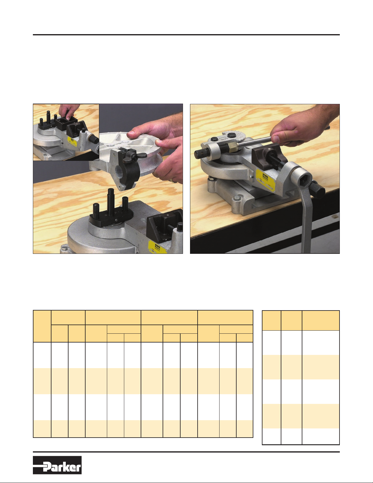
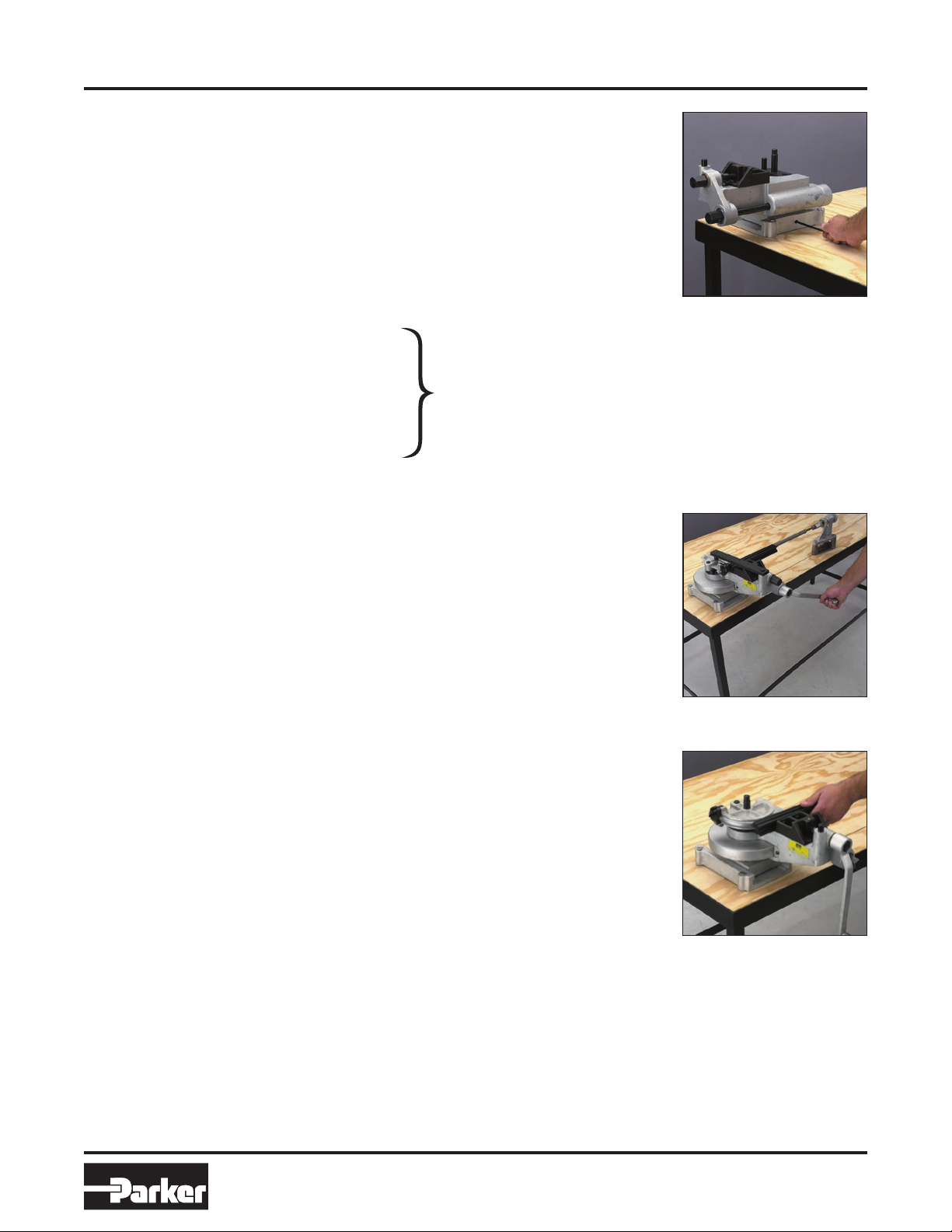
Step 5: Select Slide Block Groove
Select the proper groove of the slide block for the outside diameter
of the tube (sizes are marked on the end of the slide block) and
position the slide block accordingly, against the slide block vise face
with the end of the block adjacent to the tube clamp of the radius
block. Lubricate the slide block to facilitate sliding. Then, advance
the slide block by means of the telescopic adjustment screw, to rest
snugly against the tube, but not with so much pressure as to pre-
vent the block from sliding easily along the slide block vise face.
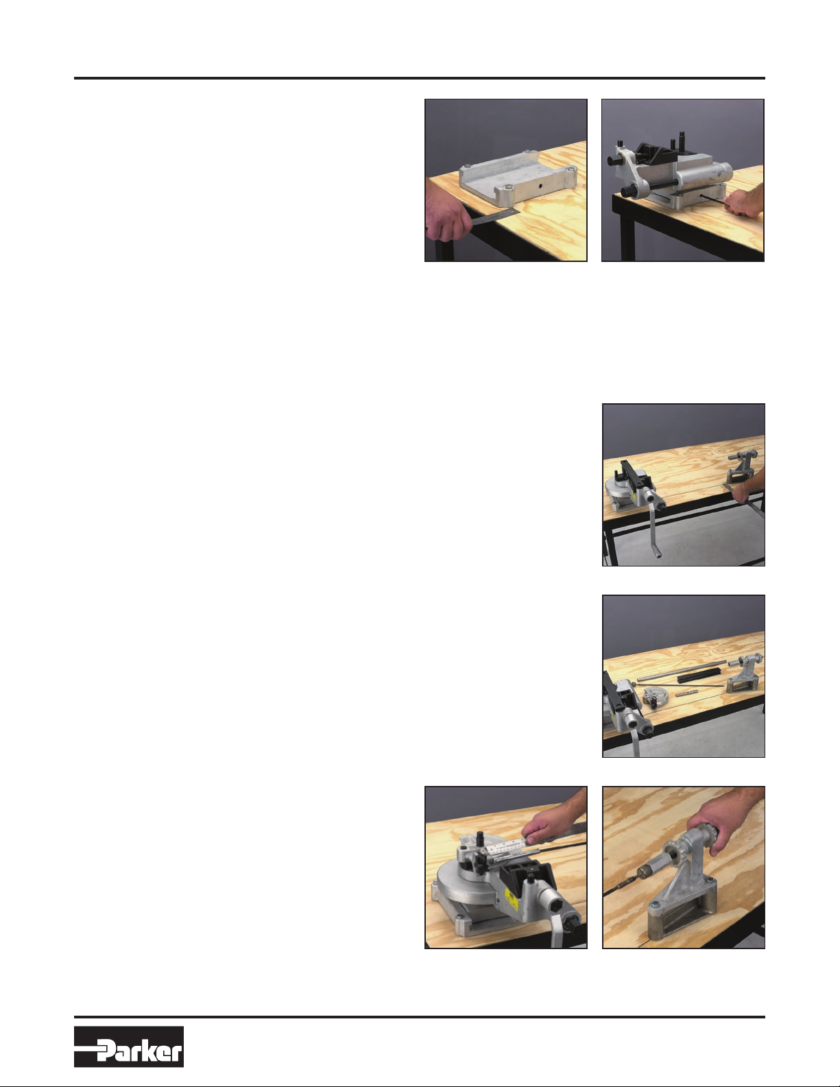
Step 6: Using the Tie Bar (if required)
When it becomes difficult to hold distortion of the tube within 5%
because of deflection of the bender, place the tie bar over the
center post and the dowel pin. Always use the tie bar with heavy
wall tubing — sizes 7/8" or above.
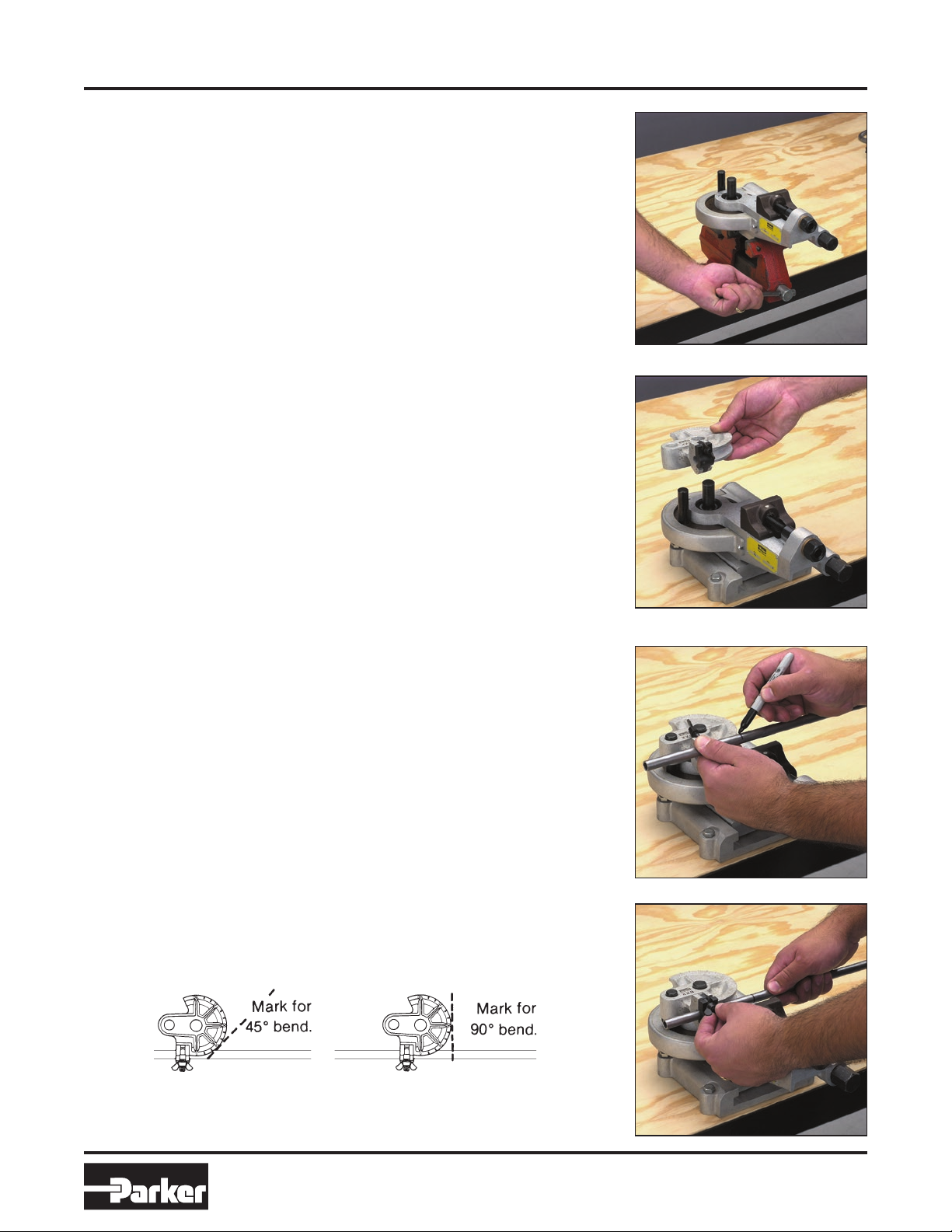
Step 7: Bend the Tube
Tube bending is accomplished with ease by means of the crank
handle operating the mechanism through 60:1 ratio worm gear.
As the bend is being made, the slide block travels with the tube
and bears lightly against the radius block to form a true round die
enclosing the tube, providing a smooth, full cross-section bend. The
angle of the bend is indicated by the marks on the radius block. At
the completion of bend the desired degree mark will be in line with
the left side of the bender.
Step 8: After Bending the Tube
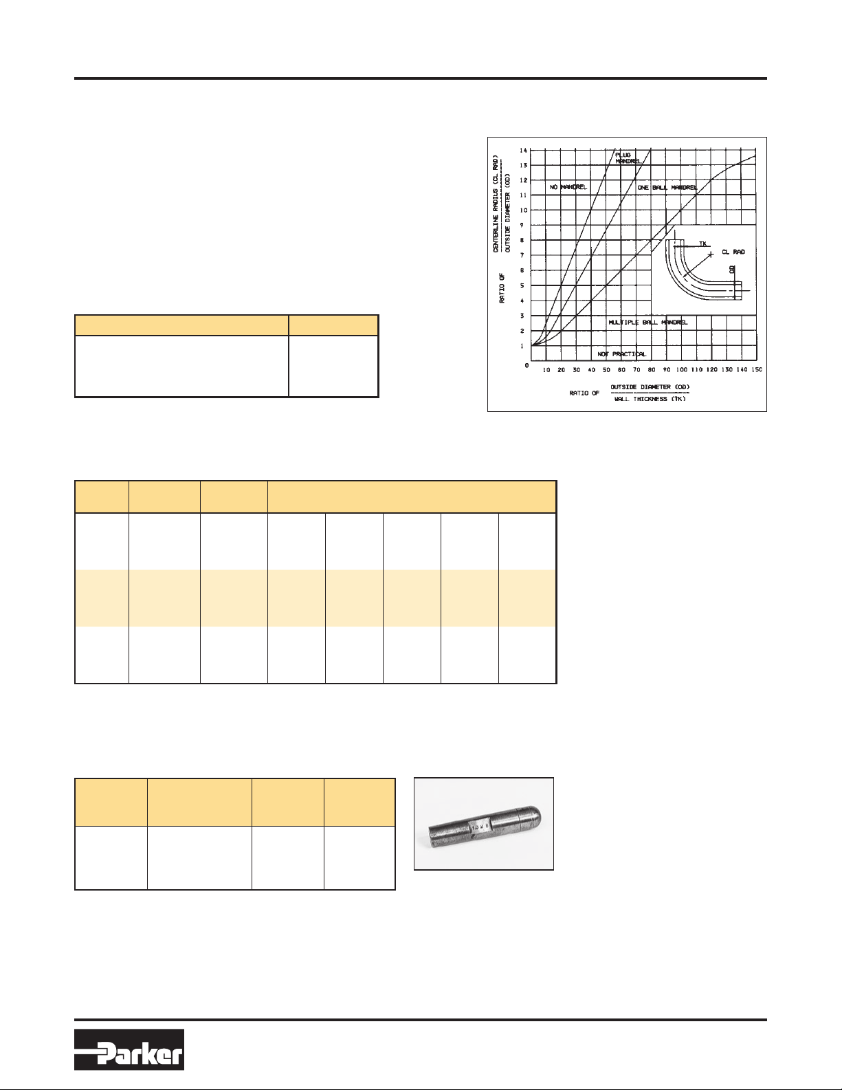
First, remove the tie bar, if in use. Next,
retract the slide block vise and remove the
slide block.
Step 9: Completed Bent Tube
Loosen the wing nut on the clamp, open, pull
the tube out from the radius block and lift up.
Your tubing is smoothly bent, without flatten-
ing or cracking.
To reset the tube bender, turn the worm
wheel shaft counterclockwise to disengage.
Turn the radius block back until the 0° mark
is at its original starting point. The bender is
then ready for inserting the next tube. Then
turn the worm wheel shaft in clockwise direc-
tion to re-engage the gear for the start of the
next bend.
Bends from 90° to 180° — The 400 Series Tube Benders bend tubing up to 180° with ease. The procedure for
bends over 90° is the same as for bends to 90°. See Step 4.

Bulletin 4391-B400S EXACTOL®400 Series Tube Benders
6Parker Hannifin Corporation
Tube Fittings Division
Columbus, OH
www.parker.com/tfd
Thin Wall Tube Bending with Mandrel Equipment
Instructions for Thin Wall Tube Bending with Mandrel Equipment
When bending thin wall tube it may be necessary to insert a
mandrel into the tube to prevent excessive distortion or flatten-
ing. To accomplish such bending, a Mandrel, Mandrel Rod, and
a Mandrel Rod Stop Assembly are required. The Rod Stop
Assembly holds the end of the Mandrel Rod in proper alignment
with the tube while the Mandrel, which is threaded onto the other
end of the Mandrel Rod, supports the tube on its I.D., thus
preventing tube kinking or flattening during bending.
Mandrel Graph Chart
Mandrel
Mandrel Rod Specifications & Data
Mandrel
Rod Dia.
(in.)
Tube I.D.
(in.)
Part
No.
Mandrel
Type
1/4 0.283 to 0.362 520506 solid
5/16 0.363 to 0.484 520507 solid
13/32 0.485 to 1.489 520508 solid
To order mandrel rods, specify mandrel rod size
and mandrel type.
Mandrels (Plug Type)
Size
Tube O.D.
(in.)
Part
No.
Wall Thickness
(in.)
6 3/8 924417 — 0.035 0.042 — —
8 1/2 924417 — 0.035 0.042 0.049 —
10 5/8 924417 0.035 0.042 0.049 0.058 0.065
12 3/4 924417 0.035 0.042 0.049 0.058 0.065
14 7/8 924417 0.035 0.042 0.049 0.058 0.065
16 1 924417 0.035 0.042 0.049 0.058 0.065
18 1 1/8 924417 — 0.049 0.058 0.065 —
20 1 1/4 924417 — 0.049 0.058 0.065 —
24 1 1/2 924417 0.049 0.058 0.065 0.083 —
To order mandrels, specify tube O.D. and wall thickness.
Example: 924417-12X058
Mandrel Equipment
Description Part No.
Mandrel Rod Stop Assembly 550571
Stop Assembly Adapter Riser (424 only) 631154
Mandrel Rod Stop 820029

Bulletin 4391-B400S EXACTOL®400 Series Tube Benders
7Parker Hannifin Corporation
Tube Fittings Division
Columbus, OH
www.parker.com/tfd
Thin Wall Tube Bending with Mandrel Equipment
Step 3: Select Radius Block Mandrel and Rod
Select the proper radius block according to the chart as described in Step
2 on page 4. Select the Mandrel according to the outside diameter and
wall thickness of the tubing. The selected Mandrel is screwed onto one
end of the mandrel rod. The other end of the mandrel rod is screwed onto
the adapter and then into the rod stop assembly.
Step 1: Mount Bender in Adapter Assembly
For mandrel bending, it is necessary to in-
stall the bender in a bench mounting adapter
assembly. Locate the adapter assembly
front mounting holes about 3” from the front
edge of the bench, with T slot front to back
and scale on the right. Secure the bender in
the adapter assembly by tightening the flat
head screws in the bottom of the adapter
slide. Then place the bender in the mounting
assembly with the axis of its drive handle
shaft parallel with the T slot. This places the
handle end of the bender towards the opera-
tor with the adapter scale to the right. (The
adapter slide and scale will be used later to
align the bender with the mandrel).
Step 2: Install Mandrel Rod Stop Assembly
Draw a centerline for the mandrel rod stop assembly and height adapter
to the right of the reference mark (A) on the adapter assembly. Position
the rod-stop assembly and height adapter on this line with the single
mounting hole nearest the bender.
Step 4: Adjust Mandrel
For average bending, the mandrel should be
adjusted so that the scribed line on its cir-
cumference is 5/8” behind the 0 mark on the
radius block. Make this adjustment by turning
locknuts on the mandrel rod stop assembly.
The mandrel may be moved forward slightly
to produce a more nearly perfect round
cross-section of the bent tube, or it may be
moved slightly backward to ease the bending
effort. However, extremes in either direction
may cause wrinkling, breaking, or flattening
of the tube.

Bulletin 4391-B400S EXACTOL®400 Series Tube Benders
8Parker Hannifin Corporation
Tube Fittings Division
Columbus, OH
www.parker.com/tfd
Thin Wall Tube Bending with Mandrel Equipment
Step 6: Mark Tube
Step 7: Clamp Tube
Step 8: Select Slide Block Groove
Step 9: Using the Tie Bar (if required)
These four steps are the same
as Steps 3, 4, 5 and 6 shown
on pages 4-5.
Step 10: Bend the Tube
Mandrel tube bending is easily accomplished by means of the crank
handle operating the mechanism through the 60:1 ratio worm gear. As the
bend is being made, the slide block travels with the tube and bears lightly
against the radius block to form a true round die enclosing the tube, pro-
viding a smooth, full cross-section bend.
Step 11: After Bending Tube
At the completion of the bend, remove the tie bar, retract the slide block
vise and unscrew the wing nut on the radius block clamp. Then, to
remove the tube, slide it out to the left, back along the axis of the mandrel
assemble. Loosen the mandrel assembly if necessary to facilitate tube
removal.
Step 5: Adjust Adapter Slide
Loosen the Allen head screw in slide adapter base and move the bender
to adjust for the radius block in use. Position the slide indicator pointer to
the radius of the radius block being used, in order to properly center the
radius block with respect to the tube and mandrel rod. Then tighten the
adapter slide screw with the Allen wrench.

Bulletin 4391-B400S EXACTOL®400 Series Tube Benders
9Parker Hannifin Corporation
Tube Fittings Division
Columbus, OH
www.parker.com/tfd
Model 412 Parts Schematic
Model 412 Tube Bender/Maintenance and Parts List
Bender Maintenance
All parts should be kept clean and free from dirt and
grit. Slide block and radius blocks should be handled
carefully to avoid damaging the smooth grooved surfac-
es. Presence of nicks, burrs, pieces of dirt or chips may
mar the surface of the tube and thereby weaken it.
All threaded parts should be cleaned and slightly
greased occasionally to keep them in good working
condition. This equipment will operate efficiently for a
long period of time and will bend to exact tolerances
repeatedly if these precautions are heeded.
Model 412 Parts List (Part # 560569)
Item
# Description
Part
No.
No.
Req’d
1 Body 13001 1
2Worm 550602 1
3 Shaft 550603 1
4 Collar 550604 1
5 Pin, 3/16 x 3/4
Driv-lok, C
48 x 238 Drive Pin 1
6Snap Ring, Truarc
#5100-75
56 x 207 Snap Ring 1
7 Key, 1/8 sq. x 1" long 13008 2
8Bearing, “Nice”
1207-22
550606 1
9Bearing, “Nice” 400-
26
550608 1
10 Worm Gear and Drive
Post Assembly
550587 1
11 Bearing, N.D. 99504 550592 2
12 Center Post 13016 1
13 Bearing Stop 550615 2
14 Screw, 10-32 x 1/2 rd.
Head
13023 2
15 Worm Nut 550610 1
16 Bearing, “Nice”
603-1/4
550607 1
17 Pin 550611 1
18 Clamp Nut 550598 1
19 Pin, 3/16 x 1
Driv-lok, C
48 x 240 Rd Hd Screw 1
20 Bearing, “Oilite”
F-1025-6
550597 2
21 Screw Pilot 550596 1
22 Screw, Clamp 550599 1
23 Retaining Screw 550594 1
25 Slide Shoe 550593 1
27 Gear Guard 550590 1
28 Screw, 8/32 x 3/8
Rd. Hd.
13048 2
29 Nameplate 13049 1
30 Drive Screw, P.K.
type “U” #0 x 1/8
13050 4
31 Crank Handle
Subassembly
550612 1
32 Worm & Shaft
Subassembly (2-7)
550601 1
33 Worm Gear 550587 1
34 Dowel Pin 13021 1
35 Crank Handle 13502 1
36 Knob 13054 1
37 Shoulder Screw 13055 1

Bulletin 4391-B400S EXACTOL®400 Series Tube Benders
10 Parker Hannifin Corporation
Tube Fittings Division
Columbus, OH
www.parker.com/tfd
Model 424 Parts Schematic
Model 424 Tube Bender/Maintenance and Parts List
Bender Maintenance
All parts should be kept clean and free from dirt and
grit. Slide block and radius blocks should be handled
carefully to avoid damaging the smooth grooved surfac-
es. Presence of nicks, burrs, pieces of dirt or chips may
mar the surface of the tube and thereby weaken it.
All threaded parts should be cleaned and slightly
greased occasionally to keep them in good working
condition. This equipment will operate efficiently for a
long period of time and will bend to exact tolerances
repeatedly if these precautions are heeded.
Model 424 Parts List (Part # 621044)
Item
# Description
Part
No.
No.
Req’d
1 Body 621062 1
2 Dowel Pin, 5/8 x 1-1/2 13102 1
3Worm 621067 1
4 Shaft 621068 1
5 Collar 621069 1
6 Snap Ring Truarc #5100-75 56 x 212 1
7 Key, 3/16 sq. x 1-5/8 long 13110 1
8 Pin, Driv-lok Type A 1/4 dia. x 1 13111 1
9 Subassembly Work & Shaft 621066 1
10 Bearing, #D2620 13113 1
11 Bearing, #3038DS 13114 1
12 Bearing, #607 13115 1
13 Pin, Driv-lok Type E 1/4 dia. x 1-1/4 13117 1
14 Nut, Drive 621071 1
15 Plug, Bearing Retainer 621072 1
16 Screw, Pilot Adjusting 621073 1
17 Bearing, Flange, #FF-1102-6 “Oilite” 13123 2
18 Nut, Vise Jaw 621074 1
19 Pin, Vise Jaw Nut 621075 1
20 Screw, Vise Jaw Adjusting 621076 1
21 Vise Jaw 621077 1
22 Pin, Vise Jaw Adjusting Screw 621078 1
23 Center Post Subassembly 621079 1
24 Bearing, #55507 N.D. Double Row
Ball
13136 1
25 Gear, Worm 621080 1
26 Key, Worm Gear 1/4 sq. x 19/32 long
22x20
13160 2
27 Nut, Worm Gear Retaining 621081 1
28 Bearing, #499604 N.D. Single Row
Ball
13141 1
29 Lockwasher, #W-04 13142 1
30 Locknut, #N-04 13143 1
31 Guard, gear 621082 1
32 Screw, 1/4-28 x 5/8 long Round Hd.
Mach. 4 x 126
13367 1
33 Pin, Drive 621083 2
34 Tie, Bar 621084 1
35 Adapter & Pin Subassembly, Slide
Block
621085 1
36 Screw, 5/10-18 x 3/4 Soc. Hd. Cap 13152 1
37 Crank-handle Subassembly 621063 1
38 Nameplate 550609 1
39 Screw, #0 x1/8 Type “U” P.K. 13050 4
41 Center Post 13157 1
42 Drive Plate 13159 1
43 Key, 1/4 sq. x 19/32 13160 1
44 Washer 621070 1
45 Washer 621070 1
46 Dowel Pin 5/8 13163 1
47 Vise Jaw Adapter 13165 1
48 Dowel Pin 1/4 13166 1
67 Crank Handle 13168 1
68 Knob 13054 1
69 Screw 13055 1

Bulletin 4391-B400S EXACTOL®400 Series Tube Benders
11 Parker Hannifin Corporation
Tube Fittings Division
Columbus, OH
www.parker.com/tfd
Bender Kits
Model 412 Bender Kit
Part No. Description
560569 412 Bender Body
550585 Slide Block for Sizes 4-6-8-10-12
550579 Size 4 Radius Block
550581 Size 6 Radius Block
550582 Size 8 Radius Block
550583 Size 10 Radius Block
550584 Size 12 Radius Block
— Carrying case designed
specifically for the 412 Kit.
Model 424 Bender Kit
Part No. Description
621044 424 Bender Body
550585 Slide Block for Sizes 4-6-8-10-12
621045 Slide Block for Sizes 14-16-18-20
870150 Slide Block for Size 24
550579 Size 4 Radius Block
550581 Size 6 Radius Block
550582 Size 8 Radius Block
550583 Size 10 Radius Block
550584 Size 12 Radius Block
621047 Size 16 Radius Block
621049 Size 20 Radius Block
870149 Size 24 Radius Block
— No carrying case available.
This manual suits for next models
2
Table of contents
Other Parker Construction Equipment manuals
Popular Construction Equipment manuals by other brands

LAMETAL
LAMETAL Stark HT2600R Operating and maintenance manual

Lightway
Lightway HP CRYSTAL Series Installation instruction

Fayat Group
Fayat Group BOMAG BW 219 DH-5 Service manual

Safeaid
Safeaid TS7000 Operator's manual

Dynapac
Dynapac CA282D instruction manual

Baileigh Industrial
Baileigh Industrial MB-4X2 Operator's manual