1Parker Hannifin Corporation
Tube Fittings Division
Columbus, OH
Bulletin 4391-B26 Hydraulic Tube Bender
FluidConnectors
Introduction
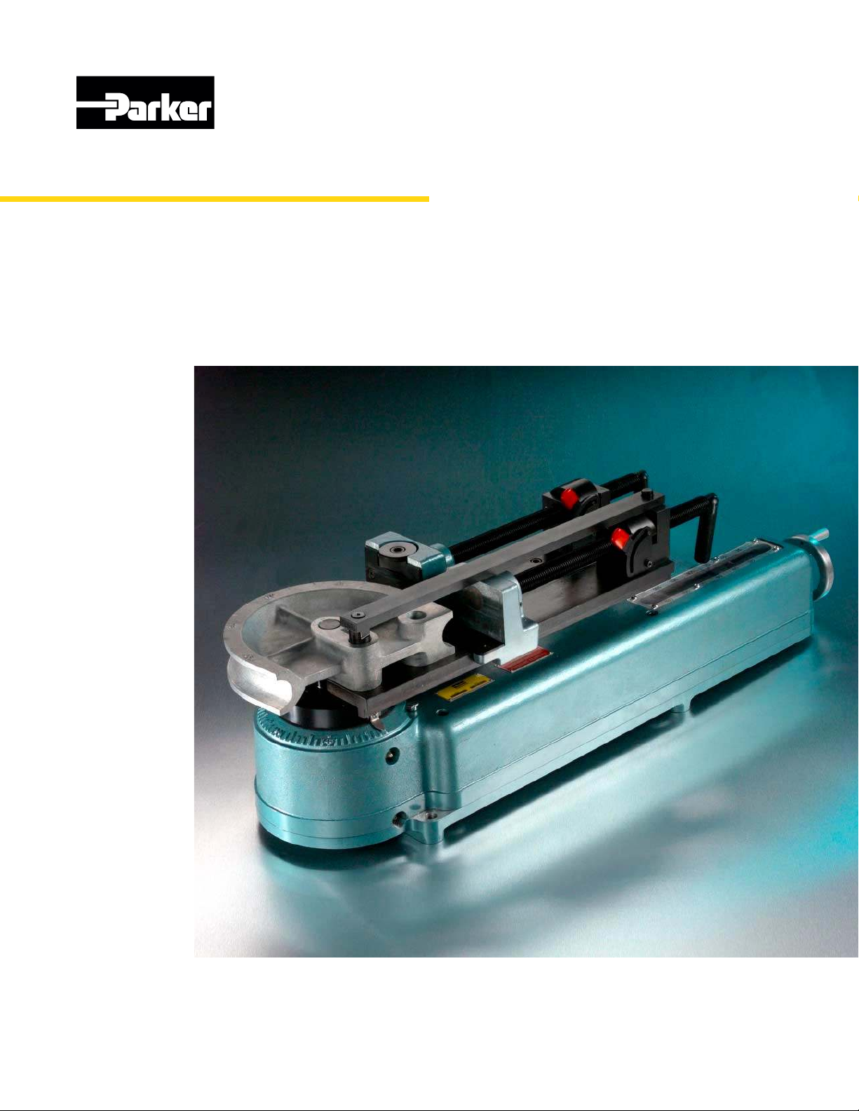
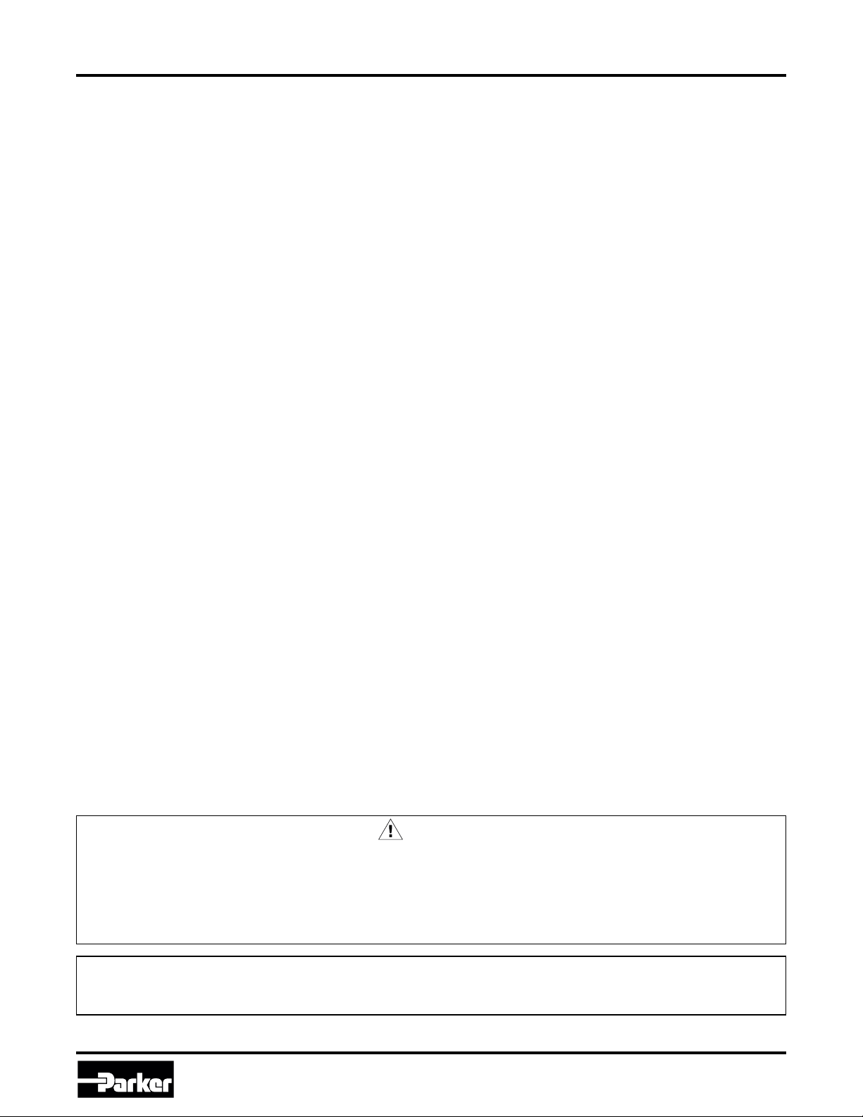
Parker Hydraulic Tube Bender
Model HB632
For 3/8" - 2" (10-50mm) tubing and 3/8 to
1 1/2 IPS
The Parker Model HB632 Tube Bender is a hydrauli-
cally operated bender for bending annealed steel and
stainless steel tubing from 3/8" O.D. through 2" O.D.
It is operated by means of a separate power source
producing 10,000 psi hydraulic pressure. It can be
operated without bolting to a table or bench if no man-
drels are required, making it an excellent unit to move
about and use at the point where the tubing installation
is being made. It can also be attached to a table and
used with mandrels. Part No.: 631050
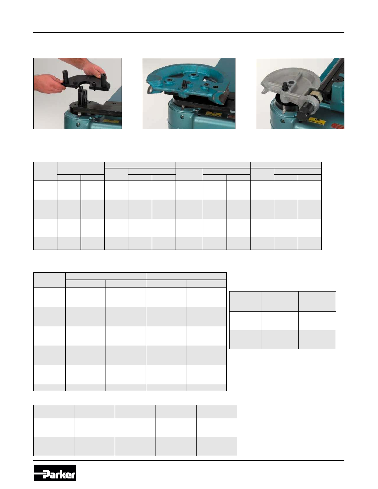
Bender Construction
The bender consists of a cast aluminum housing, with a
hydraulically actuated drive mechanism which enables an
operator to make bends up to 180° in one continuous smooth
operation on tubing up to 2" in diameter.
Capacity
Table 1 below assigns a Model Code for each model of
Parker tube benders. Table 2 gives the capacity for all
Parker benders. The Model HB632 is represented by
model code C so you can easily check for its capabilities.
Table 1 –Tube Bender Model Codes
Table 2 –Tube Benders Maximum Capacity Guide
* See page 3 for pipe bending capabilities
Specifications:
1) Min. tube size 3/8"
2) Max. tube size 2"
3) Min. bend radius 1 1/8"
4) Max. bend radius 12" (special order)
5) Max. tube bend 180°
6) Weight —170 lbs. (77.1 kg) without accessories
7) Minimum tube wall thickness (% of O.D.) 4% with mandrel, 7% without mandrel
8) The HB632 is capable of bending 1/2" O.D. and under fully annealed steel and
stainless steel tubing with no limit on tube wall thickness
9) The HB632 is capable of bending SOFT aluminum and copper tubing with no
limit on wall thickness.
10) For HARD copper, ALLOY STEEL, and HIGH STRENGTH aluminum, use the
tabulations shown for stainless steel.
Model
Code
Model
No.
Tubing O.D.
Capacity Bender Type
Rated Torque
(in./lbs.)
A 412 1/4" –3/4" Worm & Gear 2,700
B 424 1/4" –1-1/4" Worm & Gear 11,000
C HB632 1/4" –2" Hydraulic 52,000
D CP432 3/8" –2" Hydraulic N/A
Tube Bender Model Codes
0.035 0.049 0.058 0.065 0.072 0.083 0.095 0.109 0.120 0.134 0.156 0.188
S ABCD ABCD ABCD ABCD BCD BCD BCD BCD BCD BCD BCD BCD
SS BCD BCD BCD BCD BCD BCD BCD BCD BCD BCD BCD BCD
S BCD BCD BCD BCD BCD BCD BCD BCD BCD BCD BCD BCD
SS BCD BCD BCD BCD BCD BCD BCD BCD BCD BCD CD CD
S BCD BCD BCD BCD BCD BCD CD CD CD CD CD CD
SS BCD BCD BCD BCD BCD CD CD CD CD CD C C
S BCD BCD BCD BCD BCD CD CD CD CD CD CD CD
SS BCD BCD CD CD CD CD CD CD CD CD C C
S CDCDCDCDCDCDCDCDCDCDCDCD
SS CD CD CD CD CD CD CD CD CD CD ——
2"
Material
3/4"
1"
1-1/4"
1-1/2"
Tube Benders Maximum Capacity Guide*
Tube
O.D.
Tube Wall Thickness (inches)
Tube Bender Model Codes