Parker 6901 User manual

The Keypad 9-1
890CS Common Bus Supply - Frames B & D; 890CD Common Bus Drive and 890SD Standalone Drive - Frames B, C & D
Chapter 9 The Keypad
In this chapter, learn about the control keys and keypad indications. The main menu maps are
shown here, but for details of sub-menus refer to Chapter 10.
♦Introduction
♦6511 - Common Bus Supply
♦6901 - Common Bus Supply
♦6511 - Common Bus/Standalone Drive
♦6901 - Common Bus/Standalone Drive
♦Remote Mounting the Keypad

9-2 The Keypad
890CS Common Bus Supply - Frames B & D; 890CD Common Bus Drive and 890SD Standalone Drive - Frames B, C & D
Introduction
The 890 units are factory fitted with the 6511 Keypad. It
can be plugged into the front of the unit. To remove it,
simply pull it away from the drive. To refit it, push it
back into place.
You can also use a remote mounted 6901 Keypad.
Both the 6511 and 6901 Keypad can be mounted up to 3
metres away from the 890 using the optional panel
mounting kit with connecting lead: refer to "Remote
Mounting the Keypad", page 9-56.
The keypads display the following information:
890CS +DIAG menu (5 important diagnostics)
890CS +DIAGNOSTICS menu (5 important diagnostics)
890CD & 890SD +OPER, DIAG, SET & SYS menus
(SET menu is equivalent to the QUICK SETUP menu of the 6901)
890CD & 890SD +OPERATOR, DIAGNOSTICS, QUICK SETUP, SETUP &
SYSTEM menus (SETUP menu lists all parameters available in the
DSE 890 Configuration Tool)
6901 6511

The Keypad 9-3
890CS Common Bus Supply - Frames B & D; 890CD Common Bus Drive and 890SD Standalone Drive - Frames B, C & D
6511 Keypad
890CS Common Bus Supply
The 6511 Keypad (Man-Machine Interface, MMI) provides for local control (power-up/power-down), and
also monitoring of the five diagnostics provided on the display.
To display the Software Version:
Press and hold to display software version.
To display the Line Voltage Rating:
Press and hold to display software version. Press
or to view.
To Stop in
Local Mode:
Press
To Start in
Local Mode:
Press
Initial Powe
r
-Up Conditions
The unit will always power-up in Remote mode.
The Keypad will display the DC Link Power on the 890CS Common Bus Supply.
Programming Keys
Local
Key
Control
Local
Key
Control

9-4 The Keypad
890CS Common Bus Supply - Frames B & D; 890CD Common Bus Drive and 890SD Standalone Drive - Frames B, C & D
Control Key Definitions
Key Operation Description
Escape
Navigation –
Hold to display the Welcome screen
Trip Message
– Clear Trip or Error message from display
Menu Bypasses the time-out from the Welcome screen to display the Diagnostics
menu.
Increment Move up through the Diagnostics menu
Decrement Move down through the Diagnostics menu
Run
Local Mode
– Run the unit (power-up the DC link)
Stop
Local Mode
– Stops the unit (power-down the DC link)
Navigation –
Press and hold to toggle between Local and Remote Mode (refer
to page 9-8)
Trip Reset
– Resets trip condition allowing unit to resume operation
Example: To view the INPUT CURRENT diagnostic
1. The display will default to show the OUTPUT POWER (%) diagnostic .
2. Press the key repeatedly to scroll to the INPUT CURRENT (A) diagnostic .
Alternatively, press the key just once to cycle round the list.

The Keypad 9-5
890CS Common Bus Supply - Frames B & D; 890CD Common Bus Drive and 890SD Standalone Drive - Frames B, C & D
Display Indications
Rrotating = DC link charged
Indicates numbers or values,
trip information, error codes etc.
See "Status Indications" below.
Indicates the drive is in Local control.
Drive is in remote control when not visible.
Displays the units for the value:
for voltage in Volts,
for frequency in Hertz
for current in Amps
for percentage
V
Hz
A
%
when displaying an Alarm code
a negative parameter value
9-6 The Keypad
890CS Common Bus Supply - Frames B & D; 890CD Common Bus Drive and 890SD Standalone Drive - Frames B, C & D
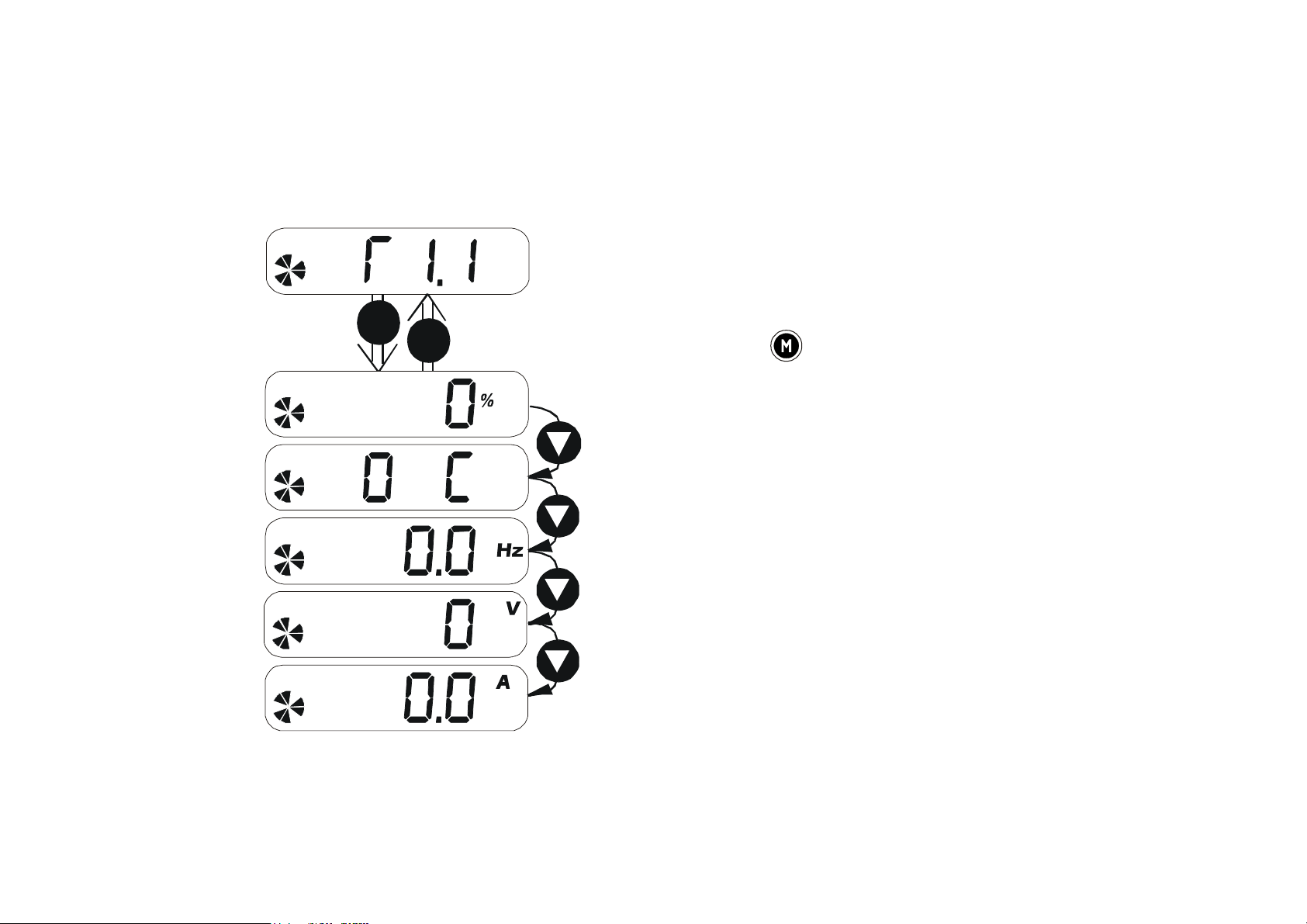
The Menu System
The unit will initialise in Remote Mode from factory conditions.
The Keypad will display the Output Power (%). This is the first of five diagnostics.
Welcome Screen Displays the software version of the unit
From the Welcome Screen, the display times-out (alternatively
you can press the key) to show the first of 5 diagnostics:
Output Power As a percentage of nominal full power for
the selected input voltage
Heatsink Temp The heatsink temperature in Centrigrade
Supply Frequency The real time frequency of the input supply
in Hz
DC Link Volts Vac (rms) x √2 = dc link Volts (when motor
stopped)
M
time-out
E
Input Current The real time input current in Amps
The Keypad 9-7
890CS Common Bus Supply - Frames B & D; 890CD Common Bus Drive and 890SD Standalone Drive - Frames B, C & D
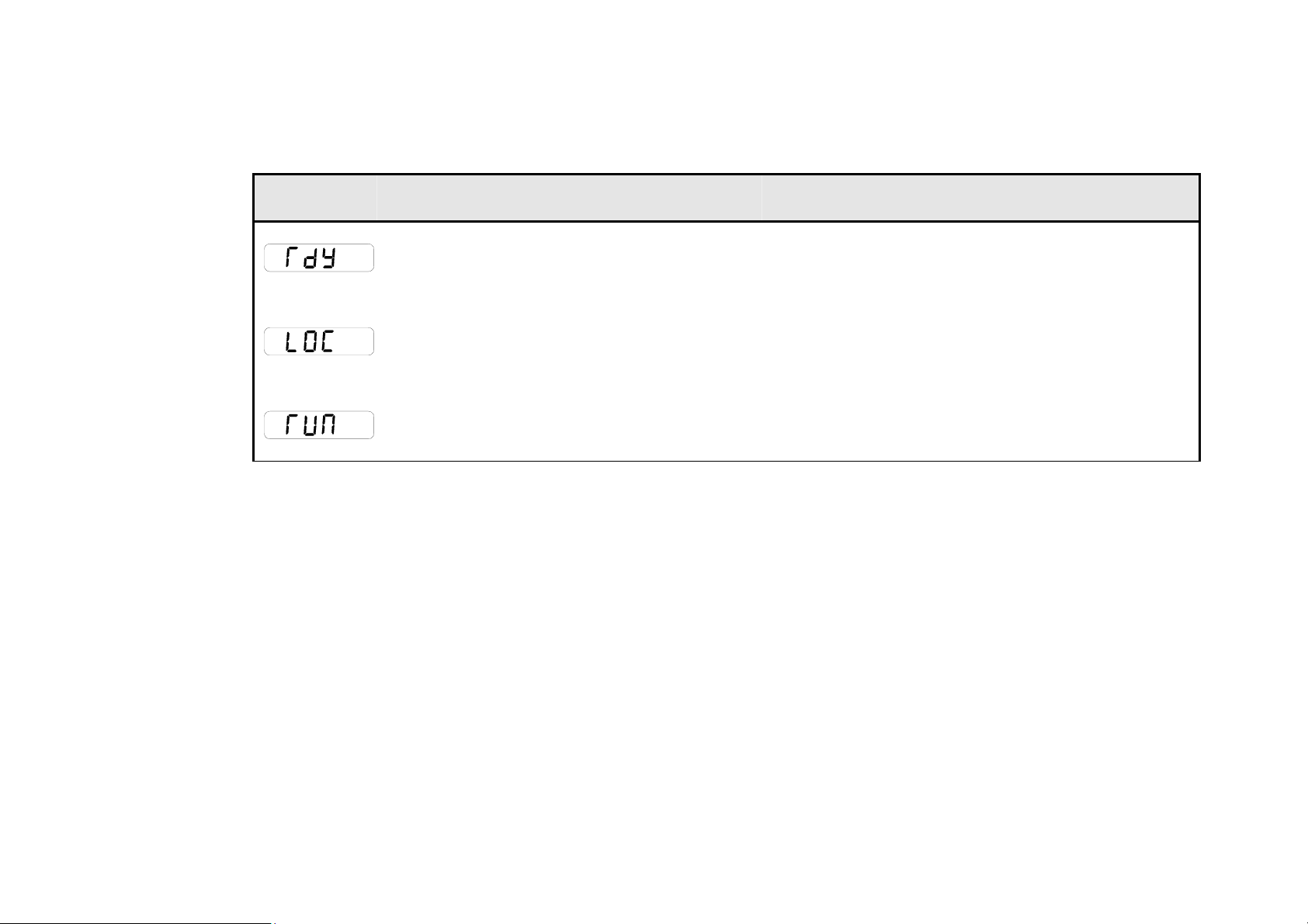
Drive Status Indications
The keypad can display the following status information:
Display Status Indication and Meaning Possible Cause
READY/HEALTHY No alarms present.
Remote mode selected
LOCAL Local Mode selected, healthy,
no alarms present
Added or removed from the display letter-
by-letter to indicate entering or leaving
Local Mode
RUN Not possible to change between
Local/Remote mode
The drive is running in Local mode or the
Remote run signal is active
Alert Message Displays
A message will be displayed on the Keypad when either:
♦A requested operation is not allowed
♦The drive has tripped
Most messages are displayed for only a short period, or for as long as an illegal operation is tried, however,
trip messages must be acknowledged by pressing the Ekey.
Experience will show how to avoid most messages. Refer to Chapter 11: “Trips and Fault Finding” for trip
messages and reasons.

9-8 The Keypad
890CS Common Bus Supply - Frames B & D; 890CD Common Bus Drive and 890SD Standalone Drive - Frames B, C & D
Selecting Local or Remote Mode
The unit can operate in one of two ways:
Remote Mode: Remote control using digital inputs
Local Mode: Local control using the Keypad
Local control keys are inactive when Remote mode is selected.
You can change between local and remote mode from any point on the MMI.
Note You can only change between Local and Remote Mode when the unit is “stopped” (when the DC link is
powered-down).
Remote to Local Mode:
Local to Remote Mode:
The ENABLE input (DIGIN2) must be inactive to effect this change.
REMOTE
LOCAL
Hold the Stop key down until
the display spells
Release the key to display
the previous menu
for example,Local Setpoint
REMOTE
LOCAL
Release the key to display
the previous menu
Hold the Stop key down until
and are removed from the display

The Keypad 9-9
890CS Common Bus Supply - Frames B & D; 890CD Common Bus Drive and 890SD Standalone Drive - Frames B, C & D
6901 Keypad
890CS Common Bus Supply
The 6901 Keypad (Man-Machine Interface, MMI)
provides for local control (power-up/power-down),
and also monitoring of the five diagnostics
provided on the display.
To display the Software Version & Voltage
Rating:
Press and hold to display software
version. Time-out or press .
To Stop in
Local Mode:
Press
To Start in
Local Mode:
Press
Initial Powe
r
-Up Conditions
The unit will always power-up in Remote mode.
The Keypad will display the DC Link Power on the 890CS Common Bus Supply.
E
M
PROG
L
R
Programming
Keys
Local
Control
Keys
JOG
1
DC 4Q 15A
DCDIVREIITGALD
OK SEQ REF
1
15kW 400V 1.x
ACDIVREOTORM

9-10 The Keypad
890CS Common Bus Supply - Frames B & D; 890CD Common Bus Drive and 890SD Standalone Drive - Frames B, C & D
Control Key Definitions
Key Operation Description
Escape
Navigation –
Hold to display the Welcome screen
Trip Message
– Clear Trip or Error message from display
Menu Bypasses the time-out from the Welcome screen to display the Diagnostics
menu
Increment Move up through the Diagnostics menu
Decrement Move down through the Diagnostics menu
Run
Local Mode
– Run the unit (power-up the DC link)
Stop
Local Mode
– Stops the unit (power-down the DC link)
Trip Reset
– Resets trip condition allowing unit to resume operation
R
L
Local/Remote Toggles between Remote and Local Mode
PROG
Prog
KEY INACTIVE
Forward/
Reverse
KEY INACTIVE
JOG
Jog
KEY INACTIVE
This manual suits for next models
1
Table of contents
Other Parker Keypad manuals


