6
The 6911 Keypad
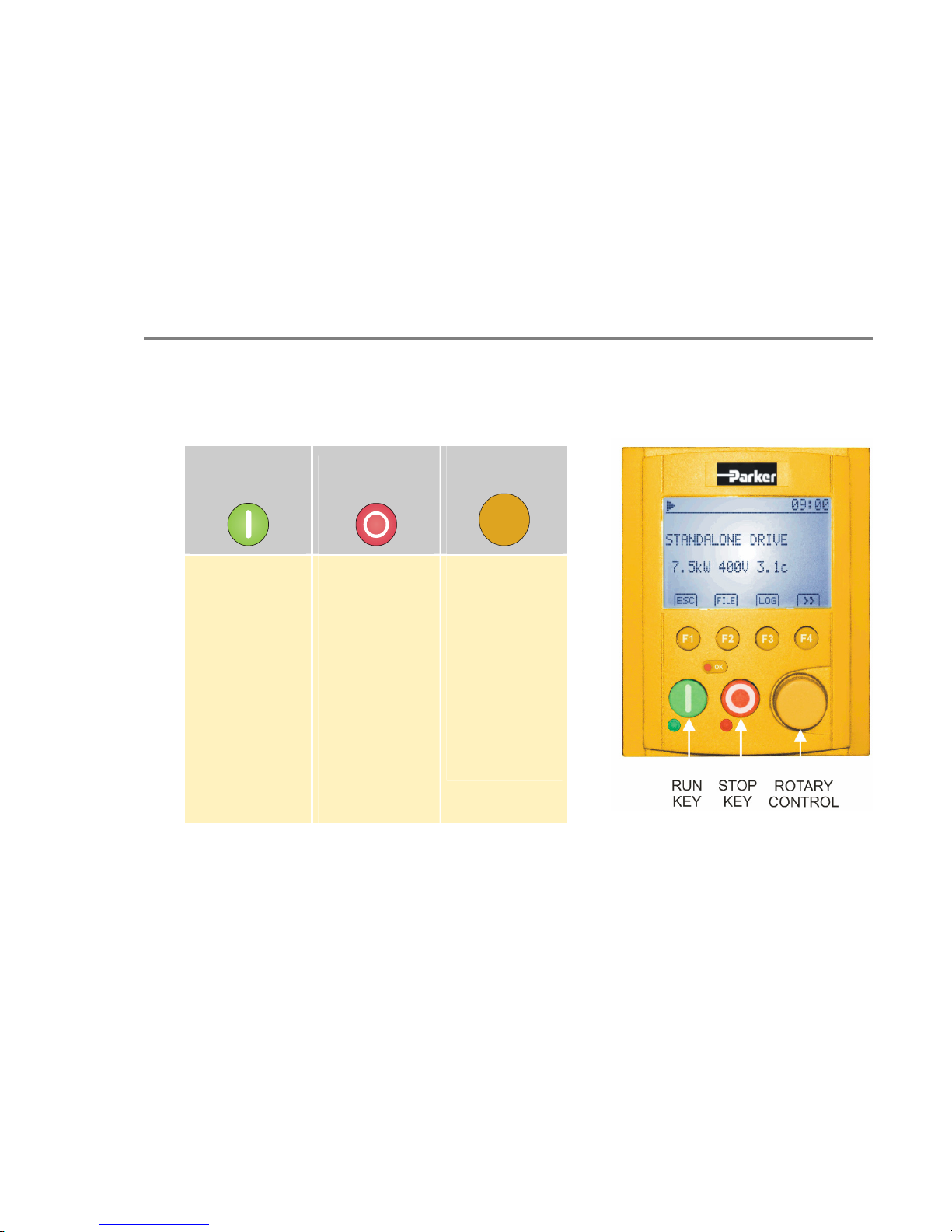
Connecting The Keypad
Insert the Keypad into the front of the drive or mount it up to 3 metres away using the optional panel mounting kit with the
RS232 connecting lead. Refer to "Remote Mounting the Keypad", page 6-28.
On some drives, two Keypads (or one and a PC running suitable programming software) can be used simultaneously. In this
case each Keypad runs independently.
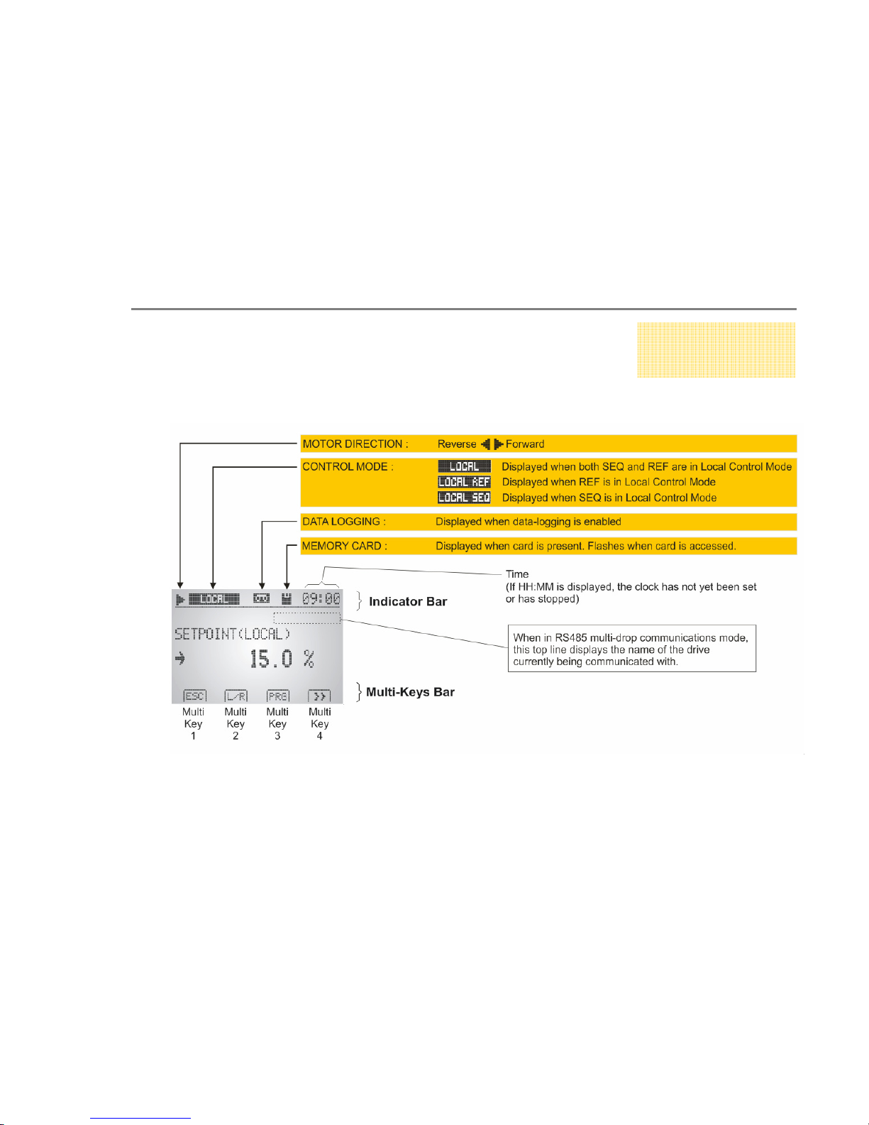
The drive can operate in one of two modes:
Remote Control Mode: Allowing access for application programming using digital and analog inputs and outputs
Local Control Mode: Providing local control and monitoring of the drive using the Keypad, or PC running suitable
programming software
Local control keys are inactive when Remote control mode is selected and vice versa, with one exception - the L/R selection
on Multi-Key 2, Set 2 toggles the Local or Remote control mode and so is always operative.
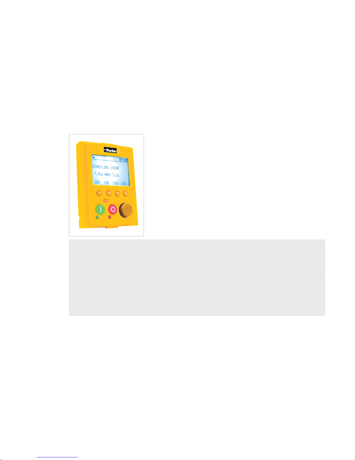
Initial Power-Up
On power-up, a default logo-screen is displayed for several seconds showing the
"Parker SSD" logo. If the display does not light, or a "comms code" is presented then
there is a connection error.
Future MMI software versions will allow the "Parker SSD" logo-screen to be replaced
with an image of your choice. This image can also be set as the timeout-screen and
will appear after a preset time of keypad inactivity.
After the logo-screen, the display shows the product description; power rating,
voltage and software version of the drive. A typical example is shown opposite.