Parker Compumotor 6200 User manual

Artisan Technology Group is your source for quality
new and certied-used/pre-owned equipment
• FAST SHIPPING AND
DELIVERY
• TENS OF THOUSANDS OF
IN-STOCK ITEMS
• EQUIPMENT DEMOS
• HUNDREDS OF
MANUFACTURERS
SUPPORTED
• LEASING/MONTHLY
RENTALS
• ITAR CERTIFIED
SECURE ASSET SOLUTIONS
SERVICE CENTER REPAIRS
Experienced engineers and technicians on staff
at our full-service, in-house repair center
WE BUY USED EQUIPMENT
Sell your excess, underutilized, and idle used equipment
We also offer credit for buy-backs and trade-ins
www.artisantg.com/WeBuyEquipment
REMOTE INSPECTION
Remotely inspect equipment before purchasing with
our interactive website at www.instraview.com
LOOKING FOR MORE INFORMATION?
Visit us on the web at www.artisantg.com for more
information on price quotations, drivers, technical
specications, manuals, and documentation
Contact us: (888) 88-SOURCE | sales@artisantg.com | www.artisantg.com
SM
View
Instra

Compumotor
Compumotor Division
Parker Hannifin Corporation
p/n 88-016454-01A September 1997
6200 Indexer
Installation Guide
SHLD
GND
2HOM
2CCW
2CW
GND
1HOM
1CCW
1CW
LIM 1/2
AUX
2-AXIS INDEXER
STATUS
O.K.
RESET
NO POWER
:
:
:
GREEN
RED
OFF
Compumotor
Rx
Tx
GND
SHLD
+5V
OUT-P
TRG-A
TRG-B
GND
OUT-A
OUT-B
GND
SHLD
P-CUT
RP240
6200
P
R
O
G
R
A
M
M
A
B
L
E
I
N
P
U
T
S
P
R
O
G
R
A
M
M
A
B
L
E
O
U
T
P
U
T
S
J
O
Y
S
T
I
C
K
+5V
GND
Rx
Tx
SHLD
AC INPUT
D
R
I
V
E
2
D
R
I
V
E
1
ENCODER 2
+5V
A+
A-
B+
B-
Z+
Z-
GND
SHLD
ENCODER 1
+5V
A+
A-
B+
B-
Z+
Z-
GND
SHLD
Artisan Technology Group - Quality Instrumentation ... Guaranteed | (888) 88-SOURCE | www.artisantg.com

6000 Series products and the information in this user guide are the proprietary property of Parker Hannifin Corporation or its licensers, and
may not be copied, disclosed, or used for any purpose not expressly authorized by the owner thereof.
Since Parker Hannifin constantly strives to improve all of its products, we reserve the right to change this user guide and software and
hardware mentioned therein at any time without notice.
In no event will the provider of the equipment be liable for any incidental, consequential, or special damages of any kind or nature
whatsoever, including but not limited to lost profits arising from or in any way connected with the use of the equipment or this user guide.
© 1992-7, Parker Hannifin Corporation
All Rights Reserved
User Information
WARNING
6000 Series products are used to control electrical and mechanical
components of motion control systems. You should test your motion
system for safety under all potential conditions. Failure to do so can result
in damage to equipment and/or serious injury to personnel.
! !
North America and Asia:
Compumotor Division of Parker Hannifin
5500 Business Park Drive
Rohnert Park, CA 94928
Telephone: (800) 358-9070 or (707) 584-7558
Fax: (707) 584-3793
FaxBack: (800) 936-6939 or (707) 586-8586
BBS: (707) 584-4059
e-mail: [email protected]
Internet: http://www.compumotor.com
Europe
(non-German speaking)
:
Parker Digiplan
21 Balena Close
Poole, Dorset
England BH17 7DX
Telephone: +44 (0)1202 69 9000
Fax: +44 (0)1202 69 5750
Germany, Austria, Switzerland:
HAUSER Elektronik GmbH
Postfach: 77607-1720
Robert-Bosch-Str. 22
D-77656 Offenburg
Telephone: +49 (0)781 509-0
Fax: +49 (0)781 509-176
Technical Assistance
Contact your local automation technology center (ATC) or distributor, or ...
Motion Architect is a registered trademark of Parker Hannifin Corporation.
Motion Builder, CompuCAM and DDE6000 are trademarks of Parker Hannifin Corporation.
Microsoft and MS-DOS are registered trademarks, and Windows, DDE and NetDDE are trademarks of Microsoft Corporation.
Motion Toolbox is a trademark of Snider Consultants, Inc.
LabVIEW is a registered trademark of National Instruments Corporation.
E-mail: 6000user@cmotor.com
Product Feedback Welcome
Automation
Artisan Technology Group - Quality Instrumentation ... Guaranteed | (888) 88-SOURCE | www.artisantg.com

6200
Documentation Enhancements
Topic Description
New Documentation Set The
6200 User Guide
(p/n 88-013168-01), which contained hardware and software
documentation, is replaced by this document (
6200 Installation Guide
, p/n 88-016454-01) and
the
6000 Series Programmer’s Guide
(p/n 88-014540-01).
Miscellaneous
Clarifications • All inputs and outputs are optically isolated from the internal microprocessor (not from the
other inputs and outputs).
•CAUTION: You must select either the on-board +5V terminal or an external 5-24VDC power
supply to power the OUT-P pull-up resistor. Connecting OUT-P to the +5V terminal and to an
external supply will damage the 6200.
LVD and EMC Installation
Guidelines The 6200 is in compliance with the Low Voltage Directive (72/23/EEC) and the CE Marking
Directive (93/68/EEC) of the European Community.
When installed according to the procedures in the main body of this installation guide, the 6200
may not necessarily comply with the Low Voltage Directive (LVD). To install the 6200 so that it is
LVD compliant, refer to supplemental installation instructions provided in Appendix A. If you do
not follow these instructions, the protection of the 6200 may be impaired.
The 6200 is sold as a complex component to professional assemblers. As a component, it is not
required to be compliant with Electromagnetic Compatibility Directive 89/336/EEC. However,
Appendix B provides guidelines on how to install the 6200 in a manner most likely to minimize
the 6200’s emissions and to maximize the 6200’s immunity to externally generated
electromagnetic interference.
Artisan Technology Group - Quality Instrumentation ... Guaranteed | (888) 88-SOURCE | www.artisantg.com

Artisan Technology Group - Quality Instrumentation ... Guaranteed | (888) 88-SOURCE | www.artisantg.com

Online Manuals This manual (in Acrobat PDF format) is available from our web site: http://www.compumotor.com
ABOUT THIS GUIDE
Chapter 1. Installation
What You Should Have (ship kit)...........................................................2
Before You Begin.....................................................................................2
Recommended Installation Process.............................................2
Electrical Noise Guidelines...........................................................2
General Specifications............................................................................3
Pre-installation Adjustments...................................................................4
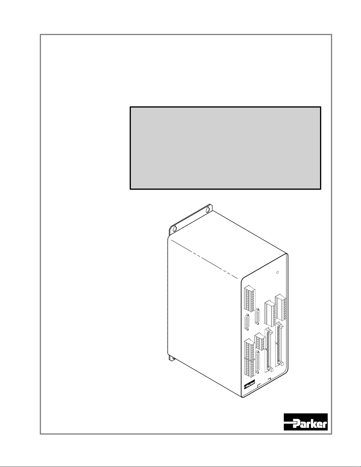
Mounting the 6200....................................................................................5
Electrical Connections............................................................................6
Grounding System..........................................................................6
Serial Communication (RS-232C)...............................................7
Pulse Cut-off (P-CUT) Input — Emergency Stop Switch...........7
Motor Drivers.................................................................................8
End-of-Travel and Home Limit Inputs.........................................10
Encoder.........................................................................................11
Joystick & Analog Inputs .............................................................12
Trigger Inputs................................................................................13
General-Purpose Programmable Inputs & Outputs...................14
RP240 Remote Operator Panel...................................................18
Input Power...................................................................................18
Lengthening I/O Cables................................................................19
Testing the Installation...........................................................................20
What’s Next?.........................................................................................22
Program Your Motion Control Functions....................................22
Chapter 2. Troubleshooting
Troubleshooting Basics.........................................................................24
Reducing Electrical Noise...........................................................24
Diagnostic (“STATUS”) LED......................................................24
Test Options..................................................................................24
Technical Support.........................................................................24
Common Problems & Solutions...........................................................25
Troubleshooting Serial Communication Problems.............................26
Product Return Procedure....................................................................27
Appendix A (LVD Installation Instructions)......................29
Appendix B (EMC Installation Guidelines)........................31
Index..................................................................................................35
Quick Reference...............................................(see back cover)
Purpose of This Guide
This document is designed to help you install and troubleshoot your 6200 hardware system.
Programming related issues are covered in the 6000 Series Programmer’s Guide and the 6000
Series Software Reference.
What You Should Know
To install and troubleshoot the 6200, you should have a fundamental understanding of:
• Electronics concepts, such as voltage, current, switches.
• Mechanical motion control concepts, such as inertia, torque, velocity, distance, force.
• Serial communication and terminal emulator experience: RS-232C
Related Publications •6000 Series Software Reference, Parker Hannifin Corporation, Compumotor Division;
part number 88-012966-01
•6000 Series Programmer’s Guide, Parker Hannifin Corporation, Compumotor Division;
part number 88-014540-01
• Current Parker Compumotor Motion Control Catalog
• Schram, Peter (editor). The National Electric Code Handbook (Third Edition). Quincy,
MA: National Fire Protection Association
LVD & EMC Compliance
The 6200 is in compliance with the Low Voltage Directive (72/23/EEC) and the CE Marking
Directive (93/68/EEC) of the European Community.
When installed according to the procedures in the main body of this installation guide, the 6200
may not necessarily comply with the Low Voltage Directive (LVD). To install the 6200 so
that it is LVD compliant, refer to supplemental installation instructions provided in Appendix
A. If you do not follow these instructions, the protection of the 6200 may be impaired.
The 6200 is sold as a complex component to professional assemblers. As a component, it is
not required to be compliant with Electromagnetic Compatibility Directive 89/336/EEC.
However, Appendix B provides guidelines on how to install the 6200 in a manner most likely
to minimize the 6200’s emissions and to maximize the 6200’s immunity to externally
generated electromagnetic interference.
Artisan Technology Group - Quality Instrumentation ... Guaranteed | (888) 88-SOURCE | www.artisantg.com

Artisan Technology Group - Quality Instrumentation ... Guaranteed | (888) 88-SOURCE | www.artisantg.com

1
CHAPTER ONE
Installation
IN THIS CHAPTER
• Product ship kit list
• Things to consider before you install the 6200
• General specifications table
• Optional pre-installation alterations (requires removal of chassis)
- DIP switch settings for device address and autobaud feature
- Jumper setting for programmable inputs to source or sink current
• Mounting the 6200
• Connecting all electrical components (includes specifications)
• Testing the installation
• Preparing for what to do next
To install the 6200 so that it is LVD compliant, refer to the supplemental instructions in
Appendix B. Appendix C provides guidelines on how to install the 6200 in a manner
most likely to minimize the 6200’s emissions and to maximize the 6200’s immunity to
externally generated electromagnetic interference.
Artisan Technology Group - Quality Instrumentation ... Guaranteed | (888) 88-SOURCE | www.artisantg.com

2
6200 Installation Guide
What You Should Have
(ship kit)
Part Name Part Number
If an item is missing,
call the factory (see
phone numbers on
inside front cover).
6200 standard product (with ship kit).......................................................6200
Ship kit: (2) 10-foot, 15 D to 25 D drive cables..................................71-010432-01
120VAC 8-foot power cord....................................................44-000054-01
240VAC connector.................................................................44-011905-01
This user guide (
6200 Installation Guide
)............................88-016454-01
6000 Series Software Reference
..........................................88-012966-01
6000 Series Programmer’s Guide
.......................................88-014540-01
Motion Architect diskettes: Disk 1......................................95-013070-01
Disk 2......................................95-013070-02
Driver & Samples Disk.........95-016324-01
Before You Begin
WARNINGS
The 6200 is used to control your system’s electrical and mechanical components. Therefore,
you should test your system for safety under all potential conditions. Failure to do so can
result in damage to equipment and/or serious injury to personnel.
Always remove power to the 6200 before:
• Connecting any electrical device (e.g., drive, encoder, inputs, outputs, etc.)
• Adjusting the DIP switches or other internal components
Recommended Installation Process
This chapter is
organized
sequentially to best
approximate a typical
installation process.
1. Review the general specifications.
2. Perform configuration/adjustments (if necessary).
3. Mount the 6200.
4. Connect all electrical system components.
5. Test the installation.
6. Mount the motor and couple the load.
7. Program your motion control functions. Programming instructions are provided in the
6000 Series Programmer’s Guide and in the 6000 Series Software Reference. We
recommend using the programming tools provided in Motion Architect for Windows (found
in your ship kit). You can also benefit from the optional iconic programming interface
called Motion Builder (sold separately) and from other software tools listed on page 22.
Electrical Noise Guidelines
• Do not route high-voltage wires and low-level signals in the same conduit.
• Ensure that all components are properly grounded.
• Ensure that all wiring is properly shielded.
• Page 19 provides noise suppression guidelines for lengthening I/O cables.
• Appendix B (page 31) provides guidelines on how to install the 6200 in a manner most
likely to minimize the 6200’s emissions and to maximize the 6200’s immunity to
externally generated electromagnetic interference.
Artisan Technology Group - Quality Instrumentation ... Guaranteed | (888) 88-SOURCE | www.artisantg.com

Chapter 1. Installation
3
General Specifications
Parameter Specification
Power
AC input....................................................................110-240VAC (±10%) single-phase, 50/60Hz, 0.6A @ 120VAC.
Status LED................................................................GREEN if proper AC input power supply is connected.
RED if power reset is required.
OFF if no power.
Environmental
Operating Temperature ..........................................32 to 122°F (0 to 50°C).
Storage Temperature...............................................-22 to 185°F (-30 to 85°C).
Humidity...................................................................0 to 95% non-condensing.
Performance
Position Range & Accuracy.....................................Position range: ±2,147,483,648 steps;
Accuracy: ±0 steps from preset total.
Velocity Range, Accuracy, & Repeatability............Range: 1-2,000,000 steps/sec;
Accuracy: ±0.02% of maximum rate;
Repeatability: ±0.02% of set rate.
Acceleration Range.................................................. 1-24,999,975 steps/sec2.
Motion Algorithm Update Rate................................2 ms.
Serial Communication
Connection Options..................................................RS-232C, 3-wire (Rx, Tx & GND on the AUX connector).
Maximum units in daisy-chain................................99 (use DIP switch or ADDR command to set individual addresses for each unit).
Communication Parameters...................................9600 baud (range is 9600-1200—see
AutoBaud
, page 4), 8 data bits, 1 stop bit, no parity;
full duplex.
Inputs
All inputs are optically isolated from the microprocessor (not from the other inputs).
Home; CW/CCW Limits; Triggers; Pulse Cut; ....TTL compatible* with internal 6.8 KΩpull-up resistor to +5V; Voltage range = 0-24V.
Joystick inputs (pins 15-19): Axes Select,
Velocity Select, Trigger, Release, and Auxiliary.
Drive Fault and In Position (DRIVE connector)......TTL compatible* with internal 1.0 KΩpull-up resistor to +5V; Voltage range = 0-5V.
Encoder.....................................................................Differential comparator accepts two-phase quadrature incremental encoders with differential
(recommended) or single-ended outputs.
Maximum voltage = 5VDC. Switching levels are TTL-compatible*.
Maximum frequency = 1.6 MHz. Minimum time between transitions = 625 ns.
24 General-Purpose Programmable .....................TTL compatible* with internal 6.8 KΩpull-ups to +5V (sourcing current). To sink current on
(PROGRAMMABLE INPUTS connector)..................all programmable inputs, change internal jumper JU2 to position 1/2. Voltage range = 0-24V.
Analog input channels (JOYSTICK connector).......Voltage range = 0-2.5VDC; 8-bit A/D converter. Input voltage must not exceed 5V.
Outputs
All outputs are optically isolated from the microprocessor (not from the other outputs).
26 Programmable (includes OUT-A & OUT-B)........Open collector output with 10.0 KΩpull-ups. Can be pulled up by connecting OUT-P to power
source (+5V terminal or an external 5-24V supply); OUT-P can handle 0-24V with max.
current of 50mA. Outputs will sink up to 30mA or source up to 5mA at 5-24VDC. 24
general-purpose outputs on Programmable Outputs connector, OUT-A & OUT-A on AUX
connector.
+5V Output................................................................Internally supplied +5VDC. +5V terminals are available on multiple connectors. Load limit
(total load for all I/O connections) is 1.5A.
Step, Direction, Shutdown (DRIVE connector).......Differential line driver output. Signal high > 3.5VDC @ +30mA, signal low < 1.0VDC @
-30mA. +output for each differential driver is active high; -output for each driver is active
low. Step pulse width is 0.3 µs to 20 µs (depending on the PULSE command—0.3 µs default).
* TTL-compatible switching voltage levels: Low ≤0.4V, High ≥2.4V.
Artisan Technology Group - Quality Instrumentation ... Guaranteed | (888) 88-SOURCE | www.artisantg.com

4
6200 Installation Guide
Pre-installation Adjustments — Optional
Factory Settings May Be Sufficient (if so, skip this section)
•DIP Switches (Device Address Selection; Autobaud Feature): Device address is set to zero. NOTE: If you are connecting
multiple units in a daisy-chain or multi-drop, you can automatically establish the device address by using the ADDR command,
thereby eliminating the need to access the internal DIP switches. The factory default baud rate is 9600 (maximum setting).
•Jumper JU2 (Configuring the Programmable Inputs as Sourcing or Sinking): The factory configuration is that all of the general-
purpose programmable inputs (24 inputs on the PROGRAMMABLE INPUTS 50-pin connector) source current; that is, they are
pull-up to the internal +5V supply through internal jumper JU2.
CAUTIONS
• Remove power before removing the 6200’s enclosure (unplug the AC power cord).
• Remove the screw-terminal connectors from the front panel and make sure the clips on the 50-pin
connectors are pushed inward so that they do not catch on the front panel.
• While handling the 6200 printed circuit assembly (PCA), be sure to observe proper grounding
techniques to prevent electro-static discharge (ESD).
DIP Switch
Factory Default Setting Shown
Switches 1-3 ...... Address Selection
Switch 4 ............. AutoBaud Feature
N
O
1234
To implement the Auto Baud feature:
Switch #4 ON = Auto Baud Enabled
Switch #4 OFF = Auto Baud Disabled (default)
The default baud rate is 9600. As an alternative, you can use
this procedure to automatically match your terminal's speed
of 1200, 2400, 4800, or 9600 baud.
1. Set switch 4 to ON.
2. Connect the 6200 to the terminal.
3. Power up the terminal.
4. Cycle power to the 6200 and immediately press the
space bar several times.
5. The 6200 should send a message with the baud rate
on the first line of the response. If no baud rate message
is displayed, verify steps 1-3 and repeat step 4.
6. Change switch 4 to OFF.
7. Cycle power to the 6200. This stores the baud rate
in non-volatile memory.
NOTE: If Auto Baud is enabled, the 6200 performs its auto
baud routine every time it is powered up or reset. The 6200
is only capable of matching 1200, 2400, 4800, and 9600
baud. Once the baud rate has been determined, the 6200
stores that baud rate in non-volatile memory; therefore,
Switch #4 should be set to the OFF position after the baud
rate has been determined.
AUTO BAUD
OFF OFF OFF Ø (default)
ON OFF OFF 1
OFF ON OFF 2
ON ON OFF 3
OFF OFF ON 4
ON OFF ON 5
OFF ON ON 6
ON ON ON 7
* Device address is checked upon power up or reset.
Switch #1 Switch #2 Switch #3 Device Address
ADDRESS
Jumper JU2
Factory Default Setting Shown
Internal Programmable
Input Circuit
ISO GND
74HCTxx47 KΩ
Input
Connection
Ground
Connection
ISO
GND
6.8 KΩ
This is the default
setting for Jumper JU2
(inputs source current).
Moving JU2 to the 1/2
position causes inputs
to sink current.
+5VDC
1
2
3
1
2
3
SINKING OR SOURCING PROGRAMMABLE INPUTS
Artisan Technology Group - Quality Instrumentation ... Guaranteed | (888) 88-SOURCE | www.artisantg.com

Chapter 1. Installation
5
Mounting the 6200
Before you mount the 6200
Check the list below to make sure you have performed all the necessary configuration tasks that require
accessing internal components (DIP switches and jumper JU2).
•Select device address (DIP switches). If you are not connecting multiple 6200 units in an RS-232C daisy chain, use the
factory setting. If you need to change this setting, refer to page 4 for instructions.
•Select sinking or sourcing configuration for the 24 programmable inputs (jumper JU2). If your application requires the 6200’s
24 programmable inputs (on the PROGRAMMABLE INPUTS connector) to source current, use the factory setting. If your
application requires the programmable inputs to sink current, refer to page 4 for instructions.
4.20 (106.68)
2.70 (68.58) 0.75 (19.05)
10.80
(274.32)
10.00
(254.00)
Provision for #10
Mounting Screws
(4 Plcs.)
0.80 (20.32)
11.60
(294.64)
0.60 (15.25)
7.76 (197.10)
inches (millimeters)
8.53 (216.66)
Environmental
Considerations Temperature. Operate the 6200 in ambient temperatures
between 32°F (0°C) and 122°F (50°C). Provide a minimum of
2 inches (50.8 mm) of unrestricted air-flow space around the
6200 chassis (see illustration). Fan cooling may be necessary
if adequate air flow is not provided.
Humidity. Keep below 95%, non-condensing.
Airborne Contaminants, Liquids. Particulate
contaminants, especially electrically conductive material, such
as metal shavings and grinding dust, can damage the 6200. Do
not allow liquids or fluids to come in contact with the 6200 or
its cables.
2.0
(50.8)
2.0
(50.8)
2.0
(50.8)
2.0
(50.8)
M
i
n
i
mum A
i
r
f
low
S
pace = 2
i
nches
Artisan Technology Group - Quality Instrumentation ... Guaranteed | (888) 88-SOURCE | www.artisantg.com

6
6200 Installation Guide
Electrical Connections
To install the 6200 so that it is LVD compliant, refer also to the
supplemental instructions in Appendix A (page 29).
Appendix B (page 31) provides guidelines on how to install the 6200 in a
manner most likely to minimize the 6200’s emissions and to maximize the
6200’s immunity to externally generated electromagnetic interference.
Grounding System
LIM 1/2
AUX RP240
J
O
Y
S
T
I
C
K
P
R
O
G
R
A
M
M
A
B
L
E
I
N
P
U
T
S
P
R
O
G
R
A
M
M
A
B
L
E
O
U
T
P
U
T
S
SHLD
GND
ENCODER 1
SHLD
GND
SHLD
GND
SHLD
GND
GND
SHLD
Shield Pin #8
GND Pin #14
Even numbered pins
AC Connector Ground Pin
GND
SHLD
SHLD Terminals
SHLD Terminal
GND Terminal
GND Terminal
GND Terminal
GND Terminals
Isolated
Ground EARTH
D
R
I
V
E
2
GND
GND Pins #13 & #14
D
R
I
V
E
1
ENCODER 2
GND
GND Terminal
SHLD Terminal
GND Terminal
GND Terminal
Opto-Isolation on Inputs and Outputs
The inputs and outputs are isolated from the internal micro-processor,
but are not isolated from the other inputs and outputs.
Artisan Technology Group - Quality Instrumentation ... Guaranteed | (888) 88-SOURCE | www.artisantg.com

Chapter 1. Installation
7
Serial Communication (RS-232C)
Rx
Tx
GND
SHLD
Rx
Tx
GND
SHLD
Rx
Tx
GND
SHLD
RS-232C Connections
Tx
Rx
GND
RS-232C Daisy-Chain Connections*
Unit 0 Unit 1 Unit 2
Tx
Rx
GND
Daisy Chain to a Computer or Terminal
Stand-Alone Daisy Chain
Be sure to set unique devices addresses for each unit.
To set the address, use the DIP switch (see page 4),
or use the ADDR command (see
6000 Series Software Reference
).
*
NOTE: Maximum RS-232C cable length is 50 feet (15.25 meters)
AUX
Rx
Tx
GND
SHLD
Rx
Tx
GND
SHLD
Rx
Tx
GND
SHLD
Unit 0 Unit 1 Unit 2
Rx
Tx
GND
SHLD
25-Pin COM Port:9-Pin COM Port:
Serial Port Connection
Pin 2 (Rx)
Pin 3 (Tx)
Pin 5 (GND)
Pin 2 (Tx)
Pin 3 (Rx)
Pin 7 (GND)
Rx
Tx
GND Rx
Tx
GND
Pulse Cut-off (P-CUT) Input — Emergency Stop Switch
TRG-A
TRG-B
GND
OUT-A
OUT-B
GND
SHLD
P-CUT
AUX Connector
TTL compatible (switching levels: low ≤0.4V, high ≥2.4V).
Voltage range = 0-24V.
Internal Schematic
ISO
GND
6.8 KΩ
47 KΩ74HCTxx
+5VDC
7
1
7
P-CUT connected to GND (normally-closed switch).
If this connection is opened, motion is killed and the
program in progress is terminated.
If the P-CUT input is not grounded when motion is
commanded, motion will not occur and the error
message “WARNING: PULSE CUT INPUT ACTIVE”
will be displayed in the terminal emulator.
Artisan Technology Group - Quality Instrumentation ... Guaranteed | (888) 88-SOURCE | www.artisantg.com

8
6200 Installation Guide
Motor Drivers
PIN OUTS & SPECIFICATIONS
(15-pin DRIVE Connector)
15 D
Pin # Cable (71-010432-10)
Color (25 D Pin #) Name In/Out Description
1 Red (pin #1) Step (+) OUT Differential output. Step (pulse) output to the drive. Step + signal is active high.
Signal levels: Low ≤1.0VDC @ -30mA, High ≥3.5VDC @ +30mA.
2 Green (pin #2) Direction (+) OUT Differential output. High signal on Direction + specifies motion in the positive
direction; Low signal on Direction + specifies motion in the negative direction.
Signal levels: Low ≤1.0VDC @ -30mA, High ≥3.5VDC @ +30mA.
3—
Reserved
— -----------------------
4 Gray (pin #10) In-Position IN Used for digital servo drives to indicate that the motor has reached the target
position. TTL switching levels (Low ≤0.4V, High ≥2.4V). Voltage range: 0-5V.
5 Yellow (pin #9) Drive Fault IN An active-high (current not flowing) signal that tells the 6200 a drive has faulted. TTL
switching levels (Low ≤0.4V, High ≥2.4V). You can use the DRFLVL command to
change the active level to low (current flowing) if desired. NOTE: Drive Fault input
will not be recognized until the input functions are enabled with INFEN1 command.
6—
Reserved
— -----------------------
7 — +5V OUT +5V output.
8 Bare Wire (pin #5) Shield — Connected to chassis (earth) ground within the 6200.
9 Black (pin #14) Step Return (-) IN Differential output. Step (pulse) output to the drive. Step - signal is active low.
10 White (pin #15) Direction Return (-) IN Differential output. Low signal on Direction - specifies motion in the positive
direction; High signal on Direction - specifies motion in the negative direction.
11 Blue (pin #16) Shutdown (+) OUT Differential output. This signal is used to turn off current in the motor windings. High
signal on Shutdown + indicates the motor winding current should be off.
Signal levels: Low ≤1.0VDC @ -30mA, High ≥3.5VDC @ +30mA.
12 Purple (pin #17) Shutdown Return(-) IN Differential output. This signal is used to turn off current in the motor windings. Low
signal on Shutdown - indicates the motor winding current should be off.
13 Orange (pin #21) Ground — Isolated logic ground
14 Brown (pin #22) Ground — Isolated logic ground
15 —
Reserved
— -----------------------
INTERNAL SCHEMATICS
Step, Direction & Shutdown Outputs
+5VDC
GND
15-Pin
DRIVE Connector
Step +
Direction +
Shutdown +
Step -
Direction -
Shutdown -
Shutdown Output Circuit Current Flow
(Active vs. Inactive)
Shutdown +
Shutdown -
Current
Flow
(Active)
Current
Flow
(Active)
Current
Flow
(Inactive)
Current
Flow
(Inactive)
Drive Fault and In-Position Inputs
+5VDC
GND
74HCTxx
1 KΩ
15-Pin
DRIVE Connector
Drive Fault or
In-Position
Ground
(pin 13 or 14)
15-Pin
DRIVE Connector
+5VDC
GND
+5VDC
GND
+5VDC
GND
CONNECTIONS
WARNING
Make sure the drive is off before
connecting it to the 6200.
15-pin D
Connector
Drive Motor
Plug-compatible with most
Compumotor and Digiplan drives
(exceptions are illustrated below).
Connect to DRIVE connector
25-pin D
Connector
Connect to drive
10-foot cables provided in ship kit (p/n 71-010432-10).
Maximum recommended cable length is 50 feet.
Pin outs and cable color code provided in table above.
71-010432-10
Artisan Technology Group - Quality Instrumentation ... Guaranteed | (888) 88-SOURCE | www.artisantg.com

Chapter 1. Installation
9
Direction Return (pin 10) Direction Return (pin 15)
Step + (pin 1) Step + (pin 1)
Direction + (pin 2) Direction + (pin 2)
Drive Fault (pin 5) Fault Output (pin 9)
Step Return (pin 9) Step Return (pin 14)
Shutdown Return (pin 12) Shutdown Return (pin 17)
Ground (pin 13 or 14) Fault Return (pin 21)
6200
(DRIVE Connector)
Connecting a ZETA, S, OEM650, OEM750 or PDS Drive
Shutdown + (pin 11) Shutdown + (pin 16)
Shield (pin 8)
ZETA, S, OEM or PDS Drive
(25-pin Connector)
Use the 71-010432-10 10-foot cable for plug compatibility with ZETA, S, OEM, and PDS.
Direction Return (pin 10) Direction Return (pin 15)
Step + (pin 1) Step + (pin 3)
Direction + (pin 2) Direction + (pin 4)
Drive Fault (pin 5) ISO Fault + (pin 22)
Step Return (pin 9) Step Return (pin 14)
Shutdown Return (pin 12) Shutdown Return (pin 13)
Ground (pin 13 or 14) Fault Return (pin 23)
6200
(DRIVE Connector)
OEM670SD Drive
Connecting an OEM670SD Drive
Shutdown + (pin 11) Shutdown + (pin 12)
Shield (pin 8)
Direction – (pin 10) Direction – (pin 19)
Step + (pin 1) Step + (pin 45)
Direction + (pin 2) Direction + (pin 20)
Drive Fault (pin 5) Servo Ready + (pin 15)
Step – (pin 9) Step – (pin 46)
Shutdown – (pin 12) Servo On + (pin 24)
Ground (pin 13) Servo Ready – (pin 16)
6200
Connecting a Dynaserv Drive
Shutdown + (pin 11) Servo On – (pin 23)
Shield (pin 8)
Dynaserv
(50-pin DN1 Connector)
Order the 71-012985-10 10-foot cable for easy plug compatibility with the Dynaserv.
B – (pin 5) B – (pin 30)
A + (pin 8) A – (pin 14)
B + (pin 6) B + (pin 29)
A – (pin 7) A + (pin 13)
Z – (pin 3) Z – (pin 44)
Z + (pin 4) Z + (pin 43)
DRIVE ConnectorENCODER Connector
In Position + (pin 4) In Position + (pin 27)
Ground (pin 14) In Position – (pin 28)
Direction – (pin 10) Direction – (pin 37)
Step + (pin 1) Step + (pin 15)
Direction + (pin 2) Direction + (pin 13)
Drive Fault (pin 5) Servo Ready + (pin 31)
Step – (pin 9) Step – (pin 39)
Shutdown – (pin 12) Servo On + (pin 1)
Ground (pin 13) Servo Ready – (pin 26)
6200
Connecting a Linearserv Drive
Ground (pin 14) Servo On – (pin 5)
Linearserv
(50-pin CN1 Connector)
B – (pin 5) B – (pin 43)
A + (pin 8) A – (pin 41)
B + (pin 6) B + (pin 19)
A – (pin 7) A + (pin 17)
Z – (pin 3) Z – (pin 45)
Z + (pin 4) Z + (pin 21)
DRIVE ConnectorENCODER Connector
In Position + (pin 4) In Position + (pin 7)
Shield (pin 8)
6200
(DRIVE Connector)
Step + (pin 1)
PKH130M Drive
Direction + (pin 2)
Drive Fault (pin 5)
Shutdown Return (pin 12)
Direction Return (pin 10)
Step Return (pin 9)
Ground (pin 13 or 14)
Shield (pin 8)
Clock (pin 6)
Direction (pin 5)
Fault (pin 2)
Reset (pin 7)
0V (pin 8)
Connecting a PKH130M Drive
Artisan Technology Group - Quality Instrumentation ... Guaranteed | (888) 88-SOURCE | www.artisantg.com

10
6200 Installation Guide
End-of-Travel and Home Limit Inputs
NOTES
• Motion will not occur on an axis until you do one of the following:
- Install end-of-travel (CW & CCW) limit switches.
- Disable the limits with the LHØ command (recommended only if load is not coupled).
- Change the active level of the limits with the LHLVL command.
• Refer to the
Basic Operation Setup
chapter in the
6000 Series Programmer’s Guide
for
in-depth discussions about using end-of-travel limits and homing.
CONNECTIONS & INTERNAL SCHEMATICS
Internal Schematic
CW & CCW connected to GND (normally-closed switches).
Mount each switch such that the load forces it to open before it
reaches the physical travel limit (leave enough room for the load to
stop). When the load opens the switch, the axis stops at the decel
value set with the LHAD command. The motor will not be able to
move in that same direction until you execute a move in the opposite
direction and clear the limit by closing the switch (or you can disable
the limits with the LHØ command, but this is recommended only if the
motor is not coupled to the load). The active level (default is active
low) can be changed with the LHLVL command.
HOM connected to GND (normally-open switch).
The home limit input is used during a homing move, which is initiated
with the HOM command. After initiating the homing move, the
controller waits for the home switch to close, indicating that the load
has reached the “home” reference position. The active level (default
is active low) can be changed with the HOMLVL command. You can
also use an encoder’s Z channel pulse, in conjunction with the home
switch, to determine the home position (this feature is enabled with
the HOMZ1 command).
Chassis
Ground
ISO GND
All limit inputs share the
same circuit design.
LIM 1/2 Connector SHLD
GND
2HOM
2CCW
2CW
GND
1HOM
1CCW
1CW
6.8 KΩ
47 KΩ74HCTxx
+5VDC
9
1
PIN OUTS & SPECIFICATIONS
(LIM 1/2 Connector)
Pin Name In/Out Description Specification for all limit inputs
1
2
3
4
5
6
7
8
9
SHLD
GND
2HOM
2CCW
2CW
GND
1HOM
1CCW
1CW
—
—
IN
IN
IN
—
IN
IN
IN
Chassis ground (earth).
Isolated ground.
Home limit input, axis 2.
Negative-direction end-of-travel limit input, axis 2.
Positive-direction end-of-travel limit input, axis 2.
Isolated ground.
Home limit input, axis 1.
Negative-direction end-of-travel limit input, axis 1.
Positive-direction end-of-travel limit input, axis 1.
• TTL compatible switching levels (Low ≤0.4V, High ≥2.4V).
Internal 6.8 KΩpull-up resistor to +5V. Voltage range = 0-24V.
• Active level for HOM is set with HOMLVL (default is active low,
requires n.o. switch).
• Active level for CW & CCW is set with LHLVL (default is active
low, requires n.c. switch).
Artisan Technology Group - Quality Instrumentation ... Guaranteed | (888) 88-SOURCE | www.artisantg.com

Chapter 1. Installation
11
Encoder
CONNECTIONS & INTERNAL SCHEMATICS
ENCODER Connector
+5VDC
Red Red
A Channel +
Brown White
A Channel –
Brown/White
(n/a)
B Channel +
Green Brown
B Channel –
Green/White
(n/a)
Z Channel +
Orange Blue
Z Channel –
Orange/White
(n/a)
Ground
Black Black
Shield
Shield Shield
Internal Schematic
Colors for Compumotor-supplied Encoders:
-E Series encoders
-RE encoder on OS motor (OSxxx-xxx-RE)
-RC encoder on OS motor (OSxxx-xxx-RC)
-EC encoder on RS motor (RSxxx-xxx-EC)
Encoders on OEM Series motors (except 57 size)
Incremental
Encoder
Max. Cable Length is 100 feet.
Use 22 AWG wire.
+5V
A+
A–
B+
B–
Z+
Z–
GND
SHLD
9
ISO
GND
22 KΩ
22 KΩ
+5VDC
Same Circuit
as A Channel
Chassis GND
+5VDC
1
Colors for -HJ encoder on OS motor (OSxxx-xxx-HJ),
and 57-size OEM Series encoders.
(These are single-ended encoders.)
+1.8VDC
PIN OUTS & SPECIFICATIONS
(ENCODER Connector)
Pin Name In/Out Description
9
8
7
6
5
4
3
2
1
+5V
A+
A–
B+
B–
Z+
Z–
GND
SHLD
OUT
IN
IN
IN
IN
IN
IN
-----
-----
+5VDC output to power the encoder.
A+ Channel quadrature signal input.
A– Channel quadrature signal input.
B+ Channel quadrature signal input.
B– Channel quadrature signal input.
Z+ Channel signal input.
Z– Channel signal input.
Isolated ground.
Shield
—Internally connected to chassis ground (earth).
Specification for all encoder inputs
Differential comparator accepts two-phase quadrature
incremental encoders with differential (recommended) or
single-ended outputs. Max. frequency is 1.6 MHz. Minimum
time between transitions is 625 ns. TTL-compatible voltage
levels: Low ≤0.4V, High ≥2.4V. Maximum input voltage is
5VDC.
Requirements for Non-Compumotor Encoders
• Use incremental encoders with two-phase quadrature output. An index or
Z channel
output is optional.
Differential outputs are recommended.
• It must be a 5V (< 200mA) encoder to use the 6200’s +5V output. Otherwise, it must be separately powered
with TTL-compatible (low ≤0.4V, high ≥2.4V) or open-collector outputs.
• If you are using a single-ended encoder, leave the A–, B– and Z– terminals on the 6200 unconnected.
Artisan Technology Group - Quality Instrumentation ... Guaranteed | (888) 88-SOURCE | www.artisantg.com

12
6200 Installation Guide
Joystick & Analog Inputs
CONNECTIONS
SHLD
+5VDC
Analog Channel 1
Analog Channel 2
Velocity Select
Axes
Select
Joystick
Release
Joystick Trigger
GND
Velocity Select
Axes Select
N.O. Momentary
Joystick Trigger
Joystick potentiometers are 5K
Ω
with
60
°
of usable travel adjusted to span
0
Ω
to 1K
Ω
.
N.C. Momentary
Joystick Release
1KΩResistors
*
5KΩ
X Axis
5KΩ
Y Axis
Joystick Auxiliary
Joystick Aux.
Joystick
The 1K
Ω
resistors for velocity select,
axes select, joystick trigger, & joystick
auxiliary are for noise suppression only.
*
J
O
Y
S
T
I
C
K
23
1
2
16
15
17
18
19
14
8
Feedrate Control
(Using a Potentiometer)
1KΩ
1KΩ
+5VDC
Analog Channel
GND
J
O
Y
S
T
I
C
K
23
14
*
8
* Pins 1, 2 and 3
SHLD
Joystick
INTERNAL SCHEMATICS
25-Pin
JOYSTICK Connector
GND
74HCTxx
6.8 KΩ
47 KΩ
Input
Terminal
(Pins 15-19)
Ground
Terminal
(Pin 14)
+5VDC
150 KΩ
49.9 KΩ0.1 µF
10.0 KΩ35 V
35 V
This input circuit applies to Axes Select, Velocity Select,
Joystick Release, Joystick Trigger, & Joystick Auxiliary.
Analog Channel
Input Terminal
(Pins 1-3)
Ground
Terminal
(Pin 14)
+5VDC +5VDC
GND
8 Channel
8-bit A/D
Converter
Analog Channel Input CircuitJoystick Input Circuit
TTL compatible:
Low ≤0.4V; High ≥2.4V
25-Pin
JOYSTICK Connector
PIN OUTS & SPECIFICATIONS
Pin In/Out Name Description
1 IN Analog Channel 1 Analog input for feedrate control or joystick control of axis. Voltage range is 0-2.5VDC, 8-bit A/D
converter. CAUTION: Input voltage must not exceed 5VDC.
2 IN Analog Channel 2 (same description as pin 1 above).
3 IN Analog Channel 3 (same description as pin 1 above).
8 — Shield Shield (chassis ground).
14 — Ground Digital ground.
15 IN Axes Select If using one joystick, you can use this input to alternately control axes 1 & 2. *
16 IN Velocity Select Input to select high or low velocity range (as defined with the JOYVH or JOYVL commands). *
17 IN Joystick Release When low (grounded), joystick mode can be enabled. When high (not grounded), program
execution will continue with the first command after the joystick enable (JOY) statement. *
18 IN Joystick Trigger Status of this active-low input can be displayed with the TINOF command, or read by a program
(using the INO command) to control program flow or to enter the 6200 into joystick mode (JOY1). *
19 IN Joystick Auxiliary Status of this active-low input can be displayed with the TINOF command, or read by a program
(using the INO command) to control program flow. *
23 OUT +5VDC (out) +5VDC power output.
* Input voltage range for pins 15-19 is 0-24VDC. TTL compatible (switching voltage levels: Low ≤0.4V, High ≥2.4V).
Artisan Technology Group - Quality Instrumentation ... Guaranteed | (888) 88-SOURCE | www.artisantg.com

Chapter 1. Installation
13
Trigger Inputs
TRG-A and TRG-B connected to GND (normally-open switches).
The active level (default is active low) can be changed with the INLVL
command.
These inputs are like the general-
purpose inputs on the 50-pin header.
The differences are (1) the triggers
are always internally pulled up to +5V
and are not affected by jumper JU2;
and (2) the triggers can be
programmed with the INFNCi-H
command to function as position
capture inputs and registration inputs.
TTL compatible (switching levels: low ≤0.4V, high ≥2.4V).
Voltage range = 0-24V.
TRG-A
TRG-B
GND
OUT-A
OUT-B
GND
SHLD
P-CUT
7
1
7Both trigger inputs share
a common circuit design.
AUX Connector
Internal Schematic
6.8 KΩ
47 KΩ74HCTxx
+5VDC
ISO
GND
Chassis
Ground
Connection to a Sinking Output Device
TRG-A
TRG-B
GND
OUT-A
OUT-B
GND
SHLD
P-CUT
7
1
7
Electronic Device
Out 5-24 VoltsOutput
Ground
The output should
be able to sink at
least 1mA of current.
6200
AUX
6.8 KΩ
47 KΩ74HCTxx
+5VDC
ISO GND
Connection to a Sourcing Output Device
TRG-A
TRG-B
GND
OUT-A
OUT-B
GND
SHLD
P-CUT
7
1
7
AUX
6.8 KΩ
47 KΩ74HCTxx
+5VDC
ISO GND
Electronic Device
Out 5-24 VoltsOutput
Ground
V1
R1
R
Typical value for R = 450Ω(assuming R1= 0)
Note: The value of R may vary depending on the value of R1and V1.
6200
The resistor provides a path for current to flow from the device when the output is active.
PROGRAMMING TIP
Connecting to a sinking output? Set the trigger input’s active level to low with the INLVL command
(Ø= active low,
default setting
). Connecting to a sourcing output? Set the trigger input’s active
level to high with the INLVL command (1= active high). Thus, when the output is active, the TIN status
command will report a “1” (indicates that the input is active), regardless of the type of output that is
connected. For details on setting the active level and checking the input status refer to the INLVL and
TIN command descriptions in the
6000 Series Software Reference
.
Artisan Technology Group - Quality Instrumentation ... Guaranteed | (888) 88-SOURCE | www.artisantg.com
Table of contents
Other Parker Laboratory Equipment manuals
Popular Laboratory Equipment manuals by other brands

socorex
socorex ACURA 826 XS operating instructions

Metrohm
Metrohm 917 Coulometer Manual - Short Instructions

NEW BRUNSWICK SCIENTIFIC
NEW BRUNSWICK SCIENTIFIC innova 4900 Guide to operations

Globe
Globe GCM-R-24 quick start guide

TORREY PINES SCIENTIFIC
TORREY PINES SCIENTIFIC EchoTherm IC20 operating manual

biochrom
biochrom EZ Read 400 quick start guide