Parker VitaPump Guide

V
itaPump
®
System
Installation, Operation & Maintenance Instructions

2
(This Page Intentionally Left Blank)
Parker Hannifin Corporation has a continuous policy of product development and although the Company reserves the right to
change specification, it attempts to keep customers informed of any alterations. This publication is for general information only and
customers are requested to contact your local Parker Sales Representative for detailed information and advice on a product’s
suitability for specific applications. All products are sold subject to the company’s Standard conditions of sale.
SciLog®, Tandem®and VitaPump®are registered trademarks
of Parker Hannifin Corporation.

3
Precautions
READ this manual BEFORE operating or servicing this equipment.
FOLLOW these instructions carefully.
SAVE this manual for future reference.
DO NOT allow untrained personnel to operate, clean, inspect, service or tamper with
this equipment.
ALWAYS DISCONNECT this equipment from the power source before cleaning or
performing maintenance.
CALL Parker Customer Service for parts, information and service.
WARNING
DISCONNECT ALL POWER TO THIS UNIT BEFORE INSTALLING,
SERVICING, CLEANING OR REMOVING THE FUSE. FAILURE TO DO
SO COULD RESULT IN BODILY HARM AND/OR PROPERTY
DAMAGE.
CAUTION
OBSERVE PRECAUTIONS FOR HANDLING ELECTROSTATIC
SENSITIVE DEVICES.
WARNING
ONLY PERMIT QUALIFIED PERSONNEL TO SERVICE THIS
EQUIPMENT. EXERCISE CARE WHEN MAKING CHECKS, TEST AND
ADJUSTMENTS THAT MUST BE MADE WITH POWER ON. FAILING
TO OBSERVE THESE PRECAUTIONS CAN RESULT IN BODILY
HARM.
WARNING
FOR CONTINUED PROTECTION AGAINST SHOCK HAZARD,
CONNECT TO PROPERLY GROUNDED OUTLET ONLY. DO NOT
REMOVE THE GROUND PRONG.
IF the power cord is lost or damaged, contact Customer Service to obtain a new one. Do not
replace it on your own.

4
Précautions
LISEZ ce manuel AVANT de faire fonctionner ou d’entretenir cet équipement.
SUIVEZ attentivement ces instructions.
CONSERVEZ ce manuel pour future référence.
NE LAISSEZ PAS du personnel non qualifié utiliser, nettoyer, inspecter, entretenir,
réparer ou manipuler cet équipement.
DÉBRANCHEZ TOUJOURS cet équipement de la source de courant avant de
nettoyer ou d’exécuter l’entretien.
APPELEZ PARKER pour pièces détachées, renseignements et entretien.
ATTENTION
DÉBRANCHEZ TOUT COURANT DE CETTE UNITÉ AVANT DE FAIRE
L’INSTALLATION, D’EFFECTUER L’ENTRETIEN, LE NETTOYAGE OU
AVANT DE RETIRER LE FUSIBLE. NE PAS OBSERVER CES
PRÉCAUTIONS RISQUERAIT DE CAUSER DES BLESSURES
CORPORELLES OU/ET D’ENDOMMAGER L’ÉQUIPEMENT.
PRUDENCE
SOYEZ PRUDENT LORSQUE VOUS MANIPULEZ DES APPAREILS
SENSIBLES À L’ÉLECTROSTATIQUE.
ATTENTION
AUTORISEZ SEULEMENT LE PERSONNEL QUALIFIÉ À
ENTRETENIR CET ÉQUIPEMENT. SOYEZ PRUDENT LROSQUE DES
VÉRIFICATIONS, TESTS ET AJUSTEMENTS DOIVENT ÊTRE
EFFECTUÉS SOUS TENSIONS. NE PAS OBSERVER CES
PRÉCAUTIONS RISQUERAIT DE CAUSER DES BLESSURES
CORPORELLES.
ATTENTION
POUR ASSURER UNE PROTECTION CONTINUE CONTRE UNE
DÉCHARGE ÉLECTRIQUE, BRANCHEZ UNIQUEMENT SUR UNE
PRISE CORRECTEMENT RELIÉE Á LA TERRE. NE RETIREZ PAS LA
FICHE DE TERRE.
SI le cordon d'alimentation est perdu ou endommagé, contactez le service clientèle pour en
obtenir un nouveau. Ne le remplacez pas par vous-même.

5
Table of Contents:
Standards..................................................................................................................................6
Installation & Start-Up..............................................................................................................6
Introduction: .............................................................................................................................6
Start-up: Vitamin Addition by Weight.....................................................................................8
VitaPump™ Specifications: Summary ..................................................................................13
Part A: Hardware ....................................................................................................................15
1.0 VitaPump™: Overview...................................................................................................15
2.0 Front Panel: ...................................................................................................................16
3.0 Back Panel:....................................................................................................................17
Part B: Software .....................................................................................................................19
1.0 Main Menu .....................................................................................................................19
2.0 Vitamin Metering: Edit / Alarms...................................................................................... 20
3.0. Metering: Exec ..............................................................................................................22
4.0 Setup: Edit...............................................................................................................23
4.10 Setup: Scale ..........................................................................................................25
4.4 Printer Documentation:............................................................................................ 26
4.7 Setup: External Run/Stop ........................................................................................27
5.0 Serial Mode: Remote Control by PC: Printer & PC Control............................................28
5.1 Printer: Commands & Data format...........................................................................28
5.2 PC Control: Commands and Data format ................................................................29
6.0 Manual Mode .................................................................................................................31
Appendix “A” Tandem Pump Head Installation and Maintenance .........................................32
Appendix “B” FMI Q1 Pump Head Installation and Maintenance ..........................................37

6
Standards:
EN 61326-1:2006, Class B
EN 6100-3-2:2006
EN 6100-3-3:1995 +A1:2001 +A2:2006
EN 61010-1 Issued: 2001/03/01
Conforms to UL STD 61010-1:2012 Ed.3+R:29Apr2016
Certified to: CAN/CSA-C22.2 No 61010-1-12:2012 Ed.3+U1:U2
Installation & Start-Up:
Installation of the VitaPump™ System must be carried out only by trained personnel in accordance
with the relevant regulations and this operations manual. Make sure that the technical specifications
and input ratings of the VitaPump™ are observed. See “VitaPump™ Specifications”.
The protection provided by this equipment may be impaired if the VitaPump™ is used in a manner
inconsistent with this manual or for purposes not specified by the manufacturer.
Maintenance & Cleaning:
The VitaPump™ is practically maintenance free. The Tandem™ peristaltic pump head should
periodically have tubing debris cleaned from it, but requires no lubrication. If equipped with a piston
head, no lubrication is needed, but does require annual preventative maintenance along with the
rest of the unit.
To remove dust, dirt and stains, the outer surfaces of the VitaPump™ may be wiped using a soft,
non-fluffing cloth moistened with water. If required, you may also use a mild detergent or 2-
propanol.
Introduction:
You will find the VitaPump™ System easy to use. The VitaPump is interfaced with an electronic
balance to provide programmable vitamin feed by weight. Two user-definable alarms can be utilized
to monitor pump rate and solution batch weight. All pump parameters and data can be printed out
or sent to a PC for data archiving.

7
Please read the following instructions carefully!
Inspections: Remove the products carefully from the shipping container. Check the contents
against the purchase order to verify that all parts are included and undamaged.
Please do the inspection now, even if the products are not used immediately. Many carriers must
receive damage claims within seven days of delivery. Please retain all packing material so unit may
be shipped safely, if necessary.
Customer Service: Parker customer service: If assistance is required, please contact us at:
Parker Hannifin Manufacturing Ltd Parker Hannifin Corporation
Bioscience Division – EMEA Bioscience Division – N.A
Durham Road 2340 Eastman Avenue
Birtley, Co. Durham Oxnard, California, USA 93030
DH3 2SF, England toll free: 877 784 2234
phone +44 (0)191 4105121 phone: +1 805 604 3400
fax +44 (0)191 4105312 fax: +1 805 604 3401
email: [email protected] email: [email protected]
www.parker.com/bioprocessing www.parker.com/bioprocessing
Parker customer service personnel will be able to serve you more efficiently if you have the
following information:
Serial number and model name of the equipment
Installation procedure being used
Concise list of symptoms
List of operating procedures and conditions in use when problem arose
Warranty
Country specific information can be found at: www.parker.com/termsandconditions
VitaPump Maintenance
Factory based preventative maintenance is recommended on an annual basis.
Contact your Territory Manager or Parker Technical support to obtain a TSP Number and pricing on
this procedure.

8
Start-up: “Vitamin Addition by Weight”
Equipment: You will need the following items to get started:
Parker P/N Description Quantity
Appropriate Vitamin Reservoir 1 pc
200-DARY-714Q VitaPump System w/Q1 Piston Head,
Includes the following Items:
100-VIPER6 Mettler ICS425 Scale, 6 Kg x 0.1 gm 1 pc
080-072ICS Mettler Balance Interface cable 1 pc
080-074 Cable Set, Alarm, Status & Remote On/Off 1 pc
080-095A Printer Kit, includes Printer, Cable, 6 rolls Paper 1 kit
Also needed:
400-217 #17 Food Grade Tygon Tubing 50 ft. (1 box)
400-002M Sinker, SS, for #17 Tubing 1 pc
Hardware Setup:
1. Unpack all the components, visually identify and inspect for damage.
2. At the metering location, place the Balance to the far left, with the Vitamin Reservoir on it.
Place the VitaPump to its right and the Printer, if you are using one, to the right of the pump.
This arrangement can be varied depending on the installation location. The VitaPump and
Balance in most dairy installations are in an enclosed cabinet to protect them from getting
wet.
3. Connect the interface cable between the VitaPump. Connect the DB9 end of the cable to
the “S1” connector on the rear panel of the VitaPump. The other end of the cable plugs into
the round M12 connector on the bottom of the scale’s terminal. Connect the Printer cable
between the “Printer” connector on the rear panel of the VitaPump and the connector on the
Printer.
4. Connect the Alarm, Status and Remote On/Off Cable set to the “External I/O” connector on
the rear of the VitaPump. The Remote On/Off Cable can be connected to your PLC flow
control switch. This is a normally open contact closure connection; no power is required nor
should be supplied. It acts as a ‘fail-safe’ for your system as the VitaPump will not meter
vitamins if this feature is enabled and the switch is in the open position. Connect the Alarm
Cable to the PLC or remote alarm control. This provides a low current, 5volt control signal, it
will not drive the alarm on its own, only control it.
5. Plug in and power up the system, Balance, Printer and VitaPump, in that order please.
6. Cut enough of the #17 tubing to connect the vitamins and the VitaPump, placing a Sinker on
the end of the tubing to help hold it at the bottom of the bottle. Secure the tubing to the left
side port of the pump head with a cable tie or clamp.
7 Connect and secure tubing to the right port of the pump head and route this to the injection
point of your process stream and attach it appropriately.

9
Program Editing and Execution:
1. At this point, you need to consider the parameters of the addition that you are doing and the
information you need from the VitaPump. The following is a list of the various parameters
and alarms available. Adjust these parameters based on your dairy’s needs and systems.
Consult the noted sections of the VitaPump Manual for more information.
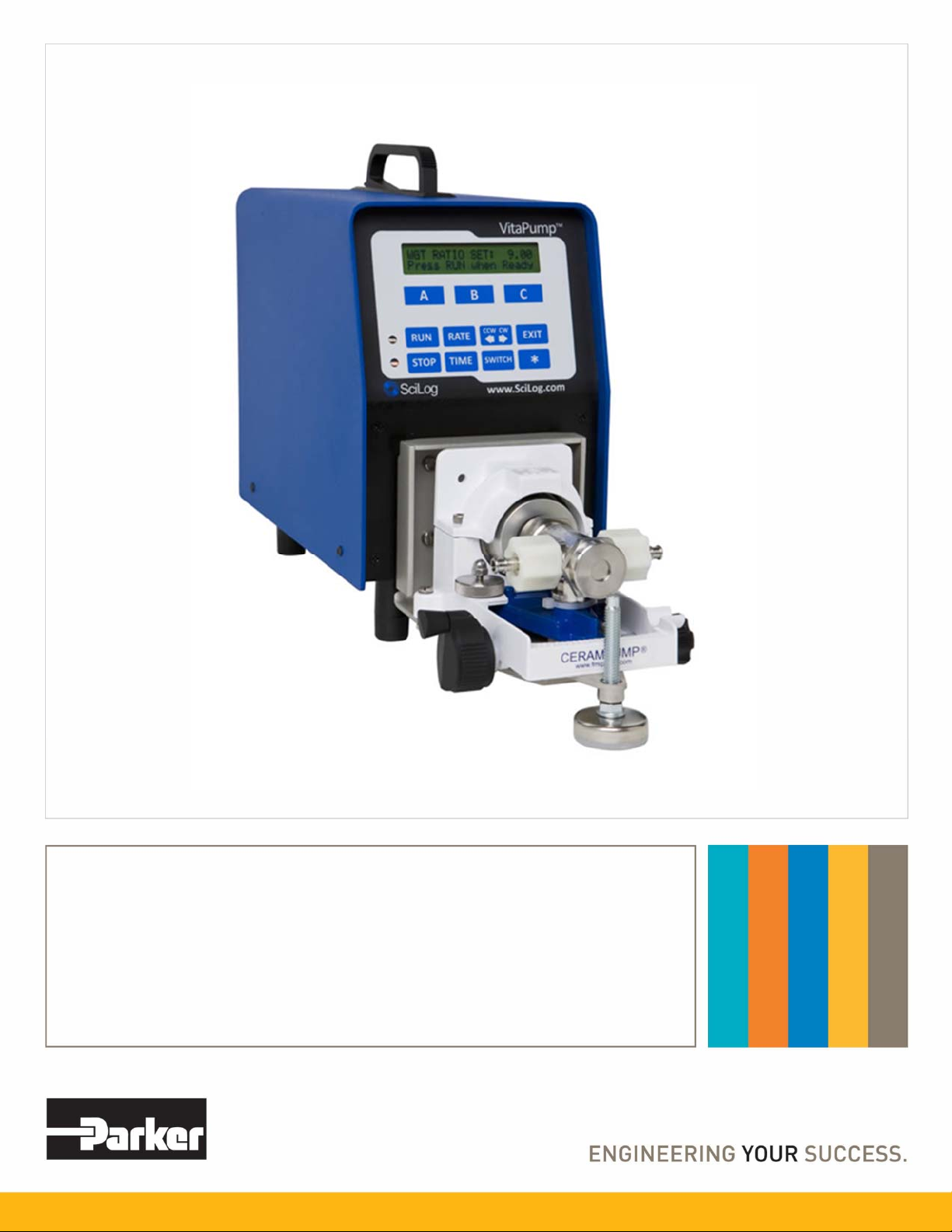
a. Vitamin Metering: Exec/Edit, Section 7.0, Pg. 19
PUMP/MASS RATE: Defines the weight to be metered in grams/minute. For
example, if you want to meter 10.00 gm/min, use the “Incr” and “Decr” keys to scroll
to 10.00 and press “Select”. (The default PUMP/MASS RATE=0.79 gm/min)
DIRECTION: Defines the rotation of the pump head, this parameter can be changed
from clock-wise (CW) to counter clock-wise (CCW). (Default = CW)
b. Vitamin Metering: Alarms, Section 8.0, Pg. 20
All the Alarms have 3 options: “Off”, “Beep Only”, and “Pump Stop”. “Off” disables
the alarm. “Beep Only” gives an audible alarm and continues pumping. “Pump Stop”
gives an audible alarm and stops the pump. Use Pump Stop for all critical alarms.
When the pump rate alarm is activated, the pump is running at 100%. After pressing
any key to disable the alarm, you must press EXIT, and then Exec to re-enter the
metering program.
ALARM: PUMP RATE: The VitaPump will maintain the pump rate based on
feedback from the balance. When it is unable to maintain the rate (E.G. when the
vitamin reservoir is empty), it will increase its speed to compensate. If it reaches
100% of motor speed for 30 seconds, it will activate the pump rate alarm. This is
considered a critical alarm, and should be set to “Pump Stop” to avoid over/under
fortification.
ALARM: WEIGHT ALARM: Allows the setting of a Batch Weight to provide an alarm
when the set weight is reached. Generally used as a warning that a bottle of vitamins
is nearly empty. When used, which is extremely rare, the usual setting is “Beep
Only”. (Default = Off)
ALARM: BATCH WEIGHT: If Weight Alarm above is enabled enter a Batch Weight
here. This is usually set to the weight of a full bottle minus 5%.
ALARM: INTERUPT: The Interrupt alarm is triggered when the VitaPump has been
in a self-paused state for more than 2 minutes. This usually occurs when the scale
has been interfered with (more vitamins poured into the bottle) while the scale is in
use! Options: OFF Beep Only, and Pump Stop. This is normally a critical alarm, and
should be set to PUMP STOP.
2. For this example, use the default pump rate of 6 gm/min. Press the EXIT key on the front
panel until you reach the Mode Select screen. From the Mode Select screen, use “A” or “B”
to go up or down to the “Metering” mode. You will see following display:
Mode Selct METERING
Up Down Select
A B C

10
3. Press “C” to select, and the following screen is displayed:
-
V
ITAMIN D -
Exec Edit Alarm
A B C
4. At this point, you may press “C” again to enter the “ALARM” submenu and configure them
as discussed above. You may also press “B” to enter the Edit Menu to change the flow rate
or the pump direction. When ready, press “A” to Execute the program, and the display will
show the following:
↓
5. Press the “RUN” key on the front panel, or close the flow control switch in your process, and
the VitaPump will Tare the scale and begin metering. The following is displayed:
↓
PR PUMP RATE (grams/minute).
TW TOTAL WEIGHT (kilograms). This a long-term cumulative weight, designed for weekly,
monthly, or longer recording of vitamins dispensed. It should only be reset with a
supervisor’s approval.
BW BATCH WEIGHT (kilograms). This weight is reset every time the metering program is exited
and re-executed, i.e. when the vitamin bottle is changed.
NOTE: The Remote On/Off connected to your PLC flow control switch will only have an effect on
the pump when the “Press RUN When Ready” screen is displayed, or the pump is actually
metering. This requires a contact closure (CC), i.e. a solenoid or solid-state switch.
PR = 6.00 g/m RUN
TW = 0000.000 BW = 0.000
REMOVING TARE WEIGHT
Please Wait
VITAMIN D: 6.00 g/m
Press RUN When Ready
SCALE INITIALIZATION
Please Wait

11
Printer Documentation:
The VitaPump will output data to a printer at periodic intervals for archival purposes. The following
is an example of that data, and an explanation of the abbreviations used. A slightly different form of
PC output is available, see Section 5.2 PC Control, Commands & Data of the VitaPump manual for
an example.
VITAMIN D = 6.00g/m: ALARMS: BW=2; PR=3; LIMIT:BW=0.000kg
T= 00.00
;
TW = 0.000k
g;
BW = 0.000k
g;
PR =6.00
g
/m ST=START
T= 00.05; TW = 0.030k
g
; BW = 0.030k
g
;PR =6.00
g
/m ST=RUN
T= 00.10; TW = 0.060k
g
; BW = 0.060k
g
;PR =6.00
g
/m ST=RUN
T= 00.15; TW = 0.090k
g
; BW = 0.090k
g
;PR =6.00
g
/m ST=RUN
T= 00.20; TW = 0.120kg; BW = 0.120kg; PR = 6.00g/m ST=STOP AL = PR
T= 00.21; TW = 0.120kg; BW = 0.120kg; PR = 6.00g/m ST=EXIT
VITAMIN D = Several different labels available to choose from under Mode:Setup, SET LABEL.
T TIME: Relative time counter, starts/resets at beginning of batch metering program. Can be
set to actual time, and print the current date in header. See example below.
TW TOTAL WEIGHT, long term cumulative counter, can be reset in Mode:Setup, CLEAR
TOTAL.
BW BATCH WEIGHT, cumulative batch weight counter, resets at beginning of batch metering
program, usually when new vitamin bottle is placed on balance.
PR PUMP RATE, gravimetric metering rate expressed in grams/minute ST = STATUS, Pump
Status (Start, Run, Pause, Run, Exit)
AL ALARM, Print out of Alarm condition. AL=PR represents Pump Rate Alarm, AL=BW
represents Batch Weight Alarm. AL=BI represents the Interrupt Alarm.
NOTE: Three alarm levels are defined and displayed in the program header of the printout as
follows: 1 = Off (Deactivated); 2 = Alert (Metering continues, auditory beep/5V output to remote
alarm occurs); 3 = Pump Stop (Stops the pump, auditory beep/5V output to remote alarm occurs).
Immediate data printout occurs when RUN, STOP or EXIT keys are pressed, and when an alarm
occurs. All other printouts occur at a user definable frequency in hours:minutes. (Mode:Setup,
Printer, Time)
If you choose to do so, you can go to Mode:Setup, Clock and enter the Time of Day (24hr format),
Day, Month, and Year. Under Mode:Setup, Clock, Print Enable, select Time of Day instead of
Relative Time. The data printout will change to look like the
following, and drastically ease your
record keeping:
VITAMIN D = 6.00g/m: ALARMS: BW=2; PR=3; LIMIT:BW=0.000kg 10/29/02
T= 16:30
;
TW = 0.000k
g;
BW = 0.000k
g;
PR =6.00
g
/m ST=START
T= 16:35; TW = 0.030k
g
; BW = 0.030k
g
;PR =6.00
g
/m ST=RUN
T= 16:40; TW = 0.060k
g
; BW = 0.060k
g
;PR =6.00
g
/m ST=RUN
T= 16:45; TW = 0.090kg; BW = 0.090kg; PR = 6.00g/m ST=RUN
T= 16:50; TW = 0.120k
g
; BW = 0.120k
g
;PR =6.00
g
/m ST=STOP AL = PR
T= 16:51; TW = 0.120kg; BW = 0.120kg; PR = 6.00g/m ST=EXIT

12
If you purchase a unit equipped with a Tandem 1081 peristaltic head, the following chart shows
tubing dimensions and the available flow rates based on tubing size, and the standard 160rpm
motor:
MasterFlex Tubing 13 14 16 25 17 18
Tubing ID*: in 0.030 0.060 0.125 0.190 0.250 0.310
Tubing OD*: in 0.157 0.189 0.251 0.314 0.376 0.439
Tubing Wall*: in 0.063 0.063 0.063 0.063 0.063 0.063
Pump Rate Range*:
gm/min 0.5 - 10 1.7 - 35.2 6.3 - 129 12.5 - 283 18.5 - 405 24.7 - 554
* Nominal Values
Pump Head Model: TANDEM 1081
CAUTION: The following information should be considered and passed along to the
operators:
1. Changing the vitamin reservoir. DO NOT REPLACE THE VITAMIN BOTTLE WHILE
THE PUMP IS RUNNING, IT WILL STOP!! Always press the EXIT button on the front
panel, change the reservoir, press “A” to execute the program again, and press RUN
when ready. The VitaPump will tare the scale, zero the batch weight, and resume normal
operations. If you are changing the reservoir in response to a Pump Rate Alarm, the
same procedure applies. You do not want to leave the pump running at 100% motor
speed.
2. Remote On/Off. This is generally connected to your flow controller and can work in a
steady state or pulse mode. Under Mode:Setup, Remote On/Off, if you select ENABLE, it
requires a steady state closed or open switch. If DISABLE is chosen, a pulse type signal
(like that generated by pressing and releasing a foot switch) is required. In either case,
this only functions when the pump is metering, or is showing “Press Run When Ready”
on the front panel.
3. SciLog suggests the use of 1/4" ID (#17) tubing for the piston head version, and #14 or
16 tubing, for the peristaltic version dependant upon your flow rates, and that you move
the portion inside the pump 3-4 inches toward the discharge side of the pump
periodically to avoid excessive wear.

13
VitaPump Specifications:
Mechanical:
Dimensions: Width: 5.75 in (14.6cm); Height: 8.5 in (212.6); Depth: 11in (27.9)
Weight: 14 lbs (6.4kg)
Enclosure: Aluminum / Steel; Corrosion Resistant, Recessed Handle.
Pump Head / Motor Options:
1. Tandem 1081 peristaltic pump head with 160-RPM motor, thin-walled (0.060”) pump
tubing: #13 & 14. Flow Range: 0.5 to 45.0 ml/min. max back pressure: 30 psi.
2.FMI Q1 Sanitary Piston head, with 160-RPM motor, Stainless Steel body, Ceramic
Piston and Cylinder. Tubing: #17 Tygon Food Grade, 1/4" ID. Flow Range, 0.5 to 42 ml/min
Electrical:
Power: 90 - 264 V , 47-63 Hz, 150 VA, listed Class 2 switching power supply.
Double fused: 1A-T, 250V (CE: IR35A 250V ).
Battery: CR1220, used to support the internal clock only, not user serviceable.
Motor: Choice of three (3) motors: 8, 160 and 600 RPM at 24V , 3.8 Amperes,
Variable Pump Speed optically encoded servo-controlled motors.
Encoder: 100 lines per / rev. for 600-RPM motor. 120 lines per / rev. for 8 and 160
RPM motors.
I/O Ports:
“Printer”, Female DB9 connector for data collection with Printer or PC.
“S1”, Male DB9 connector for RS-232 connection to an electronic scale.
“S2”, Male DB9 connector, Not utilized on PureTec. Do not remove the cover.
“S3”, Male DB9 connector, Not utilized on PureTec. Do not remove the cover.
“External I/O”, Female DB37 connector used for remote On/Off control of
PureTec via footswitch, or for Analog interface with SciCon or other 4-20 ma
source, A1, A2, A3.
“V”, Female DB15 connector, Not utilized on PureTec.
“Temperature”, 2 pin Conxall connector for SciTemp™ disposable
Temperature Sensor.
“P1, P2, P3”, RJ11 connectors used for SciPres disposable Pressure Sensors.
“USB”, USB-A connector, used for RS-232 data collection with a PC.
“Ethernet”, RJ-45 connector, used for Modbus TCP/IP connection with system.
(when available)
Display: Two line LCD, 20 characters each, back-lit.
Data Entry: Membrane keyboard with auditory feedback.

14
Environmental:
Temperature range: 4 to 40C.
Altitude: up to 2000 Meters
Indoor, dry environments only, clean-up is wipe down only.(IP 20)
Relative humidity: 0-95%
Voltage fluctuations +/- 10%
Pollution degree: 2
Software:
Main menu with the following three (3) operational modes.
Metering Mode: Gravimetric vitamin metering, requires electronic balance. Several
“Labels” available. (i.e. “Vitamin A & D”, “Vitamin A” etc.) Two user-definable alarms.
Setup Mode: Selection of user preferences and interface options.
Manual Mode: Simple pump control (% Speed); no alarms.

15
Part A: Hardware
1.0 VitaPump: Overview
The VitaPump provides high precision, high accuracy, programmable metering capability. The
VitaPump utilizes an optically encoded, servo- controlled motor, ensuring a highly reproducible
pump performance. The VitaPump comes with the TANDEM peristaltic pump head (TANDEM
Model 1081), or an FMI Q1 SAN pump head which is powered by a 160 rpm motor.
1.1 PumpSense™: Pump Overload Protection
When the installed pump head requires excessive torque because of pump tube failure or
“freezing” of the pump head, the VitaPump software will recognize this condition and go into
a stand-by mode. The pump motor is turned off and the following message is displayed:
Before continuing with your pumping application, remove the defective pump head and either clean
the pump head or replace with a functional pump head. The PumpSense feature has been
implemented as a failsafe device to protect your pump head and motor control circuit from
permanent damage.
NOTE: Call Parker Customer Service at 805-604 to arrange for service if the “Check Your Pump
Head” message does not disappear after the above suggested measures have been taken.
Pump tubing can become frayed when overused. When this happens, the pump tubing tends to
wind itself around the pump rotor: To avoid this problem, check your pump tubing at regular
intervals, move the used tube section 3-4 inches to the pump discharge side. Use only high quality,
correctly sized pump tubing.
1.2 Pump Head/Motor:
The VitaPump comes with a 160 rpm, optically encoded, servo-controlled motor and a TANDEM
Dual Channel Peristaltic Pump Head. Materials of Construction: Stainless Steel and Noryl high
impact resistant plastic, four (4) roller design (stainless steel). Passive pump tube retention, two
stainless steel forks automatically engage pump tubing when the TANDEM pump head is closed.
The TANDEM Model 1081 (P/N: 080-1081) is compatible with thin-walled (0.062”) Masterflex pump
tube sizes 13, 14, 16, 25, 17 & 18.
If you have a system with backpressure in excess of 30 psi, the VitaPump is available with an FMI
Q Sanitary Piston Pump. This pump head will handle up to 100 psi, and is constructed of 316 SS
and Ceramic parts. It handles similar flow rates to the Tandem 1081 head, and is equipped for ¼”
ID tubing.
CHECK YOUR PUMP HEAD
Press Any Key

16
2.0 Front Panel: Data Entry & Display
The front panel consists of a user interface, which includes an alphanumeric display and a
membrane keypad to select operational modes and alarm settings. The display is a two line, 20
characters each, liquid crystal display (LCD). The display is backlit to allow easy viewing over a
wide range of lighting conditions.
The lower line on the LCD is used to signify the function of the “soft keys” marked “A”, “B” and “C”.
The “soft key” current labels are displayed in the lower line of the LCD. If you press these keys,
then the function displayed above it is performed.
The main keypad consists of eight “hard” keys whose function does not change. These keys are
used for basic control and programming of the VitaPump. The basic key definitions are:
Executes the selected operational mode and starts pump.
Interrupts current operational mode and stops pump.
Sets pump Rate in gm/min, depending on Mode being implemented.
Has no function on the VitaPump
Pump direction, counter-clockwise or clockwise. (CW or CCW Command)
Has no function on the VitaPump.
Used to Exit current operational mode or menu level, stops pump and exits the
mode.
Has no function on the VitaPump.
Two LED’s are also on the front panel, just to the left of the main keypad. These
indicate the current pump status. A green light indicates the pump is in
motion; the red light indicates that the pump has stopped.

17
3.0 Back Panel: Interface Options
The VitaPump back panel provides interfacing ports for:
Printer Port: The VitaPump can be connected to a PC for data collection or to a Parker
Printer via the female DB9 RS-232 port labeled “Printer”. You need a Parker RS-232 cable
(P/N 080-073) to connect to a PC for data archival, or a printer cable (080-096) to make the
connection between the printer and the VitaPump.
Electronic Balance: Male DB9, labeled “S1”. (S2 and S3 are not utilized.)
Alarm / Remote Start – Stop Cable Set: (PN 080-074) Male DB37, Labeled “External I/O”.
See explanation on the next page.
SciPres Disposable Pressure Sensors: Three RJ11 telephone jacks, one for each
pressure sensor. Labeled “P1, P2, P3”. Not utilized by the VitaPump.
SciTemp Disposable Temperature Sensor: Conxall 2 pin connector. Labeled
“Temperature” Not utilized by the VitaPump
Scale Ports: The male DB9 ports labeled “S1”, “S2” and “S3” are RS-232 ports for
electronic scales. For the VitaPump, only S1 is used. This port allows the user to interface
with a number of different electronic scales: i.e. Mettler, Ohaus, and Sartorius top-loading
scales. The following scale cables are required:
Mettler ICS425 Series: PN: 080-072ICS
Mettler: PGS, PM, Viper Models P/N: 080-067PGS
Ohaus: Adventurer (Pro) Series P/N: 080-067PGS
Sartorius: Most Series Balances P/N: 080-068
In VitaPump: Setup: Scale, select the scale manufacturer; the VitaPump will automatically
implement the correct communications parameters. Check that the proper
communications parameters are also implemented in the scale being used.
Valve V Port: not utilized by the VitaPump.

18
USB Port: Used for connection to a PC, providing a Com Port. Can be used for data
collection as an alternative to the Printer port. The driver is included on the CD that contains
this manual.
Ethernet Port: Disabled.
3.1 External I /O Port: A TTL alarm output (two-wire cable between pin 9 and pin 30) allows you
to monitor VitaPump alarm conditions. (5.0VDC output control signal, requires use of a solid state
relay that will trip at 3 volts; is low (0 volts) when off, and high (5 volts) when tripped.
An additional TTL output will provide you with a similar signal to provide a Status Signal that is On
(5 volts) when the VitaPump’s motor runs, and Off (0 volts) when it isn’t. (two-wire cable between
pins 12 & 31) (5.0VDC output control signal, requires use of a solid-state relay that will trip at 3
volts)
A TTL input (two-wire cable between pin 19 and pin 37) allows remote “RUN” / “STOP” by means of
dry contact closure. This last feature is set to LEVEL (contact closure) by default for input from your
control system. It can be set to PULSE to allow use of the RUN button in Metering Mode.
All three cables are usually assembled as a set into one head shell and tested at Parker prior to
shipment.

19

20
Part B: Software
1.0 Main Menu
VitaPump Main Menu
On power-up the VitaPump will perform a scale initialization to confirm that the balance is properly
connected and responding to the VitaPump. The power-up- display will prompt you to press the
“RUN” key to start vitamin metering using the last metering rate set.
If instead, you press the “EXIT” key twice, you will reach the Main Menu above. The Main Menu
consists of three (3) operational modes: METERING, SETUP, and MANUAL. You can use the “Up”
and “Down” keys to scroll through the menu.
Press the “Select” key to enter the first sub level menu, and the “Exit” key again to return to the
previous level.
METERING Mode allows you to set the Pump Rate and Direction, as well as configure both the
Pump Rate Alarm and the Batch Weight Alarm.
SETUP Mode is used to configure the Scale, Clock, Printer, Pump, Serial Mode, External Run-Stop,
Set Label, and Clear Total parameters.
MANUAL Mode allows the VitaPump to be operated manually. You can select pump speeds from
0 – 100% of motor speed. In Manual Mode, gravimetric (with a balance) metering is not possible.
Table of contents
Other Parker Laboratory Equipment manuals
Popular Laboratory Equipment manuals by other brands

Tuttnauer
Tuttnauer 6690 STS-1V Operation & maintenance manual

Scienceware
Scienceware Colony Counter instructions

SCI
SCI LSCF user manual

Agilent Technologies
Agilent Technologies Triple Quadrupole LC/MS user guide

PSC
PSC PowerScan Quick reference guide

Konica Minolta
Konica Minolta DRYPRO 832HG specification

H.E. Anderson
H.E. Anderson Feeder J Plus Installation Guidelines and Operation

Biotage
Biotage TurboVap 96 Dual Installation and safety

IonOpticks
IonOpticks Aurora Series user guide

Xylem
Xylem SI Analytics TITRONIC 500 operating manual

Soilmoisture Equipment
Soilmoisture Equipment 1768B-.15SYS1 quick start guide

Kodak
Kodak Dryview 5800 user guide