Parker PICOSPRITZER III User manual

Parker Hannifin
Precision Fluidics Division
45 Route 46 East
Pine Brook, NJ 07058
973-575-4844
http://www.parker.com/ppf
PICOSPRITZER® III Manual
Pressure Systems for Ejection of
Picoliter Volumes in Cell Research

http://www.parker.com/ppf
Page 2
PICOSPRITZER III
SAFETY
Please read this entire set of instructions before attempting to use this manual for intracellular or extracellular
ejections. This instrument should only be used as specified by the manufacturer. Use other than as specified
may present a safety hazard. It is intended for research purposes only. Not for use on humans or for
diagnostic purposes.
There are no user serviceable parts inside the instrument. Please consult the manufacturer before removing
the cover as hazardous voltages may be exposed. Use only the electric cord supplied with the instrument or
one of equal capacity.
For continuing safe operation of the unit periodic inspections of the connections in the pressure system should
be made to ensure they are all still tight, particularly after a period of inactivity or if the system is moved.
This instrument is intended for use in an indoor environment between 10 and 40 degrees Celsius (50 to 104
degrees Fahrenheit) with no more than 90% humidity (non-condensing).
EQUIPMENT SPECIFICATIONS
Power Requirements: 100 to 240 Volts AC
50 to 60 HZ
0.8 Amps @ 115 Volts AC
0.6 Amps @ 230 Volts AC
Fuses: 1 Amp, 250 Volts, Slow Blow
5 X 20 millimeters
Maximum Inlet Pressure: 150 PSIG Clean, dry gas
Do not use oxygen, corrosive, or combustible gas
Environmental: Temperature: 10 C (50 F) to 40 C (104 F)
Humidity: 90% non-condensing
Altitude: 0 to 2000 meters
Overvoltage: Category II
Pollution: Degree 2
The instrument is equipped with a universal power supply which will operate on the full range of voltages
between 100 and 240 volts AC.

http://www.parker.com/ppf
Page 3
Contents
SAFETY....................................................2
EQUIPMENT
SPECIFICATIONS...................................2
INTRODUCTION.....................................3
OPERATING SPECIFICATIONS............4
CONTROLS AND USE............................4
BACKGROUND.......................................7
PICOSPRITZER® III MODELS..............11
PICOSPRTIZER® III
Pressure Systems for Ejection of
Picoliter Volumes in Cell Research
OPERATING MANUAL
I. INTRODUCTION
Please read this entire set of instructions before
attempting to use this instrument for
intracellular or extracellular ejections. These
instructions cover all currently produced systems
(single channel and two channel models).
The Picospritzer III is a self-contained, rack-
mountable system which supplies repeatable pressure
pulses. Volumes dispensed are linear with time and
pressure. The system can be initiated three ways:
front panel push button, external stimulator (5 volt),
or remote push button/foot pedal. The Picospritzer III
pressure system was designed for rapid and
reproducible ejections of picoliter to nanoliter
volumes used in conjunction with intracellular or
extracellular studies while avoiding the inherent
desensitization of nerve cells which accompanies
Iontophoretic methodology.
Intracellular applications range from femtoliter
ejections of RNA into small (50m diameter) cells to
nanoliter ejections into oocytes. Extracellular
applications range from picoliter applications of
dilute neuroactive substances onto neurons during
intracellular recording to the presentation of chemical
stimuli to whole animals.
The system comes complete with high speed valve(s)
and the necessary tubing assemblies (less pipette and
holder). It is designed to fit a standard 19" relay rack.
The Picospritzer III comes fully adjusted and ready to
use.

http://www.parker.com/ppf
Page 4
II. SETUP INSTRUCTIONS
1. Position the control unit in the desired location.
Position the remote valve box within two feet of the
experimental site (VELCRO® is supplied for
mounting) and within 6 feet of the control unit.
2. Connect the black ¼ inch pressure tubing to the
side port on the front panel regulator and to a
source of clean dry compressed gas (air, nitrogen,
CO2, or argon) at a maximum of 150 PSI (10bar).
DO NOT USE OXYGEN OR COMBUSTIBLE
GASES. The fitting on the regulator is a quick-
connect type. The end of the tubing should be cut
cleanly and inserted fully into the opening in the
fitting. An o-ring seals around the outside of the
tube. To remove the tubing from the fitting you
must first vent the pressure from the line then press
the ring on the end of the fitting (around the tubing)
toward the body of the fitting while pulling on the
tubing.
3. Use the 6-foot long 1/8-inch tubing assembly to
connect the front panel regulator to the remote
valve box. The connection at the regulator is also a
quick-connect type while that to the remote valve
box is threaded (1/4-28 male). There should be a
ferrule pressed in to this end of the tubing.
4. The 3-foot long 1/16-inch tubing assembly is
used to connect the remote valve box to a pipette
holder (optional). Both ends of this assembly have
¼-28 nuts and ferrules pre-assembled on it.
PLEASE NOTE: An important detail in arranging
the location of the solenoid in relation to the pipette
holder is to maintain a loose coil in the
interconnecting small bore (1/16 inch) Teflon®
tubing to absorb or dampen the pressure pulse, thus
avoiding movement of the pressure pipette. DO
NOT stretch the tubing out tight between the valve
housing and the pipette holder.
II. OPERATING SPECIFICATIONS
Standard Pressure Range:
10-100 psig, self-bleeding pressure regulator
Optional Pressure Range:
3-25 psig, self-bleeding pressure regulator
Pulse Durations:
3 to 999 milliseconds, 1 ms intervals
0.1 to 99.9 seconds, 0.1 sec. intervals
0.1 to 99.9 minutes, 0.1 min. intervals
Pulse Initiation Trigger:
Pushbutton on panel, remote pushbutton/footswitch,
or external stimulator (5 volt TTL input BNC jack).
Time Mark Output:
5-volt TTL signal from front panel BNC jack.
References channel one output.
External Inputs:
5-volt TTL input BNC jack per channel.
Remote Valve Box:
24 volt DC high speed enclosed solenoid valve.
III. CONTROLS AND USE
The unit is activated when the power switch is in the
ON position and the red pilot light is on. The unit
must be connected to a source of clean, dry
compressed gas at a pressure at least as high as that
desired for ejections. Clockwise rotation of the
knurled knob on the right of the rack mount panel
will increase the pressure (indicated on adjacent
gauge) available for injection purposes. This unit
contains a self-bleeding regulator so that the pressure
may be reduced by simply rotating the pressure
control knob counter-clockwise.

http://www.parker.com/ppf
Page 5
The system is rated to operate up to 100 PSI (6.7
bar). One can be assured that all the connections are
gas-tight by rotating the knob on the front panel so
that the meter indicates approximately 80 PSI of
pressure and then shutting off the main source of
pressure to the panel. If a gradual reduction of
pressure is observed, it indicates that there is a leak
somewhere between the remote valve housing and
the main pressure source. The site of this leak may
be found by carefully listening for a hissing sound
or by application of a dilute soap solution (or
“snoop”) and watching for the formation of bubbles
at various connections. It is essential to have leak
proof connections throughout the system to assure
reproducible results and to avoid unnecessary loss
of gases.
Volume ejected is a linear function of both pulse
duration and pressure (see references 1, 3). The
pulse duration has a greater dynamic range with
more accurate and reproducible settings. Thus,
pulse duration will be changed frequently during
the course of the experiment while pressure settings
will be changed relatively little on a daily basis.
DURATION SETTING
The pulse duration is indicated by the setting on the
three digit thumbwheel switch and the extended
range switch (see Extended Range). It may be
initiated by pressing the adjacent button on the
front panel, by remote push button, or by an
external input signal. The circuit has a “debounce”
control which restricts the action of the push button
so that only one pulse is initiated per button press,
even if the button is continuously held down. It also
restricts the interval between repetitive pulses
initiated by the push button to approximately 200
milliseconds. The “PULSE” indicator will light
during the course of the pulse.
EXTENDED RANGE
The basic Picospritzer is furnished with extended
range timing controlled by a three- position toggle
switch located at the right side of the “Duration”
thumbwheel. The top position (labeled “MSEC”),
selects timing in the milliseconds range (2 to 999
milliseconds). In the center position (labeled “SEC”),
the range is from 0.1 to 99.9 seconds (note the
decimal). In the bottom position (labeled “MIN”), the
range is from 0.1 to 99.9 minutes.
INDICATORS
The Picospritzer III contains four LED indicators.
“ON” is the power indicator. The “PULSE” indicator
shows that the timer is active; the channel 1 and
channel 2 indicators show when each channel is
active.
INPUT TRIGGER
The internal timer now has a separate BNC jack to
allow it to be triggered from an external source. A
low to high (+5 volts) transition on this BNC will
trigger the internal timer just as if the manual
pushbutton had been pressed. If a pulse train is
applied to this jack, care should be taken to ensure
that the duration setting is less than the period of the
pulse. Otherwise pulses will be skipped.
REMOTE PUSH BUTTON
A jack on the front panel of the Picospritzer is
provided for attachment of an optional remote push
button or foot pedal for initiating a pulse. This
convenience permits the investigator to be some
distance from the rack mount panel and to view an
ejection through a microscope while initiating the
ejection. When using a remote push button, the
button has the same function as the panel push
button. Optional hand or foot activated switches are
available. Refer to Picospritzer Accessories list for
additional information.

http://www.parker.com/ppf
Page 6
EXTERNAL INPUT
For additional flexibility in experimental use, the
Picospritzer III has a front panel BNC jack for each
channel which permits independent activation of
the two channels from external sources. The
selector toggle switch above each jack determines
the source of the control signal for that channel. In
the “EXTERNAL” position, it operates by
energizing the valve whenever the input signal
is high (+5 V.D.C.) and de-energizes it when the
signal returns to ground. This allows for pulse
durations longer than the capacity of the internal
timer. In the “TIMER” position, the channel is
connected to the internal timer and will activate
whenever that timer is triggered (either manually or
externally).
SECOND CHANNEL
The Picospritzer III is equipped with a separate
BNC jack and selector toggle for each of the two
channels. This allows 2 external signals to be used
to operate the 2 channels independently when the
selector toggles are set to the “EXTERNAL”
position. Placing a selector toggle to the “TIMER”
position connects that channel to the internal timer
for operation whenever the timer is triggered (either
manually or externally). To prevent a channel from
triggering, place the selector switch in the
“EXTERNAL” position and do not make a
connection to the BNC for that channel.
All Picospritzer III's are designed with second-
channel capability.
MARKER
The time mark provides a convenient indication of
the duration of the pulse with respect to a biological
signal much like that of the “artifact” associated
with iontophoresis. It is a 5-volt TTL signal
controlled by channel one. The time mark not only
provides a useful indication of the duration of the
pulse, but it may also serve as a sync-out signal for
triggering the sweep of an oscilloscope, etc.
HOLDERS FOR PRESSURE PIPETTES
Standard pipette holders are available for pipettes
with diameters of 1.0, 1.2, 1.5 and 2.0 mm.
For prices and dimensions, see the Picospritzer
Accessories list.
No internal adjustment of the Picospritzer should be
undertaken by the user without consulting the
manufacturer. Detailed instruction will be provided
if necessary.
PICOSPRITZER III FAQ
(Frequently Asked Questions):
1. I used to purchase the vacuum loading unit is that
still available?
Currently, the vacuum loading unit is no longer
available for purchase
2. I used to purchase a 0-10 or 0-60psi regulator, are
those options still available?
Currently, we no longer offer the 0-10 or 0-60psi
regulator, only configurations listed on page 11 are
currently available
3. If I purchase a two channel unit, can I trigger the
two channels independently using two separate
footswitches or push buttons?
Currently, the Picospritzer III can only handle one
footswitch or push button (the footswitch and push
button control the internal timer). You can trigger
them independently using an external trigger. Please
see Second Channel section to the left.
4. If I purchase a two channel unit can, I provide
separate pressures to the two valve boxes?
Currently, the Picospritzer will only provide the same
pressure to both valve boxes.

http://www.parker.com/ppf
Page 7
IV. BACKGROUND
In 1977, Dr. R.E. McCaman and associates
provided a complete description (1) of a pressure
ejection system that utilized a high speed valve.
This valve continues to be the heart of the pressure
system offering very precise control of ejection
volumes (in the picoliter range) and ejection times
(in the millisecond range).
Furthermore, these investigators described a series
of holders that permitted ejection through
micropipettes with sufficiently small tips that could
be used for simultaneous intracellular recordings
during ejections.
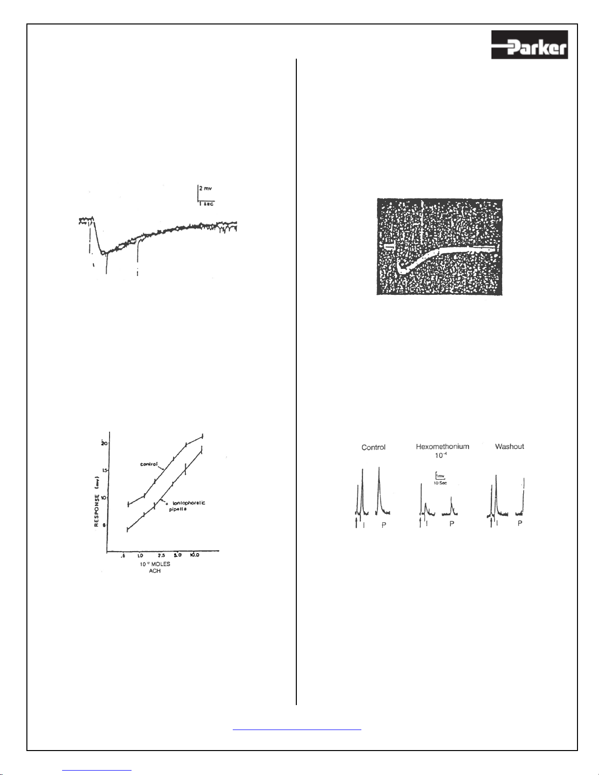
These systems have been used for intracellular as
well as extracellular ejections. In listing advantages
of the pressure system, these investigators
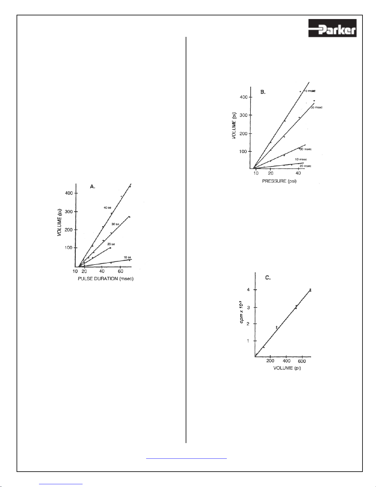
emphasize that the linear relationship between
ejection volume and either duration of the pulse or
of the applied pressure permits a rapid, convenient
and reliable calibration of each pipette (1, 3), unlike
that for electrophoretic techniques (7-9).
Pressure ejection seems an ideal approach to
delivering uncharged substances such as peptides
(4, 6), steroids (4), and enzymes (2,5). The
solutions used for pressure ejections are usually
several orders of magnitude more dilute than those
used for electrophoretic ejection (1, 3), thus
avoiding receptor desensitization commonly
experienced with iontophoresis. The fact that the
ejection efficiency of the pneumatic systems is not
influenced by solute concentration nor by net
charge, makes them ideal for intracellular injections
of radiolabeled or tracer substances (13-15).
Thus, pressure systems have been used for
intracellular injection of radiolabeled precursors or
neurotransmitters (10, 11) and [H3] –sugars as
precursors of glycoproteins (12) in order to study
neuron-specific transmitter biosynthesis, axonal
transport and cellular topography. The reproducible
and quantifiable ejections obtained with pressure
systems make them ideal for neuropharmacological
studies of agonist and drug interactions with
membrane receptors (1, 3, 4).
As you find additional uses for your Picospritzer,
please send us a reprint for addition to our reference
section so that others may benefit from your
experience.
N.B.; H3=radioactivity (tritium) label substance.
REFERENCES
References describing the use and unique advantage
of pressure systems in several types of
experimentation in the field of neurobiology, cell
biology, and biophysics are:
1. McCaman, R.E., Mc Kenna, D.G. and Ono, J.K.
“A pressure system for intracellular and extracellular
ejections of picoliter volumes.” Brian Research
136:141 (1977).
2. Sakaki, M., Sakai, H. and Woody, C.D.
“Intracellular staining of cortical neurons by pressure
micro-injection of horseradish peroxidase and
recovery by core biopsy.” Exp. Neurol. 58:138
(1978)
3. Sakai, M., Swartz, B.E. and Woody, C.D.
“Controlled micro release of pharmacological agents:
measurements of volume ejected in vitro through fine
tipped glass microelectrodes by pressure.”
Neuropharmacol. 18:209 (1979)
4. Dufy, B., Vincent J-D. Fluery, H., Pasquier, P.,
Gourdji, D., and Tixler- Vidal, A. “Membrane effects
of thyrotropin-releasing hormone and estrogen shown
by intracellular recording from pituitary cells.”
Science. 204.509 (1979)
5. Tauc, L., Hoffman, A., Tsuji, S., Hinzen, D. and
Faille, L. “Transmission abolished in a cholinergic
synapse after injection of acetylcholinesterase into
the presynaptic neuron.” Nature, 250, 496 (1974)
6. Chang, J.J., Gelperin, A., and Johnson, F.H.
“Intracellulary injected aequorin detects
transmembrane calcium flux during action potentials
in an identified neuron from the terrestrial slug.”
Brain Research 77:431 (1974)

http://www.parker.com/ppf
Page 8
7. Krnjevic, K., Mitchell, J.F., and Szerb, J.C.
“Determination of iontophoretic release of
acetylcholine from micropipettes.” J.Physiol.
165:421 (1963)
8. Zieglgansberger, W., Southmann, G., and Herz,
A. “Iontophoretic release of substances from
micropipettes in vitro.” Neuropharmacol. 13:417
(1974)
9. Kuffler, S. and Yoshikami, D. “The number of
transmitter molecules in a quantum: an estimate
from iontophoretic application of acetylcholine at
the neuromuscular synapse.” J. Physiol. 251:465
(1975)
10. Eisenstadt, M., Goldman, J.E., Kandel, E.R.,
Koike, H., Koester, J. and Schwartz, J.
“Intrasomatic injection of radioactive precursors for
studying transmitter synthesis in identified neurons
of Aplysia.” Proc. Nat. Acad. Sci. 70:3371 (1973)
11. Schwartz, J.H. “Synthesis, axonal transport and
release of acetylcholine by identified neurons of
Aplysia.” Proc. Nat. Acad. Sci. 70:3371 (1973)
12. Thompson, E.B., Schwartz, J.H. and Kandel,
E.R. “A radio autographic analysis in the light and
electron microscope of identified Aplysia neurons
and their processes after intrasomatic injection of
L-H3-Fucose.” Brain Research.112:251 (1976)
13. Baux, G., Simonneau, M. Tauc, L. “Transmitter
release, Ruthenium red used to demonstrate a
possible role of sialic acid containing substrates.” J.
Physiol. 291, 161-178 (1979)
14. Sakai, M., Sakai, H., and Woody, C.D.
“Sampling distribution of morphologically
identified neurons of coronal- pericruciate cortex of
awake cats following intracellular injection of
HRP.” Brain Research. 152: 329-333 (1978)
15. Amaral, D.G. and Price, J.L. “An air pressure
system for the injection of tracer substances into
the brain.” Jrnl. Neuroscience Methods. 9:35-34
(1983)
FIGURE 1
DROPLET CALIBRATION CHART
Calibration chart provided courtesy of Dr. Joyce K.
Ono, Department of Biological Science, California
State University

http://www.parker.com/ppf
Page 9
FIGURE 2
CHARACTERISTICS OF THE PRESSURE
EJECTION SYSTEM
The diameter of the droplet ejected in air was
measured with an ocular micrometer in a dissecting
microscope. The volume was calculated for
droplets formed by varying pressure or pulse
duration parameters. The following graphs
demonstrate that each pipette can be calibrated by
varying these two major determinants of the
volume ejected.
FIGURE 2A: LINEARITY OF VOLUME
EJECTED WITH VAYRING PULSE
DURATION AT CONSTANT PRESSURE
The X-intercept (15 MSEC) represents the
mechanical lag time of the particular solenoid
valve.
FIGURE 2B: LINEARITY OF VOLUME
EJECTED WITH VARYING PRESSURE AT
CONSTANT PULSE, DURATION
The X-intercept (7.5PSI) represents the minimum
pressure necessary for ejection and is a characteristic
of a particular pipette
FIGURE 2C: LINEARITY OF THE AMOUNT
OF AN H3 STANDARD WITH VARIOUS
EJECTED VOLUMES
The points of this graph are highly correlated (R=.97)
with the independently determined specific activity
(6.5 x 10⁶ CPM/mL) of the radioactive solution.

http://www.parker.com/ppf
Page 10
FIGURE 3
COMPARISONS OF RESPONSES OF
APLYSIA CALIFORNICA NEURONS TO
IONTOPHORETIC AND PRESURE
APPLICATION OF COMPOUNDS
FIGURE 3A:
Superimposed traces of Aplysia buccal neuron
responses to ACh delivered by an iontophoretic
pulse (1µ amp, 80 MSEC) and a pressure pulse (40
PSI, 60 MSEC, 60 µm diameter droplets of 10-3 M
ACh). The amplitude and polarity of the pressure
artifacts (negative square pulse in this case) can be
manipulated.
FIGURE 3B:
Comparisons of responses to pressure ejected
acetylcholine (ACh) in Aplysia neuron in the
absence (control) and presence of an iontophoretic
pipette (70 MEGOHMS) containing 1 M ACh. The
dose-responsive curve is shifted to the right
because of desensitization from ACh leaking out of
iontophoretic pipette. Each point is the mean
response + standard error of the mean.
Problems of desensitization can be circumvented
with a pressure pipette since the pipette is usually
filled with agonists in the concentrations of 10-6 to
10-3 M in contrast to iontophoretic pipettes. Braking
current is not necessary for the pressure pipette, thus
avoiding inconsistent ejection of compounds.
FIGURE 3C:
Reproducibility of 12 consecutive responses to
acetylcholine (ACh) delivered by a pressure pulse to
an Aplysia (Sea Hare) neuron. A 10-4M solution of
ACh was ejected by 22 PSI for 5 MSEC to produce a
droplet estimated to be 10 PL (=1 Femtomole of
ACh). Calibration: 2 mV, .02 Sec.
FIGURE 3D:
Comparison of response to iontophoretic (I) and
pressure (P) applied ACh in a drug study. Both
responses are equally antagonized by
hexamenthonium, even though the ACh in the
pressure pipette is ejected in a droplet of normal
artificial seawater. Similar results are obtained during
substitution experiments. The arrows in the figure
point to an input resistance test pulse.

http://www.parker.com/ppf
Page 11
PICOSPRITZER® III MODELS
SINGLE CHANNEL UNITS
P/N 051-0500-900
0-100 PSI regulator
P/N 051-0530-900
0-30 PSI regulator
TWO CHANNEL UNITS
P/N 052-0500-900
0-100 PSI regulator
P/N 052-0530-900
0-30 PSI regulator
PICOSPRITZER REPLACEMENT / SPARE
PARTS
VALVE BOX & CABLE ASSEMBLY
P/N 051-0009-401-1
TEFLON® TUBING ASSEMBLIES
P/N 039-0125-062-72
1/8 inch OD tubing, 6 feet long, nut & ferrule on
one end.
P/N 035-0125-062-72
1/8 inch OD tubing, 6 feet long, nut & ferrule on
both ends.
P/N 035-0062-032-36
1/16 inch OD tubing, 3 feet long, nut & ferrule on
both ends.
REPLACEMENT GASKETS
P/N 050-00XX-GSK-KIT*
*XX should be replaced by your Pipette’s OD.
Example: P/N 050-0010-GSK-KIT is for a 1.0 mm
pipette holder. Each Kit comes with 10 replacement
gaskets and 1 replacement nut.
PICOSPRITZER® ACCESSORIES
Pushbutton & Cable Assembly
P/N 050-0000-800-1
Footswitch & Cable Assembly
P/N 050-0000-801-1
PIPETTE HOLDERS
P/N 050-00XX-110-1*
Standard Straight Holder with a 0.080 inch diameter
by 1.5 inch long mounting rod
P/N 050-00XX-130-1*
Standard Straight Holder with a .186 inch diameter
by 3.5 inch long mounting rod
*XX is replaced by the Pipette’s OD. We have 1.0, 1.2,
1.5 and 2.0mm options available
(Example: P/N 050-0010-110-1 is for a
1.0mm OD pipette)

http://www.parker.com/ppf
Page 12
PICOSPRTIZER® III
Pneumatic assembly
Note: Single channel and vacuum loading models have only one valve box and the “tee” fitting is omitted.
PICOSPRTIZER® III MODELS
A. Single Channel (Basic Model): The PICOSPRITZER III comes complete except for pipettes and pipette
holders. One valve box and cable is supplied as well as the tubing required to connect it to the front panel
mounted regulator assembly and to a pipette holder. 12 feet of ¼ inch OD tubing are supplied to make the
connection between the regulator assembly and the compressed gas supply (maximum 150 psig). Expansion
capability for a second valve box is built in.
B. Two Channel: This PICOSPRITZER uses the same electrical chassis as the single channel but
includes two valve boxes and the tubing assemblies to connect both to the front panel regulator and to pipette
holders (pipettes and holders are not included).
Table of contents
Other Parker Laboratory Equipment manuals