Parker 8903/IM User manual

Cont.1
8903/IM and 8903/IP
Ethernet Communications
Interfaces
Technical Manual
HA500522U001 Issue 2
Compatible with 890 Firmware Version 3.2 onwards
Copyright 2008 Parker SSD Drives, a division of Parker Hannifin Ltd.
All rights strictly reserved. No part of this document may be stored in a retrieval system, or transmitted in any
form or by any means to persons not employed by a Parker SSD Drives company without written permission
from Parker SSD Drives, a division of Parker Hannifin Ltd . Although every effort has been taken to ensure the
accuracy of this document it may be necessary, without notice, to make amendments or correct omissions.
Parker SSD Drives cannot accept responsibility for damage, injury, or expenses resulting therefrom.
WARRANTY
Parker SSD Drives warrants the goods against defects in design, materials and workmanship for the period of 12
months from the date of delivery on the terms detailed in Parker SSD Drives Standard Conditions of Sale IA500504.
Parker SSD Drives reserves the right to change the content and product specification without notice.

Cont.2
WARNING!
During commissioning, remove the fuses (or trip the circuit breaker) on your 3-
phase supply.
Make sure the power is OFF, and that it cannot be switched on accidentally whilst you
are working.
REFER TO YOUR MAIN PRODUCT MANUAL FOR SPECIFIC SAFETY
INFORMATION ABOUT THE DEVICE YOU ARE CONTROLLING
IMPORTANT: Please read this information BEFORE installing the equipment.
Intended Users
This manual is to be made available to all persons who are required to install, configure or
service equipment described herein, or any other associated operation.
The information given is intended to highlight safety issues, EMC considerations, and to enable
the user to obtain maximum benefit from the equipment.
Application Area
The equipment described is intended for industrial motor speed control.
Personnel
Installation, operation and maintenance of the equipment should be carried out by qualified
personnel. A qualified person is someone who is technically competent and familiar with all
safety information and established safety practices; with the installation process, operation and
maintenance of this equipment; and with all the hazards involved.
Safety
All control and signal terminals are SELV, i.e. protected by double insulation.
EMC
In a domestic environment this product may cause radio interference in which case the user may
be required to take adequate counter-measures.
This equipment contains electrostatic discharge (ESD) sensitive parts. Observe static control
precautions when handling, installing and servicing this product.
Safety Information
!

Cont.3
CAUTION!
At any time, there may be a loss of motor control and separate/independent application
measures should be taken to ensure that such loss of motor control cannot present a safety
hazard.
RISK ASSESSMENT
Under fault conditions, power loss or unintended operating conditions, the drive may not
operate as intended. In particular:
•Stored energy might not discharge to safe
levels as quickly as suggested, and can still
be present even though the drive appears to
be switched off
•The motor's direction of rotation might not
be controlled
•The motor speed might not be controlled
•The motor might be energised
A drive is a component within a drive system that may influence its operation or effects under
a fault condition. Consideration must be given to:
•Stored energy •Supply disconnects •Sequencing logic •Unintended
operation
Safety Information
!

Contents
Contents Page
Cont.4
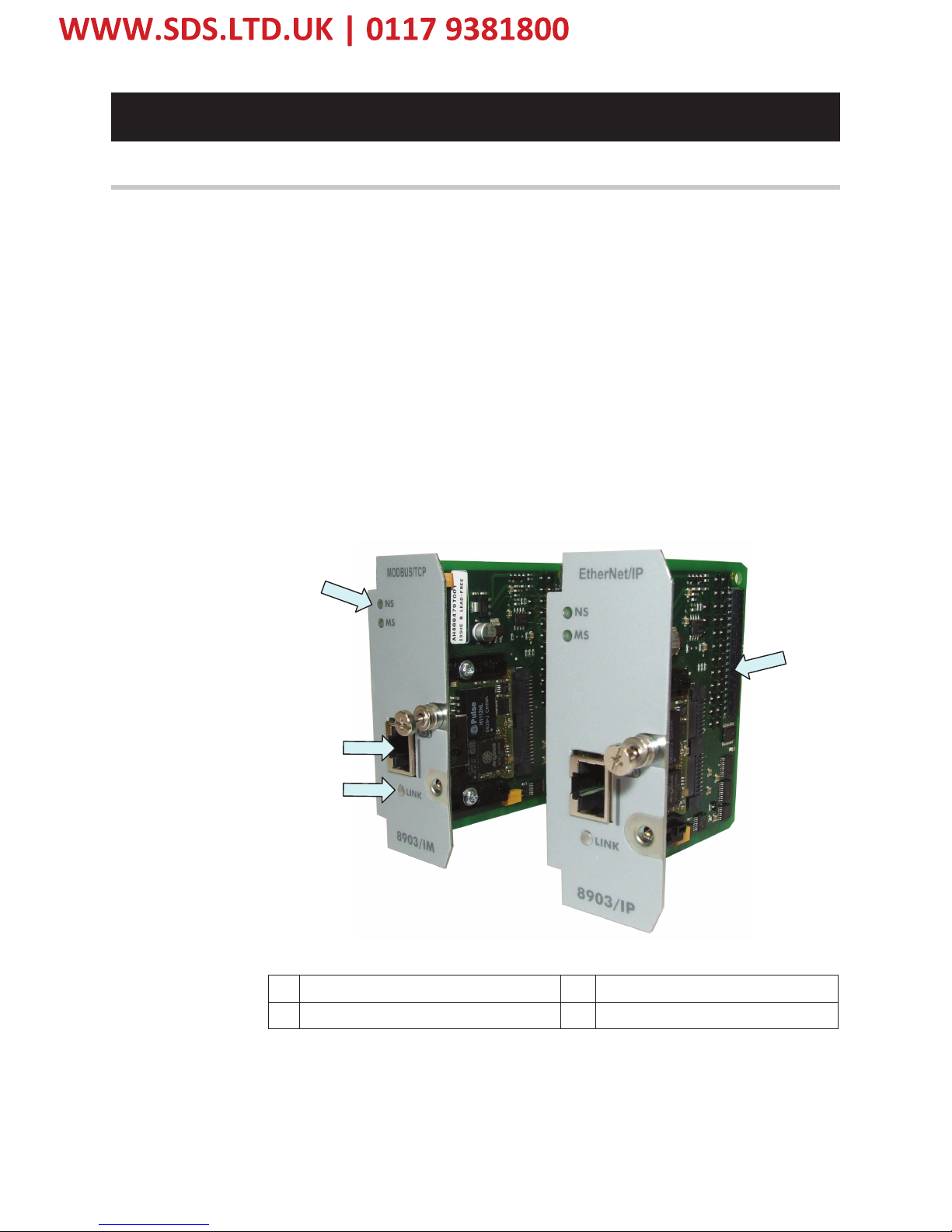
ETHERNET COMMUNICATIONS INTERFACE 1
Introduction ..................................................................................................... 1
Product Features ........................................................................................................ 1
Product Codes ........................................................................................................... 1
Installation....................................................................................................... 2
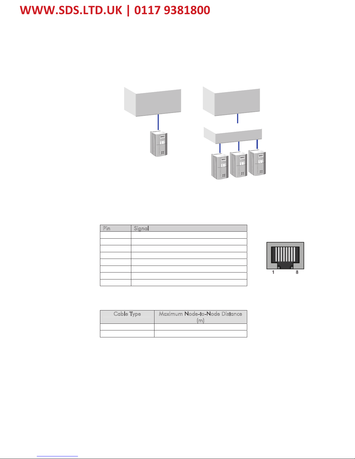
Wiring the System ...................................................................................................... 5
LED Indications ................................................................................................ 6
Network Status LED (NS)............................................................................................. 6
•Modbus/TCP ........................................................................................... 6
•Ethernet/IP .............................................................................................. 6
Module Status LED (MS).............................................................................................. 7
•Modbus/TCP ........................................................................................... 7
•Ethernet/IP .............................................................................................. 7
LINK/Activity LED........................................................................................................ 7
Drive Diagnostics............................................................................................. 8
•The Ethernet MMI View............................................................................. 8
•Parameter Descriptions ............................................................................ 8
Configuring the Ethernet System..................................................................... 9
Step 1: Configuring the Ethernet TechCard using DSE 890........................................... 9
•Step 1.1: Inserting an Ethernet Function Block ........................................... 9
•Step 1.2: Attaching Fieldbus Connectors ................................................. 10
•Step 1.3 : Configuring the Fieldbus Connectors....................................... 11
•DSE Data Types ..................................................................................... 13
•Ethernet Data Types ............................................................................... 13
•Conversion of DSE Type < > Ethernet Type ............................................ 13
Step 2: Configuring the PLC/SCADA Supervisor......................................................... 14
•Modicon Momentum.............................................................................. 14
•Allen Bradley ControlLogix ..................................................................... 16
•TS8000 Operator Station using DSI8000 ................................................ 18
Configuring DSE to Connect over Ethernet .................................................... 22
Appendix A: Ethernet Error Codes................................................................. 23
Appendix B : DSE/Ethernet Conversion Rules ............................................... 29
•LOGIC Type Connector ......................................................................... 29
•INTEGER Type Connector....................................................................... 29
•VALUE Type Connector .......................................................................... 30

1
8903/IM 8903/IP Ethernet Communications Interfaces
ETHERNET COMMUNICATIONS INTERFACE
Introduction
This manual describes the Parker SSD Drives' Ethernet Communications Interface Options
(TechCards).
Product Features
•Available for 890 products
•Easy plug-in installation
•Suitable for use with drive models:
890CD Common Bus Drive and 890SD Standalone Drive
using 890 firmware version 3.2 onwards
•Galvanically isolated bus electronics
•10/100Mbit operation
•LEDs to indicate network and module status
•Supports Modbus/TCP protocol (8903/IM only)
•Supports Ethernet/IP protocol (8903/IM only)
•Supports RTNX protocol to connect to Drive System Explorer
1 NETWORK and MODULE status LEDs 3 LINK Activity LED
2 RJ45 Ethernet Interface 4 Connector to Control Board
Product Codes
Part Number: 8903/IM/00 – Ethernet Modbus/TCP TechCard
8903/IP/00 – Ethernet/IP TechCard
Figure 1. Ethernet TechCard
1
4
3
2

2
8903/IM 8903/IP Ethernet Communications Interfaces
Installation
WARNING!
Before installing, ensure that the
drive wiring is electrically isolated
and cannot be made “live”
unintentionally by other personnel.
Wait 5 minutes after disconnecting
power before working on any part of
the system or removing the covers
from the drives.
To Remove the Control Board
1. Remove the blank covers, each secured
by a single screw, that fit over the
TechCard holes.
2. Loosen the top and bottom screws in
the handles of the Control Board (2).
3. Pull gently on the handles and slide the
Control Board (2) out of the drive.
Note: Save the blank cover and screw for
future use. The drive should not be
operated without a TechCard or blank
cover. When fitted, these maintain the
drive's IP20 rating.
Figure 3. Front of 890 drive showing
Control Board fitted
Figure 2. 890 showing Control Board
withdrawn, with Options fitted
3
2
1
1
2

3
8903/IM 8903/IP Ethernet Communications Interfaces
Fitting the TechCard
The TechCard fits onto the Control Board.
1. Insert the connector into the TechCard as shown. The legs of the connector will protrude
through into the connector on the other side of the TechCard.
2. Press the assembly into the TOP connector (adjacent to terminals X10, X11 and X12) on
the Control Board. Ensure that the front panel of the TechCard overlaps the front of the
Control Board. Ease the connector at the TechCard so that the two pcb's are parallel when
viewed on edge.
Figure 4. Fitting the connector to the TechCard

4
8903/IM 8903/IP Ethernet Communications Interfaces
Re-fitting the Control Board
1. Slide the board into the drive, engaging the edges of the boards into the slots. Push until the
back edge of the Control Board pcb locates with the connectors in the drive.
2. Tighten in position using the top and bottom screws in the blue handles of the Control
Board.
3. Screw the TechCard in position using the captive screw on the front of the TechCard.
Figure 5. 890 Control Board with TechCard fitted

5
8903/IM 8903/IP Ethernet Communications Interfaces
Wiring the System
Connection to the drive(s) from a PC, or PLC for example, is made using a cable fitted with
standard RJ45 connectors at both ends. The cable plugs into the PLC, for example, and into the
socket on the Ethernet techbox.
Note: When connecting to one drive direct from PC/PLC, you must use a crossover cable.
RJ45 (Standard) Pin Details
Pin Signal
1 TD+
2 TD-
3 RD+
4 Termination
5 Termination
6 RD-
7 Termination
8 Termination
Cable Specifications
Cable Type Maximum Node-to-Node Distance
(m)
CAT5 100
CAT5E 100
PLC
PLC
Switch/Hub
Figure 6. Typical connections to a PLC

6
8903/IM 8903/IP Ethernet Communications Interfaces
LED Indications
Network Status LED (NS)
Note: A test sequence is performed on this LED during start-up.
Modbus/TCP
Colour LED Indication Description
OFF OFF No power or no IP Address set
GREEN ON Normal operation
GREEN FLASHING Waiting for connections
RED
ON
Duplicate IP Address
Figure 7. Modbus/TCP NS LED
Ethernet/IP
Colour LED Indication Description
OFF OFF No power or no IP Address set
GREEN ON On-line, one of more connections
established
GREEN FLASHING On-line, no connections established
RED
ON
Duplicate IP address
RED FLASHING One or more connections timed out
Figure 8. Ethernet/IP NS LED

7
8903/IM 8903/IP Ethernet Communications Interfaces
Module Status LED (MS)
Note: A test sequence is performed on this LED during start-up.
Modbus/TCP
Colour LED Indication Description
OFF OFF No power
GREEN ON Normal operation
GREEN FLASHING Major fault
RED
ON
Duplicate IP Address
RED FLASHING Minor fault
Figure 9. Modbus/TCP MS LED
Ethernet/IP
Colour LED Indication Description
OFF OFF No power
GREEN ON Controlled by a Scanner in Run state
GREEN FLASHING Not configured, or Scanner in idle
state
RED
ON
Major fault
RED FLASHING Recoverable fault(s)
Figure10. Ethernet/IP MS LED
LINK/Activity LED
Colour LED Indication Description
OFF OFF No link, no activity
GREEN ON Link established
GREEN Flickering Activity
Figure 11. LINK/Activity LED

8
8903/IM 8903/IP Ethernet Communications Interfaces
Drive Diagnostics
The Ethernet MMI View
Diagnostic information is available through the MMI.
MMI Menu Map
1 SETUP
2 COMMUNICATIONS
3 ETHERNET
RTNX IP ADDRESS
890 IP ADDRESS
890 SUBNET MASK
890 GATEWAY
Parameter Descriptions
RTNX IP ADDRESS Read Only Range: NOT CONNECTED,
XXX.XXX.XXX.XXX
The IP Address of the computer running Drive System Explorer (DSE) is displayed if
connected to the 890 via Ethernet.
If DSE is not connected, then NOT CONNECTED is displayed. Note – this is also
displayed if there has been no communications activity from the connected DSE in the
last 5 minutes.
890 IP ADDRESS Read Only Range: XXX.XXX.XXX.XXX
IP Address of the 890.
890 SUBNET MASK Read Only Range: XXX.XXX.XXX.XXX
Subnet Mask being used.
890 GATEWAY Read Only Range: XXX.XXX.XXX.XXX
Gateway Address being used.

9
8903/IM 8903/IP Ethernet Communications Interfaces
Configuring the Ethernet System
To configure the Ethernet system, complete the steps below.
Step 1: Configuring the Ethernet TechCard using DSE 890
Step 1.1: Inserting an Ethernet Function Block
Display your configuration page. Click on the Block menu at the top of the screen.
1. Move the cursor down to select "890 Comms" and select "Ethernet".
2. Click to attach the block icon to the cursor. Move the icon to where you want on the screen.
Click again to release the icon.
Figure 12. Configuration showing EN Function Block

10
8903/IM 8903/IP Ethernet Communications Interfaces
Step 1.2: Attaching Fieldbus Connectors
Seven fieldbus connector types are available:
FB Logic Input FB Integer Input FB Value Input
FB Logic Output FB Integer Output FB Value Output
FB Val to Int Output
Input connector : the data is sent from PLC ¤890
Output connector : the data is sent from 890 ¤PLC
The fieldbus connectors must be added before they will appear in the EtherNet function block.
Note: The function block and connectors can be renamed by using the right mouse button and
selecting Rename Block.
Figure 13. Configuration showing EN Function Block and Fieldbus Connectors

11
8903/IM 8903/IP Ethernet Communications Interfaces
Step 1.3 : Configuring the Fieldbus Connectors
Double-click on the function block to display the dialog below. The fieldbus connectors (inputs
and outputs) are assignable in the function block along with their data type to/from the PLC.
The Option Slot, 32-bit Order, IP Address, Subnet Mask and Gateway Address can also be
selected.
To configure the input and output connectors you have placed in the configuration:
1. Expand the Inputs and Outputs trees to reveal the registers. By default the trees each have
one register. To add more registers click on adjacent to New…
2. Select the drop-down menu in the Input column to choose the required input/output
connector on the Register. For example below, Register 1 "Input" is shown with the
possible fieldbus selections that have been placed in the configuration: FII.1 (Fieldbus
Integer Input 1), FLI.1 (Fieldbus Logic Input 1), FVI.1 (Fieldbus Value Input 1) etc.

12
8903/IM 8903/IP Ethernet Communications Interfaces
3. Select the drop down menu in the Type column to choose the required PLC type on
Register 1, for example.
4. Set up all the input/output registers in a similar way.
5. Set up the option parameters:
"Option Slot" = A (top). The Ethernet TechCard can only be fitted in the OPTION A slot of
the drive. This is the default setting for "Option Slot".
“32bit order” is set to either “Low Word First” or “High Word First”. This refers to how
32-bit data types, i.e. SINT32, UINT32 and FLOAT are encoded on Ethernet. If Ethernet/IP
is being used, this should always be Low Word First. If Modbus/TCP is being used, it
depends on the master.
•Low Word First is sometimes referred to as “Modicon Mode” and is used when the
least significant 16-bits are sent in a lower register number than the most significant
16-bits, i.e. Little-endian.
•High Word First is sometimes referred to as “IEEE Mode” and is used when the most
significant 16-bits are sent in a lower register number than the least significant 16-bits,
i.e. Big-endian.
“IP Address”, “subnet mask” and “gateway” are used to set the IP parameters. If set to
0.0.0.0 they may be configured over Ethernet, e.g. by using the Address Resolution
Protocol (ARP).
Remember:
♦The order and size of the inputs in the DSE Ethernet configuration MUST match the
order and size of the outputs from the PLC configuration.
♦The order and size of the outputs in the DSE ControlNet configuration MUST match
the order and size of the inputs to the PLC configuration.

13
8903/IM 8903/IP Ethernet Communications Interfaces
DSE Data Types
Data Type Description Range
LOGIC Logic False (F) and True (T)
INTEGER 32-bit signed integer -2,147,483,648 to 2,147,483,647
VALUE 32-bit fixed point value -32768.0 to 32767.9999
Ethernet Data Types
Data Type Description Range Bytes Used
SINT16 16-bit signed integer -32,768 to 32,767 2
SINT32 32-bit signed integer -2,147,438,648 to
2,147,483,647
4
UINT16 16-bit unsigned integer 0 to 65,535 2
USINT32 32-bit unsigned integer 0 to 4,294,967,295 4
FLOAT 32-bit IEEE-754 floating-point
value
1.19209290e-38 to
3.4028235e+38
4
Conversion of DSE Type < > Ethernet Type
The DSE fieldbus connectors are each assigned an Ethernet "Type" as described in "Step 1.3 :
Configuring the Fieldbus Connectors" on page 11.
The conversion between the DSE type and the PLC type is performed automatically (refer to
Appendix B : DSE/Ethernet Conversion Rules, page 29).
Any PLC type can be assigned to a fieldbus connector.

14
8903/IM 8903/IP Ethernet Communications Interfaces
Step 2: Configuring the PLC/SCADA Supervisor
This section contains examples for configuring a Modicon PLC, an Allen-Bradley PLC and the
TS8000 Operator Interface. The Ethernet Technology Box supports the ModBus/TCP protocol
and the Ethernet/IP protocol.
Modicon Momentum
1. Start a new program and select
the PLC processor and chassis
type used in your project. Our
example uses an M1 980-20
Momentum PLC. Stay offline
until you are ready to
download the program.
2. Place an MSTR block in the
ladder logic. MSTR blocks
move data from the PLC data
table to the drive or from the
drive to the PLC data table.
Two MSTR blocks are
necessary for a Read and Write
operation.
3. Right click over the MSTR
block. This will access the
Register Editor. Use the
Register Editor to configure
the block. The MSTR block
has two types of operations:
Read or Write. The first
register defines the type of
operation. In our case address
40100 is used for write
command and address 40200 is
used for read command. A
value of 1 in the data column
defines a Write operation. A
value of 2 in the data column
defines a Read operation.
Figure 14. PLC Ladder Logic
showing MSTR Blocks
Figure 15. Read Registers

15
8903/IM 8903/IP Ethernet Communications Interfaces
4. The second register contains the error status. Refer to Appendix A for a list of the error
codes. The PLC software also has help files that contain a list of error codes.
5. The third register defines the data length (address 40102 or address 40202). The value
in the data column depends on which parameter set that has been selected in the drive.
The value can be smaller than or equal to the selected parameter set.
6. The fourth register defines the Read and Write locations of the data in the PLC (address
40103 or address 40203). For a Read function, this value is set to 1, and for a Write
function this value is set to 257.
7. Registers 5, 6, 7 and 8 define the IP address on the Ethernet network (address 40104 or
address 40204). Our example shows the data registers starting at locations 40150 and
40250.
8. When using a Modicon PLC, the “32bit Word Order” parameter in the Ethernet
function block must be set to “Low Word First”. This applies to Modicon products and
most other manufactures using the ModBus/TCP protocol.
Figure 16 Write Registers

16
8903/IM 8903/IP Ethernet Communications Interfaces
Allen Bradley ControlLogix
9. Start a new program and select the PLC processor and chassis type that is used in your
project. Our example uses a 1756-L55A processor and 1756-A7/B rack. Remain Offline
until you are ready to download the program.
10. Using the I/O Configuration insert the Ethernet interface that will be installed. Right click
on the I/O Configuration, select New Module. Our example uses 1756-ENBT/A. Input the
desired IP address and slot in the PLC. Refer to Figures 17 and 18.
Figure 17. Ethernet Interface Selection
Figure 18. Ethernet Interface Setup
This manual suits for next models
1
Table of contents
Other Parker Recording Equipment manuals