Parker L5353 User manual

Copyright Parker SSD Drives, Inc 2008
All rights strictly reserved. No part of this document may be stored in a retrieval system, or transmitted in any
form or by any means to persons not employed by a Parker SSD group company without written permission
from Parker SSD Drives Inc.
Although every effort has been taken to ensure the accuracy of this document it may be necessary, without
notice, to make amendments or correct omissions. Parker SSD Drives cannot accept responsibility for
damage, injury, or expenses resulting therefrom.
Technical Manual
HA470380 Issue 4


Please read this information BEFORE installing the equipment.
Intended Users
This manual is to be made available to all persons who are required to install, configure or
service equipment described herein, or any other associated operation.
The information given is intended to highlight safety issues, and to enable the user to obtain
maximum benefit from the equipment.
Application Area
The equipment described is intended for industrial motor speed control.
Personnel
Qualified personnel should carry out installation, operation and maintenance of the
equipment. A qualified person is someone who is technically competent and familiar with all
safety information and established safety practices; with the installation process, operation
and maintenance of this equipment; and with all the hazards involved.
REFER TO YOUR MAIN PRODUCT MANUAL FOR SPECIFIC SAFETY
INFORMATION ABOUT THE DEVICE YOU ARE CONTROLLING
!

System Overview
The PROFIBUS Protocol
Principles of Operation
I/O Data Exchange
Product Features
Product Code
Installation
Wiring the System
Cable Specification
Grounding the Shield
Terminating Resistors
Terminal Block (TB1) Connections
Fitting the Profibus LinkCard
Installing the Profibus LinkCard
Wiring Diagram
Understanding the LED Indications
Initial Check for Connection
Network and Module LED Indications
Programming Considerations
!" # " $ %
Programming Considerations
Troubleshooting
Module Status LED
Network Status LED
Technical Specifications &
Environmental
Supply Voltage
Physical

System Overview
Area
Computer
PC/VMECNC Host
DCS
Temp
Controller
I/O Field
Device
Motor
Drives
Trans-
mitter Field
Device
Factory
Level
Cell
Level
Field
Level
MMS, TCP/IP Backbone
PROFIBUS-FMS
PROFIBUS-DP PROFIBUS-PA
PLC
PC
Figure 1 PROFIBUS Application Areas
The PROFIBUS Option supports the PROFIBUS-DP variant of the
PROFIBUS protocol, which is designed especially for communication
between automatic control systems and distributed I/O at the device level. It
is most often used to allow a central Programmable Logic Controller or PC
based control system to use external ‘slave’ devices for I/O or specialized
functions. The principal advantage is that these devices may be distributed
around a machine, thereby saving on the cost of point-to-point wiring. The
‘open’ nature of the network also permits equipment from different
manufacturers to be mixed on the same bus. Additionally, the off-loading of
complex and specialized tasks such as PID temperature control lessens the
processing load on the central PLC so that its other functions may be carried
out more efficiently and requires less CPU memory.
The PROFIBUS Protocol
PROFIBUS is a vendor independent, open fieldbus standard for a wide
range of applications in manufacturing, process and building automation.
Vendor independence and openness are guaranteed by the PROFIBUS
standard EN50170. With PROFIBUS, devices from different manufacturers
can inter-communicate. Suitable interfaces exist for PLC’s that include the
Siemens, Mitsubishi and Allen Bradley range.
PROFIBUS-DP (De-central Periphery) is described in DIN 19245 Part 3, and
forms part of EN 50170 with P-Net and WorldFIP. However it is important to
note that P-Net and WorldFIP are wholly incompatible with PROFIBUS,
using different wiring and transmission technologies.
The PROFIBUS-DP network uses a high-speed version of the RS485
standard, permitting baud rates of up to 12Mbaud.
A maximum of 32 PROFIBUS-DP stations (nodes) may be contained within
a single network segment.
PROFIBUS-DP is a multimaster, master-slave, token passing network.
More detailed information, including a detailed guide to products available,
may be obtained from the various worldwide PROFIBUS user organizations.
You will find contact information in trade magazines or by reference to
http://www.profibus.com on the World Wide Web.

!
1. PROFIBUS-PA is designed especially for process automation. It permits
sensors and actuators to be connected on one common bus line even in
intrinsically safe areas. PROFIBUS PA permits data communication and
power over the bus, using intrinsically safe, 2-wire technology according
to the international standard IEC 1158-2, but may also be used on the
standard RS485 cabling for non-intrinsically safe applications.
2. PROFIBUS-FMS is the general-purpose solution for communication
tasks at the cell level.
Principles of Operation
Input Output
Physical I/O
Ladder
Program
PLC I/O Mapping
Slave 1 Slave 2 Slave 3
PLC
Physical
Actuator 1
Figure 2-1a: Plant wiring
conventional comms. systems
I/O scanning
Physical
Actuator 2
Physical
Actuator 3
Physical
Actuator 4
I/O
Mod-
ules
Input Input
Output Output
Slave 4
Figure 2 PROFIBUS compared with conventional communication
systems
PROFIBUS-DP distinguishes between master devices and slave devices. It
allows slave devices to be connected on a single bus thus eliminating
considerable plant wiring typical with conventional communications systems.
The Figure above compares the two systems.
Master devices determine the data communication on the bus. A master
can send messages without an external request when it holds the bus
access rights (the token). Masters are also called active stations in the
PROFIBUS protocol.
Slave devices are peripheral devices. Typical slave devices include
input/output devices, valves, motor drives and measuring transmitters. This
means they will only respond to a master when requested to do so.
PROFIBUS-DP is based around the idea of a ‘cyclical scan’ of devices on
the network, during which ‘input’ and ‘output’ data for each device is
exchanged.

I/O Data Exchange
The process of reading the inputs and writing to the outputs is known as an
I/O data exchange. Typically, the parameters from each slave device will be
mapped to an area of PLC input and output registers or a single function
block so that the controlling ladder logic or program interfaces with the
device as if it were an internally fitted module. It is NOT necessary,
therefore, for the programmer to know anything about the physical network.
The process of network configuration is usually performed using a PC based
program, which allows the devices on the network to be defined and device
parameters to be mapped into the PLC registers or function blocks.
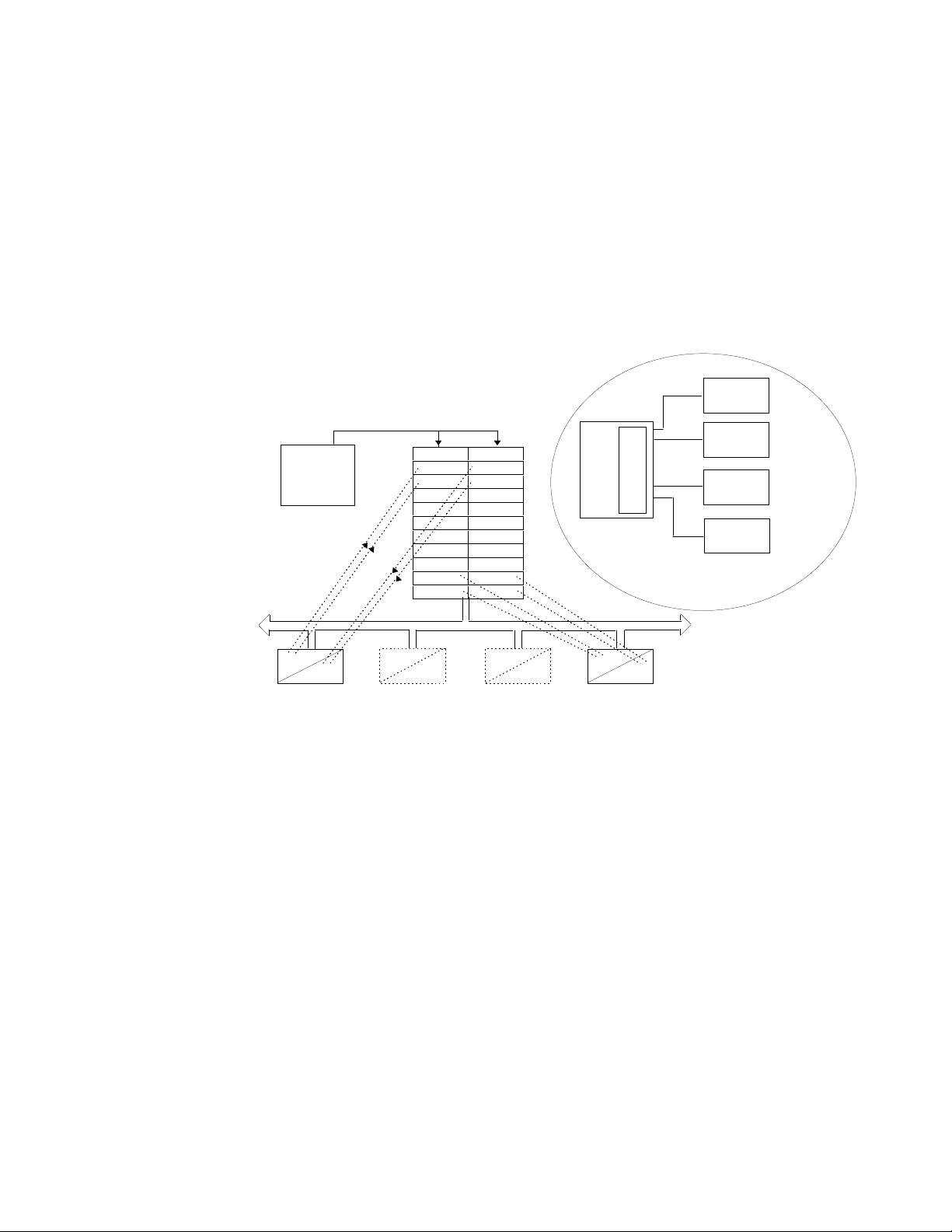
The cyclical scan occurs in the following order:
1. Values from each slave device, ‘Input Data’, are first scanned over the
network into a pre-defined set of input registers in the master controller.
The values might be a set of digital input readings for a digital input unit,
or the measured temperature and alarm status from a PID controller.
2. The master then runs its control program, (such as a ladder logic
program) using the input data read from the slave devices.
3. The master writes output values (output data) into a pre-defined set of
output registers. For example, one of the digital inputs read in the input
data might be used to select one of a set of setpoints to be sent to the
PID controller.
4. These outputs are then written to each slave device, and the scan-
process-write cycle repeats.
Typically no more than 16 bits of input data and 16 bits of output data are
exchanged for each device during the data exchange. The Profibus
LinkCard implementation of the PROFIBUS-DP standard provides the
possibility of transferring 112 words in each direction.
The input and output data lengths for a given device is variable and it is
possible to have devices with only input data, only output data, or both.
The input and output data mixture used by a given slave device is defined by
the GSD file. For simple devices such as digital or analog I/O blocks, it is
fixed. However, since more complex devices often have a much wider
choice of possible values to send, it is usually possible to edit the GSD file to
change the mapping of device parameters into Profibus inputs or outputs.
This is the case with the Profibus LinkCard, which also allows access to
parameter data not in the GSD Input/Output data file.
The GSD file is imported into the PROFIBUS Master Network Configuration
software before the network is created.
Note: PROFIBUS Input Data =Values sent from a slave device to a
master controller or PLC.
PROFIBUS Output Data =Values sent from a master controller or PLC
to a slave device.
DSD viewpoint is looking toward the master controller or PLC.
Profibus Write block is data transfer to the master controller or PLC.
Profibus Read block is data transfer from the master controller or PLC.

Product Features
•Suitable for use with Link modules:
L5392 LinkStation
L5300/1 LinkRack
•Connection using shielded, twisted-pair cable
•LED’s to indicate board and communications status
•Configured using Function Block inputs and outputs
•Diagnostics using Function Block outputs
•Automatic Baud Rate selection
•Software-selectable Slave Address
•112 16 bit words in and 112 16 bit words out
Product Code
The Technology Option is supplied separately.
Part Number: L5353 Profibus LinkCard

"
Installation
Wiring the System
' " () ) * +
Before installing, ensure that the LinkRack wiring is electrically
isolated and cannot be made “live” unintentionally by other personnel.
Wait 5 minutes after disconnecting power before working on any part of
the system or removing the covers from the drives.
The Profibus Option is provided as a plug-in LinkCard.
Note: A 2-wire system can only be used in a network in which all
devices use their tri-state capability. Data flow is restricted; that is,
transmit and receive cannot be simultaneous (half duplex).
Cable Specification
Either of the two cables types detailed below can be used but we
recommend Type A as it allows higher speed and longer cable length.
Type A cable Type B cable
Characteristic
Impedance: 135 to 165Ωat a frequency of 3 to 20MHz. 135 to 165Ωat a frequency of
>100kHz
Cable
capacitance: < 30pF per meter typically <60pF per meter
Core diameter:
Max. 0.34 mm², corresponds to AWG 22 maximum 0.22mm²,
corresponds to AWG24
Cable type: Twisted pair cable. 1x2 or 2x2 or 1x4 lines twisted pair cable. 1x2 or 2x2
or 1x4 lines
Resistance:
< 110Ωper km -
Shielding:
Copper shielding braid or shielding braid
and shielding foil Copper shielding braid or
shielding braid and shielding
foil
Maximum Line Length per Segment
Baud rate (kbit/sec) 9.6 19.2 93.75 187.5 500 1500 12000
Type A cable 1200m 1200m 1200m 1000m 400m 200m 100m
Type B cable 1200m 1200m 1200m 600m 200m - -

#
Grounding the Shield
The PROFIBUS standard suggests that both ends of the transmission line
should be connected to safety earth. If you do this, ensure that differences
in the ground potentials do not allow circulating currents to flow. These can
induce large common mode signals in the data lines and can produce
potentially dangerous heating in the cable. If in doubt, ground the shield at
only one section of the network.
Terminating Resistors
•If the LinkCard is at the end of the network terminating resistors are
required.
•All other Profibus Devices in the system should not have terminators.
Use terminating resistors (Resistors ±5%, ¼ watt or higher) on the
LinkCard.if it is at the end of the Profibus network.
L5353
Profibus
NETWORK
STATUS
MODULE
STATUS
B-B
GND
5Vdc
0Vdc
A-A
RTS
Terminal Block (TB1) Connections
TB1 Terminal Reference Meaning
1 0Vext Signal reference for PROFIBUS
2 +5VDC +5VDC/50mA supply for PROFIBUS
3 B-B’ Receive/Transmit Data Positive
4 A-A’ Receive/Transmit Data Negative
5 RTS For connecting repeater (TTL)
6 GND Ground connection for EMC
+5VDC
B-B
A
-
A
0Vdc
390
Ω
220
Ω
390
Ω

Fitting the Profibus LinkCard
Note: The Profibus LinkCard may be installed into any site (J1, J2, J3,
or J4) of the LinkRack.
' " () ) * +
Ensure that all wiring is isolated.
Installing the Profibus
LinkCard
The Profibus LinkCard
Option plugs into a LinkRack
•Remove the back cover of the LinkRack
•Install the Profibus card into the recess on the back of the LinkRack.
•Re-fit the back cover to the LinkRack
•Make all user-wiring connections. Refer to Wiring Diagram, Figure 3.
L5353
Profibus
NETWORK
STATUS
MODULE
STATUS
B
-
B
GND
5Vdc
0Vdc
A
-
A
RTS

Wiring Diagram
0V
LinkCard
(slave)
PLC/SCADA
(master)
1
2
3
4
5
6
1
2
3
4
5
6
TRANSMIT
A-A'
B-B'
GND
LinkCard
(slave)
last LinkCard in
chain
0V
+5V
B-B'
A-A'
RTS
GND
DC
0V
+5V
B-B'
A-A'
RTS
GND
DC
390
220
screen
connection
390
Ω
Ω
Ω
Figure 3 Typical Wiring Diagram
Note: The diagram above shows the terminal block orientation for the
Profibus LinkCard. When the LinkCard is in place, the terminal order is
effectively reversed - remember this when making user-connections.
Note: The screen connections for the Profibus LinkCard terminate on
the ground connection of the terminal block.

$
Understanding the LED Indications
Initial Check for Connection
With the correct connections to the
active PLC/SCADA supervisor, the
MODULE LED will be ON
continuously and the NETWORK
LED will indicate the Idle State with a
short flash.
Network and Module LED Indications
Network LED
Indicates the state of the
connected network.
Module LED
Indicates the set-up state of the LinkRack Card. The
states indicated are those produced by the FAULT
parameter of the LinkCard function block.
LED Indication Description FAULT Parameter
Description
OFF Disabled or Baud search HARDWARE Not Configured in Link Project or
Hardware Fault - external
FLASH Wait Configuration TYPE
MISMATCH Wrong type or disabled
LONG FLASH Data exchange with error PARAMETER Set-up fault, parameter values out-
of-range
ON Data exchange NONE Valid set-up, ready for external
communications
Note: The NETWORK LED is always in the OFF State when the
MODULE LED is not ON continuously; indicating that the LinkCard is
not receiving external communications or the PLC is off.
ON MODULE LED
SHORT
FLASH NETWORK
LED

Programming Considerations
The maximum amount of either input or output data that will fit in the
DataExchange message is 244 bytes.
The C_PBW and C_PBR blocks each require 16 bytes (8 words). So the
maximum number of each type of block is 15, which is 240 bytes.
If the total number of C_PBW and C_PBR blocks are limited the
maximum to 27 or less, the blocks may be declared in the Profibus
Master individually
Example: either an 8 word input or an 8 word output.
15 Inputs + 12 Outputs = 27 blocks
12 Inputs + 15 Outputs = 27 blocks
14 Inputs + 13 Outputs = 27 blocks
13 Inputs + 14 Outputs = 27 blocks
If the maximum total number of C_PBW and C_PBR blocks is
increased to 28, some of the blocks must declared in the Profibus
Master as 8 word input/output.
Example: input/output blocks
13 Inputs/13 Outputs + 2 Inputs = 28 blocks
13 Inputs/13 Outputs + 2 outputs = 28 blocks
13 Inputs/13 Outputs + 1 Inputs and 1 Output = 28 blocks
Or any other combination that equals 28 blocks

LinkRack Configuration
.Select the L5353 Profibus DP LinkCard.

!
Select Profibus Reader and Writer blocks desired.

Map desired connections to the Profibus Registers
Insert registers into the Profibus Control Block

These inputs
are compiled
to a 16-bit
word for the
PLC.
These inputs
are 16 bit
words within
Link.
Logical to Integer and Value LINK Setup
The above configuration is an example of bit packing into an integer
value.

"
Integer to Logical and Value LINK Setup
The above configuration is an example of bit picking from an integer
value.

#
!" # " $
Programming Considerations
The following considerations should be made while programming the
PLC or Scada Supervisor
The maximum amount of either input or output data that will fit in the
DataExchange message to the L5353 is 244 bytes.
The read and write blocks each require 16 bytes (8 words). So the
maximum number of each type of block is 15, which is 240 bytes.
If the total number of read and write blocks is limited the maximum to
27 or less, the blocks may be declared in the Profibus Master
individually
Example: either an 8 word input or an 8 word output.
15 Inputs + 12 Outputs = 27 blocks
12 Inputs + 15 Outputs = 27 blocks
14 Inputs + 13 Outputs = 27 blocks
13 Inputs + 14 Outputs = 27 blocks
If the maximum total number of C_PBW and C_PBR blocks is
increased to 28, some of the blocks must declared in the Profibus
Master as 8 word input/output.
Example: input/output blocks
13 Inputs/13 Outputs + 2 Inputs = 28 blocks
13 Inputs/13 Outputs + 2 outputs = 28 blocks
13 Inputs/13 Outputs + 1 Inputs and 1 Output = 28 blocks
Or any other combination that equals 28 blocks
Table of contents
Other Parker Recording Equipment manuals