Parker icountPDR User manual

icountPDR
icountPDR User Manual
DD0000002_IPDR_EN_Rev 1
© 2015, Parker Hannifin Corporation
www.parker.com/hfde
GB

GB
2Parker Hannifin icountPDR
Contents
Overview ...................................................................................................3
Conditions for safe use.............................................................................3
Laser Information.....................................................................................3
EC Declaration of Conformity...................................................................4
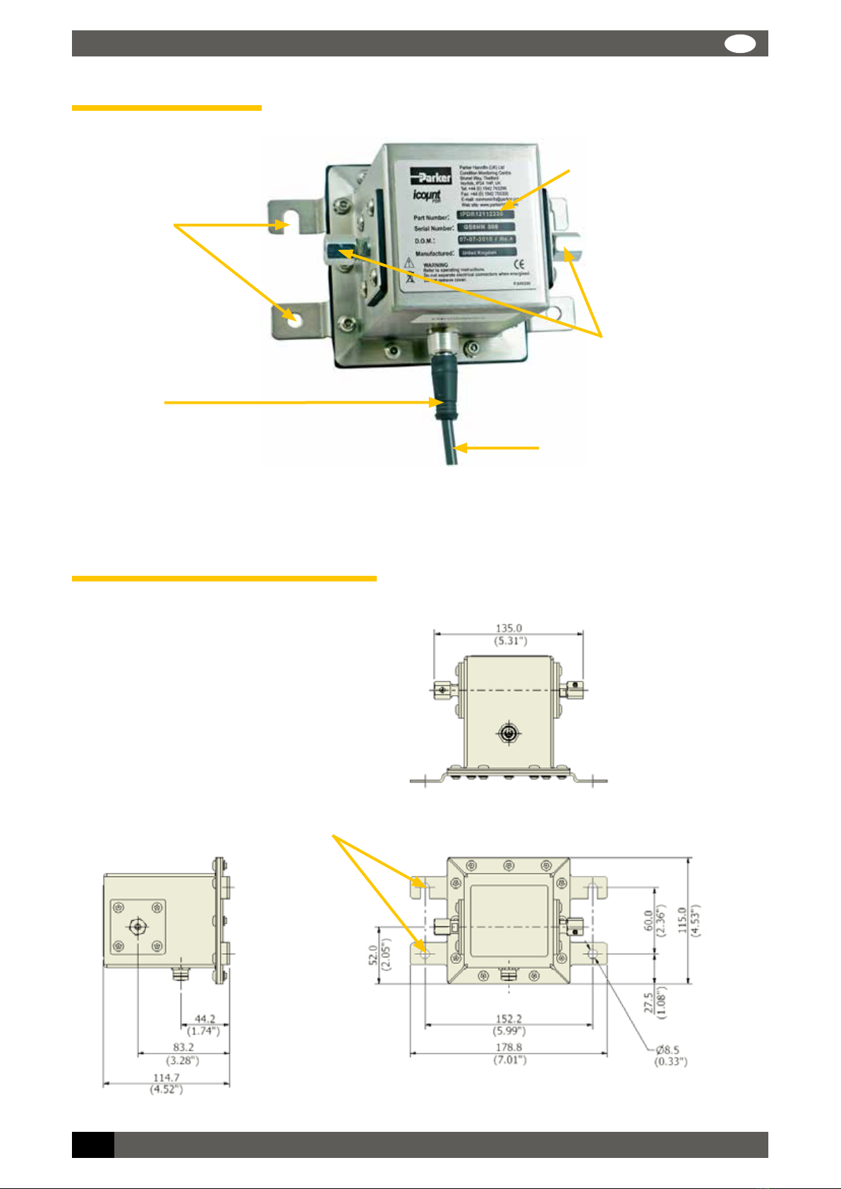
Product identification label ......................................................................5
Introduction............................................................................. 6
Principles of operation .............................................................................6
Benefits.....................................................................................................7
Technical specification .............................................................................8
Software default settings .........................................................................9
Product features.....................................................................................10
Dimensions for installation ....................................................................10
Connections........................................................................... 11
Hydraulic connection..............................................................................11
Flow control............................................................................................12
System 20 sensor connection ................................................................14
Electrical connections ............................................................................15
Variable current output settings ............................................................20
Variable voltage output settings.............................................................21
CAN-bus output option...........................................................................21
Moisture sensor output settings ............................................................21
Digital Display Unit connection ..............................................................22
RS232 connection ...................................................................................24
Software ................................................................................ 25
icountPD Setup Utility software .............................................................25
Microsoft Windows®HyperTerminal connection ...................................28
Communication protocol ........................................................................30
Reference .............................................................................. 35
Contamination Standards.......................................................................35
Viscosity charts.......................................................................................36
icountPD-CAN version, SAE J1939 technical note.................................37
Ordering Information..............................................................................40

Parker Hannifin icountPDR 3
GB
Overview
Parker Hannifin’s icountPDR is an on-line laser particle detector. This mineral based hydraulic fluid
contamination detector is designed for use in robust areas and is housed in a stainless steel IP69
approved enclosure.
The unit has two 06L EO 24° cone-end hydraulic connections (for use with Ø6mm pipe) that allow
fluid to be transferred through the unit for analysis. The electrical supply and communication is
made via an M12 Ultra Lock IP69 approved connector.
Conditions for safe use
Do not open the unit!
To ensure compliance with the certification, users are NOT permitted to open the unit under any
circumstances. Doing so will invalidate the unit’s calibration and it would NOT be suitable for
calibrated use.
‘RH’ limitations
Extended exposure to >90% Relative Humidity causes an irreversible shift in performance. Store the
unit in dry conditions.
Laser Information
This product contains an infrared 5mW laser.
Any dismantling of the product may result in dangerous exposure to laser radiation.
The following laser information is on a label on the top surface of the product:
CAUTION: Users are not required to access the laser radiation source and should never
do so.
The internal laser warning label is mounted on the laser module and contains the following
information:
LASER RADIATION
AVOID EXPOSURE TO BEAM
CLASS 3R LASER PRODUCT

GB
4Parker Hannifin icountPDR
EC Declaration of Conformity

Parker Hannifin icountPDR 5
GB
Product identification label
The identification label attached to the enclosure (an example is given below) is explained in the
table that follows:
Item Field Values
1Part Number icountPDR
2Serial Number The serial number consists of eight digits, for example: GD6NN001
(‘GD’ is the month and year; ‘6NN’ is the product group; the last three digits
are entered sequentially through a month, reverting to ‘001’ at the beginning
of each month)
3D.O.M. Date of manufacture
4Manufactured Country of manufacture (United Kingdom)
5Exclamation mark icon Refer to product manual ‘Safety Recommendations’
6WEEE Disposal icon At the end of life dispose of responsibly, do NOT dispose of in general waste
7Name and address of
manufacturer
Parker Hannifin (UK) Ltd, Filter Division Europe,
Condition Monitoring Centre, Brunel Way,
Thetford, Norfolk, IP24 1HP, UK
8CE Conformity marking and
number of notified body
responsible for audit production
CE 0518
1
2
3
7
8
4
5
6

INTRODUCTION GB
6Parker Hannifin icountPDR
Introduction
Parker Hannifin’s icountPDR represents the most up-to-date technology in solid particle
contamination analysis. The icountPDR is a compact, permanently-mounted laser-based particle
detector module that provides a cost-effective solution to fluid management and contamination
control.
Principles of operation
The icountPDR measures particle contamination continuously and updates the output options and
limit relay every second.
Unlike the Parker CM20, LCM20 or MCM20, the unit does not perform a ‘one-off’ test. This means
that even if the Measurement Period is set to 60 seconds, the output and limit relay all report the
presence of dirt in the oil in just a few seconds – it does not wait until the end of the Measurement
Period before reporting the result.
The icountPDR has just one setting to control the accuracy, stability and sensitivity of the
measurements and that is the ‘Measurement Period’. This can be set from 5 seconds to 180
seconds. The longer the Measurement Period, the more contaminant is measured, averaging out
any spikes seen on a smaller sample. The shorter the Measurement Period, the more sensitive
the icountPDR is to small slugs of contaminant, but it can also reduce the performance on clean
systems. Thus, the user can select how sensitive the icountPDR is to spikes of contaminant, and
how quickly it responds to contamination levels above the set point (‘limits’).
With a Measurement Period of 100 seconds, the results will be for the last 100ml of oil that has
flowed through the icountPDR, updated on a second-by-second basis, giving an effectively
continuous readout of the level of contamination.
Calibration recommendations
NOTE: Any servicing or repair work must be carried out by a Parker approved service
centre. Contact your local Parker Hannifin Sales Company for recalibration details. The
recommended period between recalibration is 12 months.
Please refer to the Parker Hannifin Quality and Servicing Booklet (FDCB272UK), supplied on CD.

INTRODUCTION
Parker Hannifin icountPDR 7
GB
Benefits
Independent monitoring of system contamination trends
Calibration by recognised online principles confirmed by relevant International Organization
for Standardization (ISO) procedures
Indicators for Low, Medium and High contamination levels
A low cost solution to prolonging fluid life and reducing machine downtime
Self-diagnostic software
Mineral fluid-compatible construction
Fully PC/PLC integration technology such as: RS232, 0–3V/0–5V, 4–20mA and CAN-bus
(SAE J1939) – see the ‘Product Configurator’, page 40, for communication options
Percentage saturation reporting through an integrated moisture sensor – see the ‘Product
Configurator’, page 40, for the moisture sensor option.

INTRODUCTION GB
8Parker Hannifin icountPDR
Technical specification
Feature Specification
Product start-up time 5 seconds minimum
Measurement period 5–180 seconds
Reporting interval 0–3600 seconds via RS232 communication
Principle of operation Laser Diode optical detection of actual particulates
International codes ISO 7 – 22, NAS 0 – 12
Calibration By recognised online methods confirmed by the relevant ISO procedures:
MTD – via a certified primary ISO 11171 automatic particle detector using ISO 11943
principles, with particle distribution reporting to ISO 4406:1996
Recalibration Contact Parker Hannifin
Working pressure 2–420 bar (30–6000 PSI)
Flow range through icountPDR Note: Flow may be bi-directional
40–140 ml/min (optimum flow 60 ml/min)
(0.01 – 0.04 USGPM (optimum flow 0.016 USGPM))
Online flow range via System
20 sensors
Size 0 = 6 to 25 l/min (2–7 USGPM)
Size 1 = 24 to 100 l/min (6–26 USGPM)
Size 2 = 170 to 380 l/min (45–100 USGPM)
Ambient storage temperature –40°C to +80°C (–40°F to +176°F)
Environment operating
temperature
-30°C to +60°C (–22°F to 140°F)
Fluid operating temperature +5°C to +80°C (+41°F to 176°F)
Computer compatibility Parker recommends the use of a 9-way D-type connector. This can be connected to
a USB port using a USB-serial adaptor. Note that these connectors/adaptors are NOT
supplied with icountPDR units: contact Parker Hannifin for advice.
Moisture sensor calibration ±5% RH (over compensated temperature range of +10ºC to +80ºC; +50ºF to +176ºF)
Operating humidity range 5% RH to 100% RH
Moisture sensor stability ±0.2% RH typical at 50% RH in one year
Power requirement Regulated 9–40Vdc
Current rating Typically 120mA
Certification IP69 rating
EC Declaration of Conformity (see page 4).
Analogue output options (specified when ordering)
Variable current 4–20mA
Variable voltage 0–5Vdc, 0–3Vdc (user selectable)
CAN-bus to SAE J1939 (e.g. Parker IQAN)
Moisture sensor Linear scale within the range 5% RH to 100% RH

INTRODUCTION
Parker Hannifin icountPDR 9
GB
Software default settings
Standard defaults
Comms echo OFF
Verbose errors OFF
STI Sensors used OFF
Reporting standards ISO
Particle limits 19 / 18 / 15
Measurement period 60 seconds
Reporting interval 30 seconds
Power-on mode AUTO
Auto start delay 5 seconds
Date format dd/mm/yy
Default if options fitted
Relay hysteresis ON
Relay operation for particle limits ON
Relay operation for moisture sensor
limits
ON
0–5V/0–3V output voltage range 0–5V
Moisture sensor limit 70%

INTRODUCTION GB
10 Parker Hannifin icountPDR
Product features
Four mounting locations (two
each side) to suit M8 (5/16
inch) fixings, supplied. Flange
thickness is 2mm (5/64 inch)
Dimensions for installation
Dimensions are given in mm (inches)
Four mounting
locations (two
each side) to suit
M8 (5/16”) fixings
(supplied)
Communication and Supply cable
M12, 12-pin Ultra Lock IP69
Rated female connector. Supply /
Limit Cable, 5m (16ft 4in)
Product identification label
Size 06L EO 24° cone end
hydraulic connections (Pipe
not supplied)
Best practice mouning orientation (i.e.
cable exits from the bottom of the
unit). Contact Parker Hannifin if you
require further advice installing the
icountPDR in your system.

CONNECTIONS
Parker Hannifin icountPDR 11
GB
Connections
Hydraulic connection
Our recommendation is to position the icountPDR as close to the system output as possible whilst
controlling the flow to the optimum 60ml/min. This then provides the highest pressure conditions,
plus the oil in this position is indicative of the reservoir’s oil condition.
The icountPDR is supplied with two 06L EO 24° cone-end hydraulic connections (for use with a
Ø6mm pipe).
For hydraulic connection, ensure that the hydraulic/pipe connection fitting is compatible with the
size 06L EO 24° cone bulkhead fitting (for use with a Ø6mm pipe).
Assembling the EO nut fitting
Step
1
Press the tube-end firmly into the assembly
core.
Turn back the nut for easy tube insertion and fit
the nut hand tight, then tighten the fitting until
you feel a sharp increase in resistance.
2Ensure the bulkhead fitting is held with a
10mm spanner and tighten (approximately 1 to
1½ turns).

CONNECTIONS GB
12 Parker Hannifin icountPDR
3Now remove the pipe and nut to check
assembly.
The gap between sealing ring and
retaining ring must be closed. A little
relaxation (approximately 0.2mm) is allowed.
If the gap is not closed: Check all
components, including the tube.
4Assemble the fitting until wrench-tight (without
spanner extension).
Tighten the fitting firmly by a minimum 1/6
(max ¼) turn (i.e. 1 to 1½ flats)
Flow control
Low to medium viscosity flow control option
A pressure compensated, flow control device (ACC6NN023) has
been developed to allow testing where flow ranges are outside
the icountPDR specifications (i.e. 40–140 ml/min), or where pipe
diameters do not allow the icountPDR to be installed directly.
The flow control device fits onto the downstream (outlet) side of
the icountPDR.
A 06L-G1/8A female adapter is provided for use with a Ø6mm pipe, that enables connection
directly to the icountPDR. Alternatively, the flow control device an be fitted further down stream. For
further information please contact Parker Hannifin.
The compact design requires no setting up or further user intervention as long as the system
conditions remain within the recommended pressure and viscosity ranges as below.
Working pressure range 10 to 300bar
Differential pressure range 10 to 300bar
Working viscosity range 10 to 150 cSt
The working pressure and viscosity range for this device is shown in the coloured area of the
following graph:

CONNECTIONS
Parker Hannifin icountPDR 13
GB
High viscosity flow control option
The flow control device (S840074) fits onto the downstream
(outlet) side of the icountPDR, connecting through a manifold
block via a self-sealing quick connection test point.
1/8" BSPP ports are provided on the inlet and outlet sides of the
mounting block.
The differential pressure valve automatically compensates for
pressure and viscosity changes, while maintaining its flow setting
even as the workload changes.
Working pressure range 10 to 300bar
Differential pressure range 10 to 300bar
Working viscosity range 90 to 500 cSt
The table below is used to select the appropriate valve position:
Valve position cSt range
3.8 90–200
4.2 190–320
5310–500
Working pressure and viscosity range

CONNECTIONS GB
14 Parker Hannifin icountPDR
System 20 sensor connection
Online flow range via System 20 inline sensors:
Size 0 6 to 25 l/min (optimum flow = 15 l/min)
Size 1 24 to 100 l/min (optimum flow = 70 l/min)
Size 2 170 to 380 l/min (optimum flow = 250 l/min)
The required differential pressure across inline sensors is
0.4 bar (minimum)
Refer to the ‘Sensor part numbers’ section on page 45
before ordering System 20 sensors.
See ‘Inline Sensor Monitors’ (Parker Hannifin Brochure
CM013GB1) for more information on System 20 sensors.
IMPORTANT NOTE: P1 and P2 of the System 20 sensors MUST be connected to the
icountPDR test points. Ensure that the icountPDR command ‘SSU’ is set to ‘Yes’ when
connecting to icountPDR – refer to ‘Communication protocol’ section of this manual for
a list of user commands.
Contact Parker Hannifin if you require further advice in connecting icountPDR to your system.
Size 0 Sensor
Size 2 Sensor
Size 1 Sensor
95
56
Ø30
Ø41
Ø66.7
66.5
73.5
137
231.3
(All dimensions are in millimetres)

CONNECTIONS
Parker Hannifin icountPDR 15
GB
Electrical connections
The M12 12-pin Ultra Lock connection system uses innovative push-to-lock technology to make a
quick but secure connection. The unique O-ring radial seal is operator-independent, so there is no
chance of over-tightening or under-tightening.
IMPORTANT NOTE: The IP69 Ingress Protection is only valid when using the M12 Ultra
Lock mating connector cable (supplied).
CONNECTING/DISCONNECTING
Ensure that the locating pin and slot are correctly aligned (to avoid damaging the pins) and push
home firmly to connect. To disconnect, pull the Ultra Lock’s metal collar back to release the cable
lock and pull the cable boot out squarely.
WIRING DIAGRAMS
Wiring diagrams are provided (on pages 17–18), showing how a digital multimeter may be
connected to the Communication and Supply cable, for both voltage and current options. The
connections for an optional moisture sensor (if fitted) are also shown.
A diagram for connecting the icountPDR to an external CAN-bus network is given on page 19.
Communication and Supply cable
M12, 12-pin Ultra Lock IP69-rated
female connector to unterminated
5m (16ft 4in) Communication cable.

CONNECTIONS GB
16 Parker Hannifin icountPDR
Communication and Supply cable connector
Pin number
(wire colour
recommended)
No options fitted 0–5V/0–3V option fitted 4–20mA option fitted CAN-bus option fitted
1 (White) NOT USED Channel C, ISO 14µm(c.) Channel C, ISO 14µm(c.) CAN Low
2 (Brown) NOT USED 0–5/0–3V Supply 12–24Vdc 4–20mA Supply 12–20Vdc NOT USED
3 (Green) NOT USED Channel A, ISO 4µm(c.) Channel A, ISO 4µm(c.) CAN High
4 (Yellow) NOT USED Channel B, ISO 6µm(c.)
or NAS (if selected)
Channel B, ISO 6µm(c.)
or NAS (if selected) NOT USED
5 (Grey) RS232 Receive (* Pin 3) RS232 Receive (* Pin 3) RS232 Receive (* Pin 3) RS232 Receive (* Pin 3)
6 (Pink) RS232 Transmit (* Pin 2) RS232 Transmit (* Pin 2) RS232 Transmit (* Pin 2) RS232 Transmit (* Pin 2)
7 (Blue) NOT USED With or without
Moisture Sensor
With or without
Moisture Sensor CAN Ground
8 (Red) Product Supply 9-40Vdc Product Supply 9-40Vdc Product Supply 9-40Vdc Product Supply 9-40Vdc
9 (Black) Product Supply 0Vdc Product Supply 0Vdc Product Supply 0Vdc Product Supply 0Vdc
10 (Violet) NOT USED 0–5/0–3V Supply 0Vdc NOT USED NOT USED
11 (Grey / Pink) RS232 Ground (* Pin 5) RS232 Ground (* Pin 5) RS232 Ground (* Pin 5) RS232 Ground (* Pin 5)
12 (Red / Blue) NOT USED NOT USED NOT USED NOT USED
* Parker Hannifin recommends the use of a 9-way D-type socket with RS232, using the
pin configurations given in the above table.
NOTE: If the moisture sensor is fitted without the 4–20mA or the 0–5V/0–3V option, then
the output is via RS232.
IMPORTANT NOTE: It is the responsibility of the end user to ensure that the cable’s
braided screen is terminated to a suitable earth bonding point.
Pin configuration diagram
M12, 12-pin Ultra Lock
IP69 female connector,
end view.
12 Red/Blue
Grey/Pink 11
7 BluePink 6
9 Black
Green 3
8 Red
Grey 5
1 White
Brown 2
10 Violet
Yellow 4

CONNECTIONS
Parker Hannifin icountPDR 17
GB
M12, 12-pin connector: 0–5V/0–3V voltage measurement
Moisture Sensor Channel (0–5V/0–3V)
output (if fitted, Blue)
Channel C (0–5V/0–3V) output (White)
Channel A (0–5V/0–3V) output (Green)
Channel B (0–5V/0–3V) output (Yellow)
0–5V/0–3V supply 12–24V+ (Brown)
Product supply
0Vdc– (Black)
Product supply
9–40Vdc+ (Red)
Optional switch box
ms
BA
C
(This example
shows the
switch position
set to monitor
Channel A)
Digital multimeter or similar
0-5V/0-3V
Supply
0Vdc (Violet)
icountPDR
Comms and Supply
PSU PSU
1
2
3
4
5
6
7
8
9
10
11
12
4-20mA Supply 0Vdc (Violet)

CONNECTIONS GB
18 Parker Hannifin icountPDR
M12, 12-pin connector: 4–20mA current measurement
Moisture Sensor Channel (4-20mA)
output (if fitted, Blue)
Channel C (4-20mA) output (White)
Channel A (4-20mA) output (Green)
Channel B (4-20mA) output (Yellow)
4-20mA supply 12–20Vdc+ (Brown)
Product
supply 0Vdc
(Black)
Product supply
9–40Vdc (Red)
Optional switch box
ms
BA
C
(This example
shows the
switch position
set to monitor
Channel A)
Digital multimeter or similar
Note: 4-20mA
Supply must be
a separate and
dedicated circuit
icountPDR
Comms and Supply
PSU PSU
1
2
3
4
5
6
7
8
9
10
11
12

CONNECTIONS
Parker Hannifin icountPDR 19
GB
CAN-bus (SAE J1939) connections
CAN Ground (Blue)
CAN Hi (Green)
CAN Low (White)
Product supply
0Vdc (Black)
CAN Hi
CAN Low
CAN Ground
Product supply 9–40Vdc (Red)
PSU
icountPDR
Comms and Supply
CAN controller
(e.g. Parker IQAN)
1
2
3
4
5
6
7
8
9
10
11
12

CONNECTIONS GB
20 Parker Hannifin icountPDR
Variable current output settings
ISO setting
The following table can be used to relate an analogue output (in mA) to an ISO code. For example,
an output of 10mA is equal to an ISO code 12.
mA 4.0 4.5 5.0 5.5 6.0 6.5 7.0 7.5 8.0 8.5 9.0 9.5 10.0 10.5 11.0 11.5 12.0
ISO 012345678910 11 12 13 14 15 16
cont. mA 12.5 13.0 13.5 14.0 14.5 15.0 15.5 16.0 16.5 17.0 17.5 18.0 18.5 19.0 19.5 20
ISO 17 18 19 20 21 22 *******Over-range ERROR
The actual calculation is as
follows:
ISO code = (output in mA – 4) x 2
e.g. (11.5mA – 4) x 2 =
7.5 x 2 = ISO 15
* = Saturation (i.e. above ISO
code 22)
ISO v output mA
ISO code
output mA
NAS setting
The following table can be used to relate an analogue output (in mA) to a NAS code. For example,
an output of 15mA is equal to NAS code 10.
mA 45678910 11 12 13 14 15 16 17 18 19 20
NAS 00 012345678910 11 12 * * ERROR
Note: * = Saturation (above NAS code 12)
The actual calculation is as
follows:
NAS code = (output in mA – 5)
e.g. 15mA – 5 = NAS 10
* = Saturation (i.e. above NAS
code 12)
NAS v. output mA
NAS code
output mA
Table of contents
Other Parker Security Sensor manuals
Popular Security Sensor manuals by other brands

Eelectron
Eelectron KNX PD00E00KNX Product handbook

Holmatro
Holmatro RA 531 Series manual

Helios
Helios SWE Installation and operating instructions

C & K Systems
C & K Systems Intellisense FG-1025 Series Technical note

Safe Signal
Safe Signal WFDTNRN Installation and maintenance instructions

Bosch
Bosch D-tect 150 Original instructions