Parker Suregrip Pull-Mig Series User guide

Suregrip Pull-Mig Series
OWNER’S HANDBOOK

Basic product data to IEC/EN60974-7
Process: This is a Pull-Mig/Mag welding torch
Guidance: This is a manually guided product
Voltage rating: 113V Peak value
Rating: Please refer to the specification sheet for your model.
Gas: Argon, CO2 and mixed gas
Torch length: 8 meters.
Wear parts: Have been supplied in accordance with your order and
the torch part number.
Type of cooling: Either Gas (Air) or Liquid-Cooled in accordance
with your order.
Rating of electrical controls incorporated in the torch: The
switch is rated at 1A AC/250V AC
Requirements for connection of the torch: These are covered
above.
Suregrip Pull-Mig Welding Torch
Owner’s handbook
Push Pull-Mig welding torch.
Operation instruction
Voltage supply board
Basic product data and conformity information
Conformity information
A sample of this product has been tested and found to be in
conformity with the following standards
Product supplied by
Contents of this box
DEALER STAMP
Serial number and product warranty code
2
IEC/ EN 60974-7 Arc welding equipment Part
7 Torches
Low voltage amendment to LVD 2014/35/EU
Supporting documentation in accordance with
EN ISO/IEC 17050-2:2004
RoHS2 compliance to 2011/65/EU, amend
2015/863/EU
REACH compliance to 1907/2006/EC
Manufacturing systems to ISO 9001: 2015

Important Safety Instructions
Read all instructions before using this product.
Parker Torchology Pull-Mig torches are safe products to use, but like all modern tools, they can be dangerous in untrained hands.
Therefore we have assumed that you know how to use these products, and know the dangers of misuse. These Pull-Mig torches have
the ability to inflict serious injuries if used by untrained personnel.
You must never point these products at anyone and operate the trigger.
We strongly recommend that you are completely conversant with Pull-Mig welding techniques before you use this product. If you do
not know, or are unsure, then you must contact your dealer or a trained person for advice.
Pacemaker users.
All welding operations give off some form of magnetic and electrical interference; If you have a Pacemaker or some other medical
device controlled by an electric current, we recommend you consult your doctor before using any welding or cutting equipment.
Thank you for purchasing a Parker Torchology Pull-Mig welding torch. The torch has been made under the most stringent
manufacturing conditions and the following will explain how it works together with some easy set-up instructions to get you going.
The Parker Torchology Pull-Mig torch is designed to act as a “power assist” to the main wire drive system.
Wire pushed from the main drive is passed across a motorized drive roll and a pressure roll.
A tension knob exerts pressure on these two rolls so that the drive roll motor pulls the wire.
The tension knob is designed to exert sufficient sideways load on the drive roll to ensure that the motor speed slows down to match
the main wire drive speed, whilst still exerting sufficient pulling power to feed the wire at a uniform rate.
If you have purchased a torch with the optional potentiometer kit, this addition will enable you to adjust and control the wire speed
directly from the 270-degree turn potentiometer located under the main torch body. This optional potentiometer will control the main
machine wire feed.
The Potentiometer has a protective cover designed to prevent unwarranted adjustments to the speed. It rotates to cover the
potentiometer and is retained by a stop on the potentiometer housing. It should always be closed after the speed has been set.
The torch has conventional industry standard machine connections, but before connecting your torch, check that your machine is
equipped to take Pull-Mig torches. If the machine is not equipped then you will need to fit the Voltage Supply Board that is supplied
with the torch. With this arrangement wire speed is optimized from the machine.
The torch is supplied with a 7 wire open-ended trigger/speed control lead and we recommend the fitting of a suitable plug/socket
arrangement to facilitate connections to the welding machine.
Pull-Mig torches are supplied with either 24V or 42V motors together with the optional 1K (P1), 5K (P5), 10K (P10), or 25K (P25)
potentiometers kits.
Appendix “A” shows a typical wiring diagram. We do advise you to consult a qualified electrician if you are unsure of the connections
to be made. 3

Drive head set-up
• Pressure roll
• Pull-Mig Handle cover
• Drive roll
• Tension knob
• Pressure arm
• Neck liner nipple
Setting up the Pull-Mig torch is a simple process but before starting check that you have the correct drive roll for the wire you
will be using. The size is marked on the drive roll.
Main components of the drive head.
To set up.
• Before starting make sure that the end of the welding wire has been dressed and burrs and sharp edges removed to prevent
internal scoring of the torch liner
• Open the Pull-Mig Handle cover
• Unscrew the tension knob
• Open the pressure arm assembly
• Toggle feed the wire from the machine until it emerges from the liner.
• Carefully and slowly feed the wire into the neck liner nipple.
• Close the pressure arm assembly.
• Tighten the tension knob so it is fully wound down and locked into position
• Close the handle cover
The pressure arm is factory set to deliver the correct amount of side force to the drive roll. We do not recommend
changing this setting.
Optional Potentiometer
If you have purchased a Parker Torchology Pull-Mig torch with the optional Potentiometer kit, this has been supplied with the
control wheel mounted for right handed welders. Left-Handed welders can reposition this potentiometer control for easier use.
To do so you will have to remove the handle fixing screws, open the handle and reposition the potentiometer.
Before you start, unplug the torch from any power source and remove the Swan neck. Position the complete torch on a stable
workbench where the Pull-Mig head can be safely worked on.
You will need a size T10 Torx screwdriver to remove the seven Self-tapping screws that hold the handle together.
Gradually loosen all screws by working round the handle in a rotational pattern. Do not fully loosen each screw, but gradually
loosen each screw individually.
Once all screws are removed, very carefully open the handle leaving all components in the bottom half.Wires, triggers and the
potentiometer are all a tight fit in the handle. Once you have separated the handle, carefully rotate the potentiometer through 180
degrees and position it for left-handed use. There are sufficient connection wires to enable you to do this.
Once repositioned, place the handle halves together being careful not to trap any wires.
Insert each T10 Torx screw and tighten in the same rotational pattern as was used to disassemble. We use 0.5n to tighten
the screws.
For hand tightening you just need to be careful not to over tighten or you will strip the thread in the moulding.
Try to pick up the existing threads cut by the self-tap screws and continually check for trapped wires as you tighten.
Visually check the torch, replace the swan neck, and make sure the Pull-Mig handle cover clips into position and
the trigger functions correctly.
The Parker Torchology Pull-Mig torch is now ready for use by Left-Handed welders.
3
6
5
4
1
2
4
6
1
2
3
4
5
5

Liquid-Cooled Pull-Mig torches.
If you have purchased a Liquid-Cooled variant, the water connections are industry standard and are marked blue (showing the cold
water inlet) and red (showing the hot water outlet)
The water inlet and outlet hoses should be connected to the relevant machine fittings.
We recommend a good quality water coolant additive is added to the cooling fluid, this will enhance cooling through the torch body
and will prolong torch hose life. It will also prevent frost damage to the torch internal components.
When first connecting a Liquid-Cooled variant, run the cooler before you weld to remove any trapped air pockets and remember to
check the water levels in the cooler after this startup check. An average 8m torch will hold around 0.5 liters of coolant. After welding,
we recommend that you run the water cooler for at least one minute to cool all the torch’s internal components. When removing a
Liquid-Cooled torch from a recirculator and to prevent loss of coolant from the torch, use the red and blue stoppers that are supplied.
We recommend draining the torch of coolant if it is not going to be used for any length of time.
You will require a water cooler (recirculator) with the following specification:
• Minimum water flow : 1.2 l/m
• Minimum inlet pressure :2.0 bar
• Minimum cooling capacity :1600W
• Maximum inlet pressure 5.0 bar
• Maximum water inlet temperature 50oC
We strongly recommend that a flow switch be fitted to the return side of the recirculator and wired in series with the torch trigger. This
flow switch will shut down the system and give torch protection should the water flow rate drop below 1.2 Litres per minute. (72 Litres
per hour)
Liquid-Cooled neck assemblies
Liquid-Cooled Torch necks are supplied with a location pin. The purpose of this pin is to ensure the neck water channels line up with
the galleries in the torch body. The location pin registers in one of eight equi-spaced holes drilled in the neck seat.
This pin should not be removed because it is designed to line up the neck water channels with the water channels in the torch body.
Air-Cooled and Liquid-Cooled neck assemblies
The locking nut supplied with the neck assembly is designed to provide the correct pressure to the seating. It is tightened to 2.5Nm.
Care should be taken not to over tighten the nut because this may damage the neck seat.
Drive Roll replacement.
Drive Rolls can be supplied in sizes to suit 0.8, 0.9, 1.0, 1.2 and 1.6 diameter wire sizes. Your torch will have been supplied with a
standard 1.2 drive roll unless a different size has been specified on your order.
They are replaced by inserting a screwdriver blade into the drive shaft, whilst at the same time applying spanner force in a clockwise
direction to unscrew the drive roll from the shaft. The drive rolls are supplied with a Left-Handed thread and are double grooved to
add service life to each roll.
The unused groove can be used by inverting the drive roll. The drive roll is suitable for both Steel and Aluminum wires.
5

Liner replacement.
Liners will give a good service life if maintained at regular intervals. This is done by clearing debris and dust from the Liner with a
clean and dry air supply inserted into the Liner. Wet air will corrode the internal surface of the liner.
It is best to blow the liner from the wire entry point of the liner because during operation, debris and dust is generally carried forward
towards the neck end of the Liner. Blowing from the opposite direction will push the debris into the Liner.
When a liner is due for replacement there are a number of points to note.
Steel Liner replacement
• Lay the torch out straight, ensuring it is not twisted.
• Unscrew the Liner nut.
• Remove the old Liner.
• Uncoil the new liner and feed it into the torch until resistance is felt from the front-end liner nipple. You can also check the
Liner has reached the end of its travel by viewing the liner end through the viewing holes in the liner nipple.
• Measure the excess liner sticking out from the rear-end.
• Remove the Liner
• Cut the excess liner material but leave an extra 5mm of liner. This added 5mm to the Liner length will ensure the liner is
always under slight compression within the torch.
• Grind the cut end to an inclusive angle of 40 degrees; the liner cut end must be ground to an inclusive angle of 40 degrees
to ensure the liner beds into the front-end fittings.
• Gently feed the Liner into the torch taking care not to bend or “kink” the liner.
• Tighten the Liner nut.
Teon or PA Liner replacement
• Lay the torch out straight, ensuring it is not twisted.
• Unscrew the Liner retaining nut
• Remove the old Liner.
• Uncoil the new liner , and cut the end to a 40-degree
inclusive angle. This is to ensure the minimum clearance
between the liner and the liner nipple
• Gently feed the Liner into the torch taking care not to
bend or “kink” the liner until resistance is felt from
the front-end liner nipple. You can also check
the Liner has reached the end of its travel by viewing
the liner end through the viewing holes in the liner nipple.
• Slide the clamping collet , O-ring , and Liner retaining nut over the new Teflon liner ,
assemble the liner retaining nut and tighten.
• Measure the excess liner sticking out from the rear-end to the machine drive rolls and cut the liner directly in front of the wire
feeder drive rolls . Cut this end to a 40-degree inclusive angle to give the closet clearance to the drive rolls.
Drive Rolls
Retaining Nut
O-Ring
Clamping
Teflon or Pa Liner
DRIVE ROLLS
O-RING
RETAINING NUT
CLAMPING
TEFLON
6
2
1
1
2
2
3
3
4
4
5
5
5
4
1
3 2 5

Swan Neck Liquid-Cooled neck liners.
• Unscrew and remove the Swan neck assembly
from the torch.
• Remove the old neck liner and replace with the
new liner .
• Replacement liners are supplied cut to length and
ground to 40 degrees. They do not need adjustment
and can be used straight from the package.
• Refit the liner and nipple to the swan neck and
reassemble the swan neck to the torch tightening the
retaining nut to 2.5Nm.
Swan Neck Air-Cooled neck liners.
• Unscrew and remove the swan neck assembly
from the torch
• Unscrew the moulded neck liner nipple .
This will withdraw the neck liner from the neck.
• Unscrew the old neck liner from the moulded liner
nipple .
It is a conventional right-hand thread and will
easily unscrew.
• Replace the new neck liner by screwing it into the
nipple through approximately 2 to 3 turns.
• Refit the liner and nipple to the swan neck and
reassemble the swan neck to the torch tightening the
moulded nut retaining to 2.5Nm.
Typical Pull-Mig wiring diagram.
Appendix “A”
Moulded Nipple
Neck Liner
Retaining Nut
Torch Neck
COMPLETE NECK LINER
RETAINING NUT
TORCH NECK
Complete Neck Liner
Retaining Nut
Torch Neck
7
3
1
4
1
1
1
2
3
1
13 4
2
1
1
2
2
3
3
4

Maintenance, Fault Finding and Warranty.
Used correctly, you can expect a long life from a Parker
Torchology Pull-Mig torch, but in order to ensure this
long life, there are a few precautions you should take
note of when using and servicing your torch.
We would recommend that you should pay attention to
the following:
O Ring care
Swan necks are fitted with O-rings to seal both water
and gas channels. The condition of these rings is critical
to the smooth operation of a Parker Torchology Pull-
Mig torch. Damage to these O-rings may affect the weld
performance.
Great care should always be taken when removing or
replacing the neck. Each time the neck is withdrawn from
the body, the O-rings should be inspected. If any wear or
damage is suspected, the O-rings must be replaced.
Any suitable lubricant designed for O-Ring assembly
should always be applied to the O-rings whenever the
neck is removed, or when fitting replacement O-rings.
When applying lubricant,care should be taken not to
block any of the gas or water passage holes.
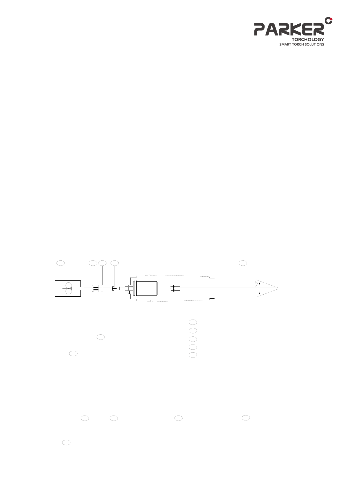
Front-end consumables
The nozzle, contact tip and diffuser all run at very high
temperatures and you should regularly inspect them
for wear and operational damage. When changing a
contact tip, always use a contact tip spanner to prevent
over tightening. Repeated over tightening will destroy the
threads in the tip adaptor.
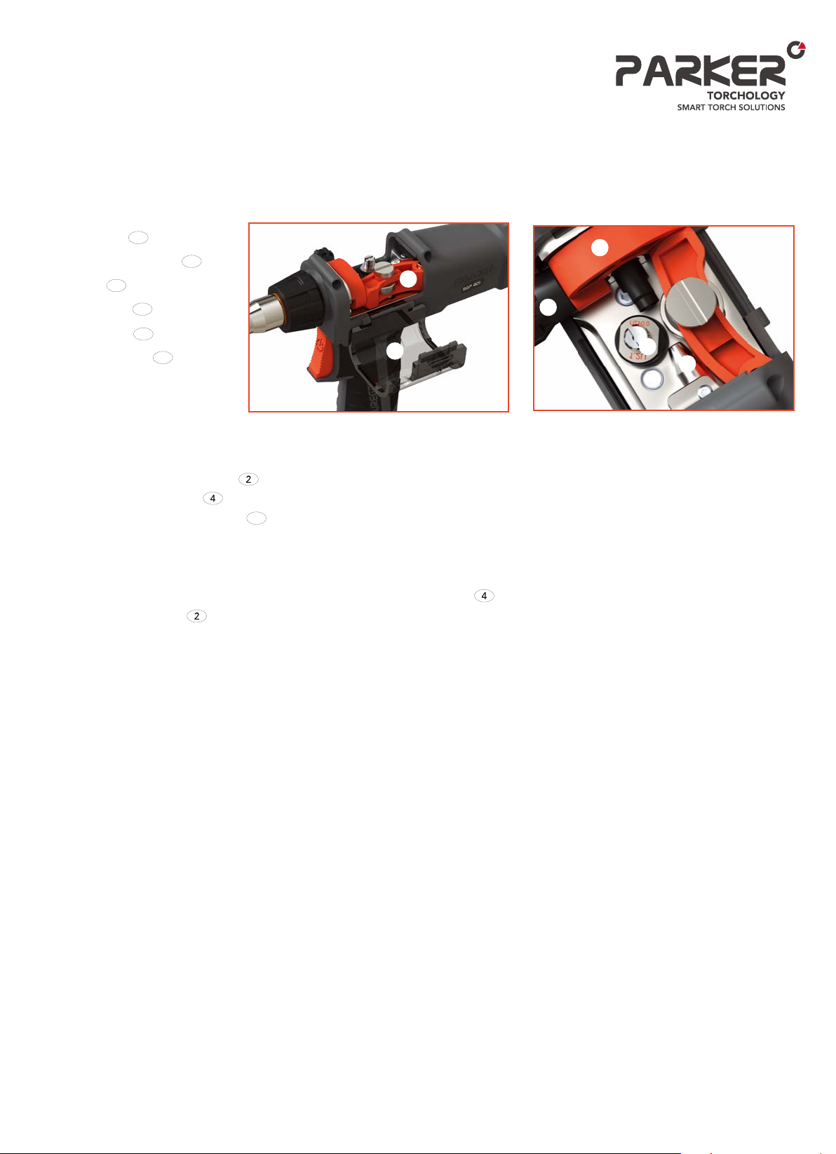
Drive Rolls
Always make sure you have the correct drive roll for the
type and size wire you are using and note that the drive
roll threads are Left-Hand and the drive roll can be
inverted to double its life.
The drive roll and pressure roll should be inspected
regularly for wear. Run the gun in a quiet place, without
wire feeding and listen for any unusual noises. You can
eliminate pressure roll from drive roll noise by releasing
the pressure arm. If you suspect something is wrong,
you should contact your distributor or dealer.
The area around the drive roll should be regularly
dusted off to prevent dust and workshop debris from
accumulating. We do not recommend lubricating the
drive shaft or pressure roll. These are sealed for life
units and lubrication oils or greases will only pick up dust
and turn these oils and greases into a grinding paste. A
simple dust off is all that is required.
The gearbox, drive motor and shaft top bearing are also
sealed for life. No maintenance is required.
Parker Torchology Pull-Mig Warranty
Every Parker Torchology Pull-Mig welding torch is
manufactured to the highest standards and carries a 3
month warranty from the date of sale to the end user. The warranty
covers and is limited to, a fault developing as a result of faulty
workmanship or faulty
materials.
What is covered?
• Defective materials used in the manufacture of the product.
• Faulty workmanship in the manufacture of the product
What is not covered?
• Incorrect use or damage.
• Normal wear and tear to either the product or the
consumables supplied with the product.
• Faults arising from using non-Parker Torchology
spare parts.
• Direct or indirect costs of any form arising as a result of
a suspected, or actual, defective product.
How to make a claim.
This warranty is limited to the original purchaser of the product, it
is not transferable. If a fault is suspected, the dealer or ourselves
must be contacted and informed of the fault before the product is
returned.
You can contact us by
Mail: sales@parkertorchology.com
How will we handle any claim?
Parker Torchology's sales office may ask you to return the product
with a copy of your proof of purchase, (If you are the end-user) or a
copy of proof of sale (If you are a distributor).
Depending on the nature of the claim, we may ask one of our
technical staff to discuss the problem with you to get a quick
resolution.
Once the cause of the problem is established and at our
discretion, we will either repair or replace the defective product
free of charge.
We will refund the costs incurred in returning the product if a
defect is found, but will only refund normal transport costs. We
will not pay for UPS, Express deliveries or any other high speed
carriers.
If we believe the product failure is as a result of any reason other
than defective materials or manufacture, we will issue a written
report to you detailing our findings.
Other issues.
Whilst Pull-Mig welding torches will give long and lasting
service, we do understand the harsh and demanding working
environment in which our products operate, therefore Parker
retain the right to deal with any fault in a manner that best suits
Parker Torchology.
This warranty is an addition to Parker’s standard terms and
conditions and Parker's standard Terms and Conditions of Sale
will take precedence over this warranty.
Maintenance, Fault Finding, and Warranty.
8


Form ref: MN_PARKER_PULL_001
Floor 1 & 2, No.358, Gang Xing Er Road
Jinan Area of China (Shandong) Pilot Free Trade Zone
Jinan 250102 P.R. China
Tel: +86 531 88239823
Fax: +86 531 88239398
Website: www.parkertorchology.com
Email: info@parkertorchology.com
MPP010 / V.2021.01
This manual suits for next models
1
Table of contents
Popular Welding Accessories manuals by other brands

Milweld
Milweld Auto Arc XLT 165, XLT 135 owner's manual

Sealey
Sealey Siegen Tools S01000.V2 Instructions for use

LAHTI PRO
LAHTI PRO L1540600 instruction manual

Miller Electric
Miller Electric Gyro Bail-15/25 owner's manual

Abicor Binzel
Abicor Binzel xFUME PRO Original operating instructions

Sthor
Sthor 74483 manual