Thank you for purchasing this quality product. To ensure correct function and safety, please read and save all
instructions before using the product
THANK YOU FOR YOUR PURCHASE
CAUTION
READ INSTRUCTIONS CAREFULLY FOR SAFE
INSTALLATION AND FAN OPERATION. IF UNSURE CONSULT
A QUALIFIED ELECTRICIAN
F6262110V
Installation & Operating Instructions for the
Parrotuncle Owner’s Installation ,Manual
WARNING: SHUT POWER OFF AT FUSE OR CIRCUIT BREAKER
Parrotuncle Lighting, 218 Black Tie Lane, Chapel Hill, NC www.parrotuncle.com
Parrot Uncle YOU CAN BE SURE OF are trademarks of Eileen Grays LLC. Used under license by Eileen Grays LLC. Made in CHINA
All rights reserved.
This fan is designed for indoor use.
OWNER'S MANUAL
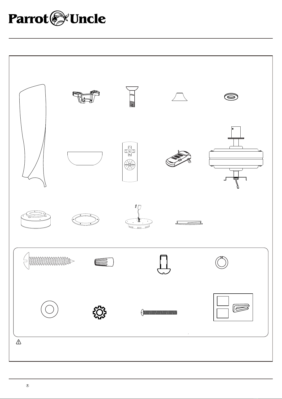
Content: 1 Piece
Read the instructions before installing the ceiling fan.
Keep this manual for future reference.
FEATURES
Distance to floor
2.3m (7.5 ft)
Distance from the wall
30 cm (1 ft)
CAUTION!
To reduce the risk of injury to personst,he fan must be installed so that the blades are at a
height greater than 2.3 meters (7.5 feet) above the floor.
WARNING / CAUTION
Please observe the following general safety precautions carefully before and during all phases of handling, installation, removal, operation and maintenance of this product. Failure to comply with
these precautions violates safety standards of design, manufacture and intended use of the product. Mercator assumes no liability for customer’s failure to comply with these requirements.
A WARNING / CAUTION notice denotes a hazard. It calls attention to an installation procedure,
operating procedure, maintenance procedure, or the like, that if not correctly performed or
adhered to, could result in damage to this appliance, personal injury or death. Do not proceed
beyond a WARNING / CAUTION notice until the indicated conditions are fully understood and
met.
SAFETY SYMBOLS
Alternating current
Protective earth
Warning/Caution
1. Read all instructions and safety information. Review assembly diagrams provided before installing your new ceiling fan.
2. This fan must be installed by a licensed and qualified electrician according to ETL and local authority regulations.
3. This appliance is not intended for use by persons (including children) with reduced physical, sensory or mental capabilities, or lack of experience and knowledge, unless they have been given
supervision or instruction concerning use of the appliance by a person responsible for their safety.
4. Young children should be supervised to ensure that they do not play with the appliance.
5. All electrical works must only be undertaken after disconnection of the power by removing fuses or turning off the circuit breaker, to ensure all pole isolation of the electrical supply.
6. Do not use outdoors where it could be exposed to water or moisture.
7. This manual is not intended to instruct or assist untrained or unqualified persons to install this ceiling fan.
8. It is the responsibility of qualified, licensed installer and user to apply common sense and care at all times during installation and operation.
2. For fan installed enclosed outdoors, the fan must be installed at least 1.5m from the perimeter of roof/eaves of the enclosure to protect the product from direct or indirect rain water or sunlight.
3. The chosen location for the fan must not allow the rotating blades to come into contact with any object.
4. Please check carefully and make sure that ceiling joists are strong enough and of adequate size to support the weight of about 35 kg.
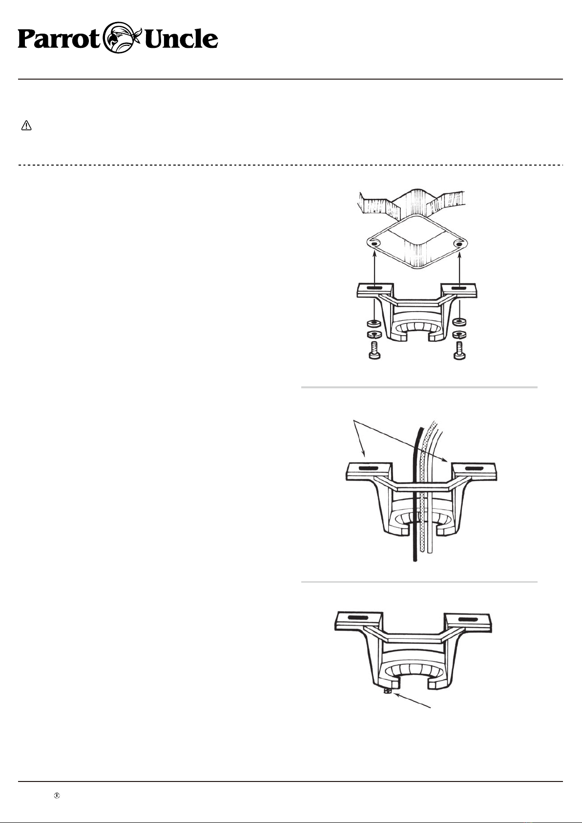
5. To reduce the risk of fire, electrical shock or personal injury, please make sure that the fan mounting bracket is directly supported from the building structure. Do not mount to an outlet box.
6. The mounting bracket must be firmly screwed to a load bearing building structure e.g. a concrete ceiling, steel structure, or a timber frame. If additional timber frames are to be added, those
must be securely nailed or screwed between the beams.
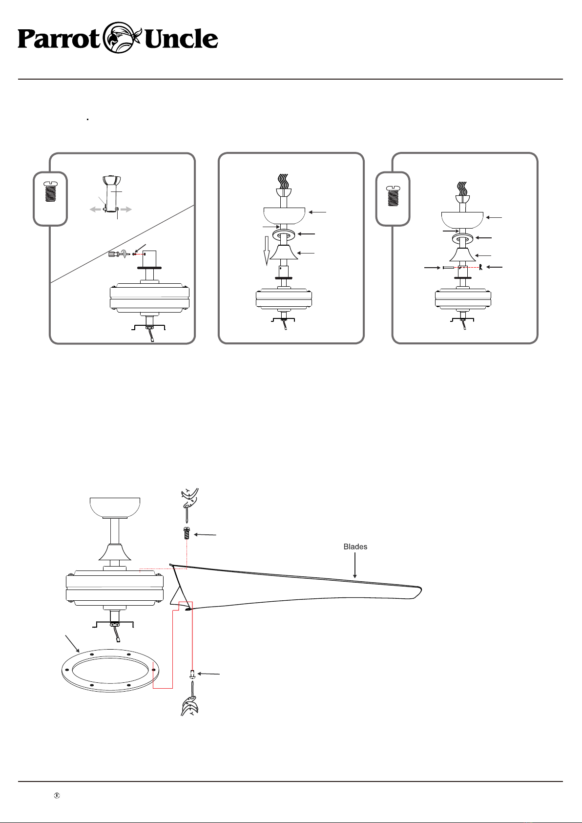
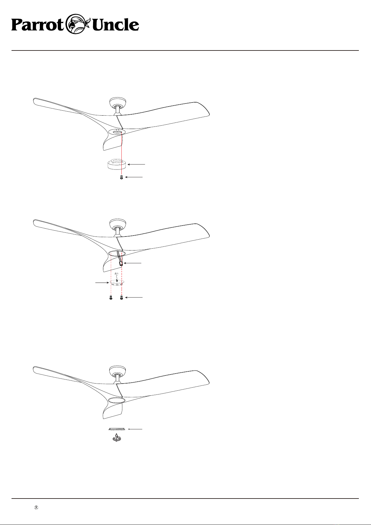
7. Attach fan blades after the fan motor housing is installed and properly secured. Keep the fan motor and blades in the original package until it is ready to be installed.
SAFETY PRECAUTIONS
8. Check and confirm, after the fan is completely installed, that all connections are proper and secure to prevent the fan from falling or causing property damages or personal injury.
9. Take care not to bend or damage the motor Drive Shaft or Fan Blades when handling or installing them. If such defect is noticed, please contact the Customer Service before installation of the
ceiling fan.
10. Fan and hanging (mounting) bracket must be earthed.
11. Use of an unapproved remote controller voids the warranty. Only Mercator remote controllers are approved for use with Mercator ceiling fans. Do not use solid state controllers.
12. Do not remove the fan from the ceiling after installation.
13. Make sure electricity is turned off at the main power box before commencing work. Turn off the power by removing fuse or turning off circuit breaker before installing the fan and replacing
HOW TO CHOOSE A PROPER LOCATION FOR CEILING FAN
lamps.
1. According to regulations and to provide a safe clearance from the floor, the lowest point on the fan blade must be at least 2.1 metres (7 feet) from the floor.
SAFETY WARNINGSSAFETY WARNINGS
SAFETY PRECAUTIONS