INSTRUCTION REF: IN104
ISSUE No. 2
DATE 10.04.06
Page 3 of 15
TELEPHONE: SERVICE (44) 01332 875665
FAX: SERVICE (44) 01332 875536
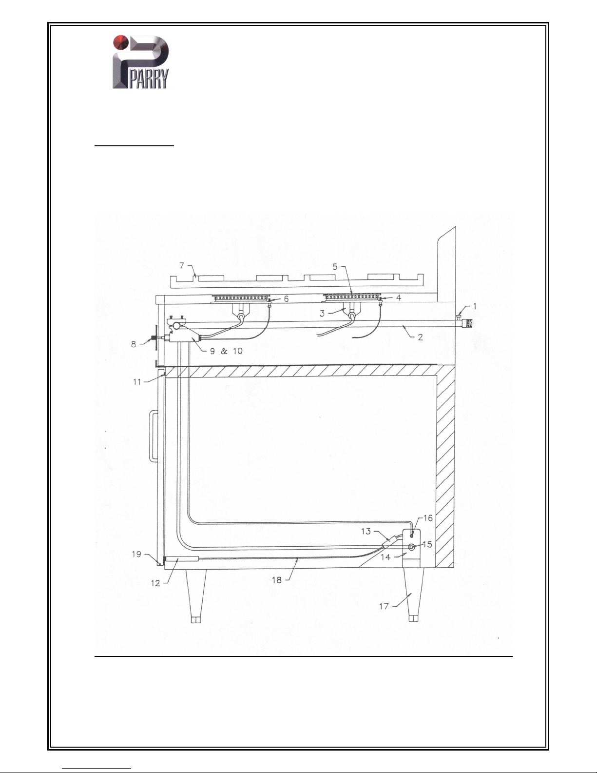
GAS CONNECTION
The size of the supply pipe should be no less than ½”B.S.P. and an easily accessible isolation
tap fitted close to the appliance in the gas line. Although a rigid connection is recommended. A
Gas Council approved armoured flexible pipe may be used in conjunction with a straining cable.
INSTALLATION
Before the appliance is commissioned the gas safety regulations require that all connections on the gas
line are tested for gas soundness between the gas meter and the appliance.
All packing and protective film must be removed from panels etc. prior to commissioning the appliance.
All gas appliances must be fitted by a competent person to gas safety regulations 1984.
For fitting instructions see installation section.
All burners are fitted with flame failure device, spar ignition is not provided to hob burners only to oven
burners.
(a) To light Hob Unit turn knob to
position.
(b) Press in and ignite gas with a match, keep knob held in for 15-20 seconds.
(c) Release knob, gas should stay lit. If gas goes out repeat (b).
(d) The burner is now on full gas, to turn gas down turn knob in an anti-clockwise, this is the lowest
setting, which is factory set.
(e) To turn burners off, turn knob clockwise all the way round.
(f) We advise these appliances should not be left unattended while switched on.
(g) These appliances are for professional use by qualified people only.
(h) There are no user serviceable parts.
(i) A drip tray is fitted beneath the hob burners to catch any spillage, during normal use, this tray may get
hot. Only remove when tray has cooled or with suitable gloves.
OVEN
To light oven, open doors, turn oven knob to approximate gas mark 5 press and hold silver knob on oven
base panel press the piezo ignitor button on bottom of the oven.
After pressing button 2-3 times burner should light. Keep oven knob depressed for 15-20 seconds. Flame
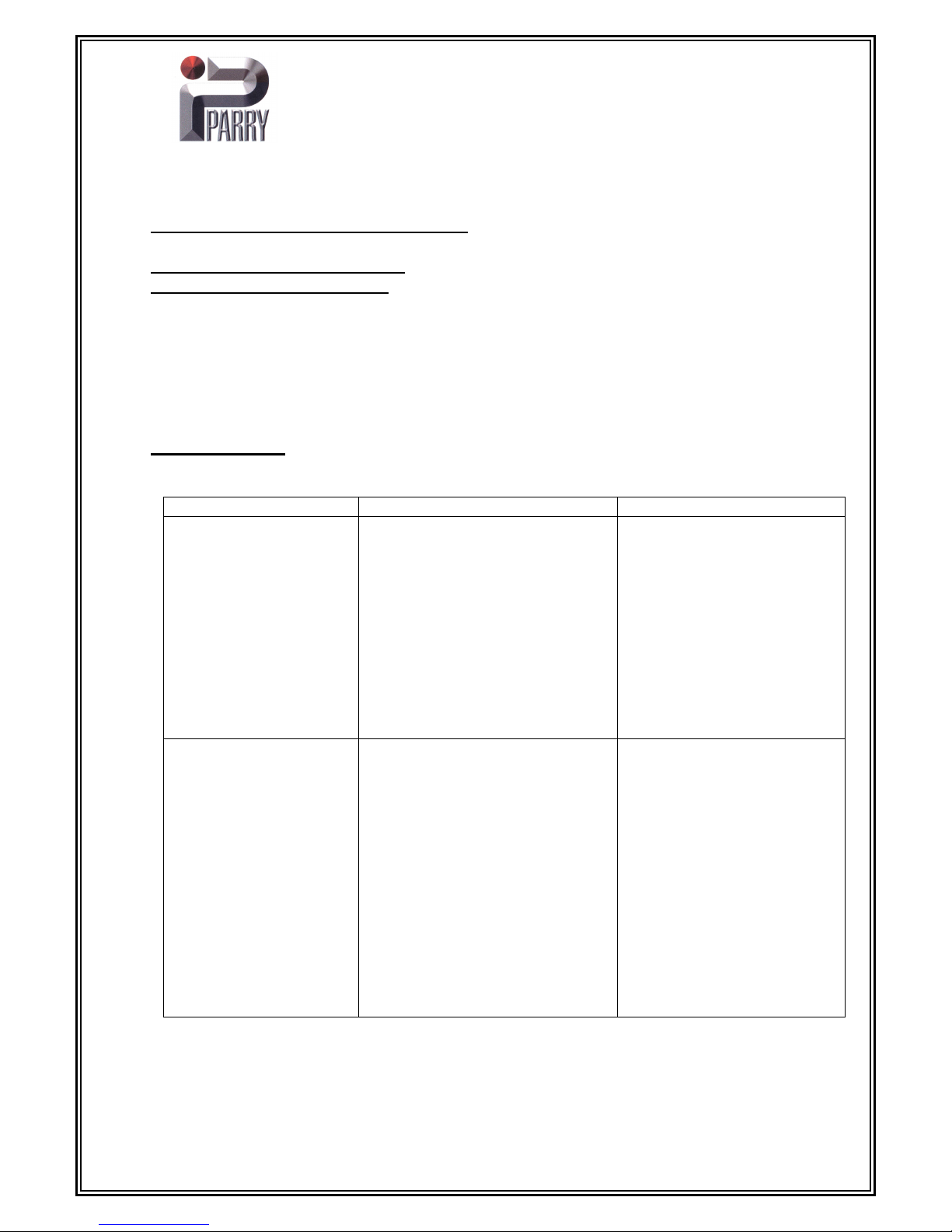
should remain lit, if not repeat above sequence. If burner goes out refer to fault finding chart. When burner
stays on oven is ready for use, repeat for other side. select gas mark required, turn knob to setting, oven
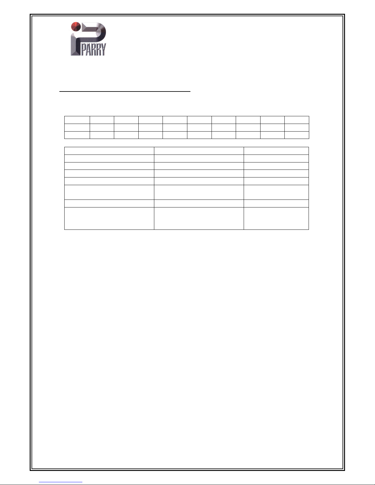
flame will decrease when desired temperature is reached. There are three shelf positions in the oven, the
following guide is only intended as a guide to temperature in the centre of the oven. It is strongly
recommended that the user makes note of best results, temperatures can vary as much as 20˚c hotter at
top of oven and 30˚c cooler at the bottom of the oven.