Parweld XR1052 User manual

XR1052 (XR950H) / XR939H
Schweiß- und Schleifhelm mit automatischem Klapp-
Schweißerschutzfi lter ● Lichtreaktiv ● Benutzerhandbuch
S
S
S
S
S
DE
Casco de soldadura y amolado de auto-oscurecimiento con fi ltro
abatible ● Reactivo a la luz ● Manual de instrucciones
C
C
C
a
ES
Casco per saldatura e molatura con fi ltro fl ip-up auto-oscurante
● Sensibile alla luce ● Manuale utente
C
C
●
●
IT
Asque de soudage & meulage à cartouche antiéblouissante
rabattable ● Sensible à la lumière ● Instructions d’utilisation
FR
Auto Darkening Flip Filter Welding & Grinding Helmet
● Light Reactive ● User Manual
A
A
●
EN

2
XR1052 / XR939H

3
XR1052 / XR939H
English ................................................................................................................... page 4
Français ............................................................................................................... page 16
Deutch .................................................................................................................. seite 28
Espagnol........................................................................................................... página 40
Italiano .............................................................................................................. pagina 52
EN
FR
ES
IT
DE

4
XR1052 / XR939H
Fumes and Gases
Fumes and gases emitted during welding may be dangerous, use
adequate ventilation and extraction equipment.
WARNING
Safety
Safety
Read Instructions
Before using this product, read the instructions and any related data
sheets. (See www.parweld.com).
Injury can occur from bodily contact with hot parts, sparks, fumes, dust,
noise and vibration.
Protect your eyes and face with a mask fi tted with a fi lter lens. Use
welding screens.
Wear protective clothing to protect your body and ears.
Use adequate ventilation or wear respirator equipment to prevent dust,
fumes and gases from entering your lungs.
Electric Shock
Electric shocks can kill, use adequate protective equipment. Ensure a
safe earth connection. Do not touch electrical parts or electrode.
Arc Rays
Arc rays may burn eyes and skin. Wear protective clothing.
Burn and Fire Hazard
Weld and metal parts are hot and cause serious burn injuries if
touched. Sparks can cause burns and fi re. Remove all fl ammable
materials from the welding area.
| English
EN English

5
XR1052 / XR939H
Key Features
The helmet has a recessed front for the auto darkening fi lter (ADF) unit covered
by a front visor lens that provides high impact protection suitable for grinding (1B
Impact rated). Both the internal ADF cover lens and front visor lens are easily
changed.
The ADF has a fl ip-up action when a fully clear view is needed.
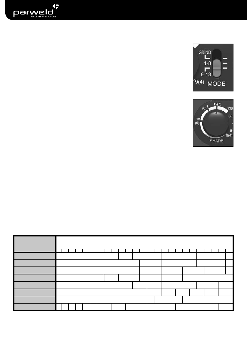
The ADF gives true colour view, light shade of 3 - 3.5 suitable for grinding and has
a full shade level range variable from 4 -13. The sensitivity is adjustable, as is the
delay function. All modes are switchable on the outer control with adjustment dials.
The auto darkening switch function uses four optical sensors mounted in an array
for multi direction and complete space sensing.
The 13 in 1 optical coating provides extremely high UV/IR protection level.
The ADF optics are solar cell powered which has a replaceable lithium backup
battery. A test button feature enables a battery voltage check with an LED light
indicating if low. This button also enables an ADF shading test to check it is function
correctly.
The helmet shell is manufactured from lightweight impact resistant material fi nished
in a mark resistant gloss coating that also resist weld spatter & sparks.
The head gear has multiple rake positions and adjustment for a precise fi t with
comfortable sweatband padding and designed with a special up / down mechanism.
When raised over the head, the headband mechanism positions the center of
gravity low and aligned with the center of welder’s head. This greatly lowers neck
fatigue and make the welder feel more comfortable while working.
At the top of the XR1052 / XR939H helmet shell is fi tted with an air blower system
standard female port for a male hose. Around the helmet perimeter is a head
and neck seal to keep weld fumes out of the helmets internal, breathed clean air,
environment.
The key helmet components fully conform to all relevant international safety
standards, and have excellent full-face, head & neck protection and suitable for
TIG, MIG/MAG, MMA, grinding and plasma processes.
English |

6
XR1052 / XR939H
Technical Data
Technical Data
Viewing Area: 100mm × 65mm / 3.94” × 2.56”
UV/IR Protection: Up To Shade DIN 16 all the time
Selectable Mode: Welding Shade Range / Grinding
Light State Shade: 3 -to- 3.5
Variable Shade: 4 -to- 8 / 9 -to-13
Depending on mode selected and shade control
adjustment.
Filter CE Optical Class: 1/1/1/1
Reaction Time: 0.000033 sec ( 1/30,000 s)
Shade Clearing Delay
Time:
0.3s -to- 0.9s
Depending on sensitivity control adjustment.
Optical Sensors: Four infrared detectors
Power Supply: Solar cells + Lithium battery
(Replaceable battery: CR2450 x1)
Power On/Off : Fully Automatic
Operating Temperature: - 5°C to + 55°C ( 23°F to 131°F )
Storing Temperature: - 20°C ~ + 70°C (-4 ° F to 158° F)
Helmet Material: High-impact resistant Polyamide (Nylon)
Helmet Class: EN 175 F CE
Total Weight: 540 g
Conforms with Standards: EN 379 : 2003 + A1 : 2009
EN 175 : 1997
EN 166 : 2001
| English

7
XR1052 / XR939H
Initial Setup
Please read thoroughly and understand this user manual to ensure correct, safe
and eff ective use of the helmet. Failure to do so can result in serious injury.
Also keep the manual safely for future reference.
The helmet comes ready for use, but before welding;
• Check the front visor and cover lenses, remove the protective fi lm and make
sure that they are clean, and free of dirt and are retained securely.
• Check the four optical sensors on the front of the fi lter cartridge are not
obstructed.
• Adjust headband so that the helmet is seated as low as possible on the head
and close to your face. Adjust helmet’s angle when in the lowered position
by slackening the retaining nuts and repositioning the rake limitation plates.
Also adjust the fi t of the headband using the rear ratchet nut. Detail headband
adjustment instructions follow in this user manual.
• Set the mode switch to Grind or one of the Shade ranges and adjust the shade
to the shade number required depending of the work application. Detail setting
instructions follow in this user manual.
• Set the helmet in the lowered position correctly before welding.
• Check for light tightness before each use, making sure there are no gaps
between the ADF and the shell around the edge.
After welding inspect all operating parts for signs of wear, scratches, cracks, pitting
and if any parts are damaged they should be replaced immediately before using
again to avoid serious personal injury.
Warning: When welding or grinding the helmet will not protect other body parts,
please wear other safety equipment that provides suitable protection.
English |

8
XR1052 / XR939H
Mode Switch
When grinding, Select GRIND on the MODE switch.
When welding, select one off two positions on the MODE switch
corresponding to the shade range required; Shade 4 through to 8
or shade 9 through to 13.
Shade Control
When the mode switch is in the lower position, 9 - 13, the SHADE
control knob adjustment most be set to correspond with the shade
required on the scale between 9, 10, 11 12 and 13.
When the switch is in the mid position. 4 - 8, the SHADE control
knob adjustment most be set to correspond with the shade
required on the scale between 4, 5, 6, 7 and 8.
Choose the correct shade number based on welding amperage and process.
If the shade of fi lter is too dark or too light, adjust the SHADE control knob slightly
until you can see the welding spot and molten weld pool without glare, or excessive
brightness.
Warning: You can damage your eyes if using the welding helmet with incorrect
shade selected (Too light or too dark) for long periods of time.
Controls
Recommended Shade Numbers
WELDING PROCESS
CURRENT AMPERES
0.5 1 2.5 5 10 15 20 30 40 60 80 100 125 150 175 200 225 250 275 300 350 400 450 500
Covered Electrodes Shade 9 10 Shade 11 Shade 12 Shade 13 14
MIG Plate Welding Shade 10 Shade 11 Shade 12 Shade 13 14
MIG Sheet Welding Shade 10 Shade 11 Shade 12 Shade 13 Shade 14 15
TIG Shade 9 10 Shade 11 Shade 12 Shade 13 Shade 14
MAG Shade 10 11 12 Shade 13 Shade 14 15
Arc Gouging Shade 10 11 12 13 14 15
Plasma Cutting Shade 11 Shade 12 Shade 13
Plasma Welding 4 5 6 7 8 9 10 11 Shade 12 Shade 13 Shade 14 15
| English

9
XR1052 / XR939H
Delay Switch
The DELAY switch aff ects the time taken to switch the fi lter from
dark state to light state.
Switch in the lower position, the delay time is short; 0.3s-0.5s
Switch in the Upper position; the delay time is long; 0.6s-0.9s
The switching time may vary due to diff erent welding types and
diff erent sensitivity setting even when the delay switch is at the same position.
If the fi lter is fl ickers between dark and light states under low current welding,
increase the delay time, this can correct this issue.
Warning: Avoid damage to the eyes from the residual arc or welding molten pool
glare exposure, becuase too fast a switching time to light state, when welding stops
(Break arc).
Controls
Sensitivity Control
Before welding, always adjust the sensitivity to the high position.
If encountering interference of external lighting sources such work
lighting this may cause the fi lter to darken continuously and fail
to lighten when not welding. If this occurs, adjust the sensitivity
control towards the low position slightly, until the fi lter returns to
the light state. Don’t position the helmet towards a light source
during this process, it should be towards the welding position or workpiece.
During welding, the sensitivity control should be adjusted as high as possible, or it
will aff ect the darkening speed of the fi lter.
Warning: If the fi lter does not darken or the darkening shade is not enough or
the darkening speed is too slow or the fi lter is fl ickering, it is not working correctly.
Check the mode and shade settings are correct for welding amperage and process
and conditions. If you cannot identify the reason for the faulty operation, you must
stop using the helmet immediately and contact the suppler.
English |

10
XR1052 / XR939H
Test Button
The test button on the ADF battery housing is used to
check if the lithium battery has power and also if the
fi lter working correctly.
When the test button is pressed, the battery indicator
LED will light (Red) and the ADF shade dark briefl y.
This means the fi lter is working correctly.
If the battery indicator does not light or the light is very
weak, the lithium battery must be replaced.
If the battery indicator is lit but the fi lter does not
darkening briefl y, it means there is some problem with
the fi lter, don’t use the until the ADF has been replaced.
Battery
Replacing ADF Battery
2. The battery should be visible and sitting
loosely in the housing.
3. Carefully remove the
battery by tipping it out.
4. Fit new CR2450 battery. Pressing in, with
minimal force, until face is fl ush with hosuing.
5. Fit cover. Press and rotate clockwise until arrows on the
cover and ADF housing align.
1. Twist the cell cover counter clockwise to remove it.
| English
OFF
ON

11
XR1052 / XR939H
Adjusting The Head Band
To fi t and adjust the welding helmet position on your head, fi rst place helmet over
your head.
Adjust the tightness of the headband, use the rear nut (1). Adjust until it is a good fi t
around your head.
Adjust the height at which the helmet sits on top of your head, adjusting the top
strap (2), by pressing the strap apart repositioning the clip in a new strap hole and
pressing together again.
Adjust the nose to fi lter distance on both sides of the head band, unclip the side
bracket (3), slide the head band backwards or forwards into a suitable position for
your head, then press the clips back into place to secure.
Adjust the rake angle so that the viewing window is in front of your eyes and the
base of the helmet sits close to the chest in the down position. Slacken the external
nuts on the helmet sides (4) and then move the slotted rake angle plates (5) on the
inside of the helmet. Locate the plates onto the shell tabs in the new position to set
the rake angle.
Wearing Position
English |
(1)
(2)
(
(
(
(2
(2
(2
(2
(2
(3)
(3)
(4)
(5)
(5)
(5)
(4)
(4)
(4
(4
(4
(4
(4
(
(

12
XR1052 / XR939H
The helmet has three modes of operation.
Mode 1 - Welding mode.
Either shade range selected giving the full range of shades with adjustment of the
shading number from shade 4 to 13. This is the normal state, with high-defi nition,
true colour display while welding and light shading of shade 3 & 3.5 while not
welding.
Mode 2 - Grinding mode (Electronically Switched).
GRIND mode selected, this is the grind state with high-defi nition and true colour
display with light shading of shade 3 & 3.5 only.
Mode 3 - Grinding mode (ADF fl ipped up inside helmet, open view).
The ADF is mechanically fl ipped up inside the helmet using the two side of helmet
levers. The welder’s view is unobstructed but protected by the front fully transparent
visor.
This mode is especially suitable for Powered Air Purifying Respirator (PAPR)
equipment when the welder is wearing the helmet in a contaminated environment.
Also if the welder needs to do operations in dark ambient light or needs a large
window to view the workpiece.
Note: The auto-darkening fi lter has all the function necessary for the welding and
grinding applications and off ers the best protection from serious personal injury.
Each mode is independent and all functions cannot be applied at the same time.
The fl ipped up fi lter function should only be used when the other modes do not
enable a satisfactory view of the workpiece in low risk of injury conditions.
Modes of Operation
Note:The levers should be operated up / downward at the same time both hands.
| English

13
XR1052 / XR939H
Item Description Stock Code
Auto Darkening Flip Filter Welding & Grinding Helmet
c/w Head Band, Face Seal and Duct
XR1052
(XR950H) ●
Auto Darkening Flip Filter Welding & Grinding Helmet
c/w Head Band ● XR939H
1 Auto Darkening Filter Cartridge c/w Control XR9560
2 Front Cover Visor XR9520
3 Inside Cover Lens (106mm x 70mm) XR9530
4 Headband Sweat Pads (Front, Top and Back) XR9550
5 Headband Assembly XR9540
6 Face Seal XR9570 ●
Lithium Battery CR2450
Spares
English |
12
3
4
5
6

14
XR1052 / XR939H
Replacing the Front Cover Visor
To remove the front cover visor pull on the side tab that is hooked onto the helmet
shell. It should click off and slide out of the top and bottom retaining lips. The
opposite side should detach easily.
Remove the protection fi lm from both sides of the new visor. Place the one end of
the visor into the side retaining lips and over the hook. On the opposite side align
the tab over the hook. First press the top and bottom corners into the edge retaining
lips then press the tab until it click into the hook of the helmet shell.
Replacing the Inside Cover Lens
Lift up the middle of the lower edge of the lens fi tted to the ADF unit, it should bow
and slide out of fi lter retaining side clamps.
Remove the protection fi lm from both sides of the new Lens. Place the new lens
onto the back of the ADF slide the one side under the side clamp. Flex the lens so
that it bows and push the opposite edge under the other side clamp then release it.
Clean the lens and visor with a lint-free tissue or cotton cloth. Do not immerse the
lens or visor in water or any other liquid. Do not use abrasives, solvents or oil based
cleaners.
Replace the Front Lens Cover if it is cracked, scratched or damaged in any way.
Regularly check if the battery needs replacing by pressing the test button.
Clean fi lter’s surfaces regularly. Protect fi lter from contact with any liquid and dirt.
Do not immerse the fi lter in water.
The auto darkening fi lter must never be exposed to or placed on a hot surface.
Do not remove the auto-darkening fi lter from the welding helmet. Do not try to open
the fi lter.
The manufacturer provides a warranty of 24 months from invoice date for all
manufacturing defects. The warranty becomes void if not operated according to the
instruction manual. The warranty becomes void if the helmet has been modifi ed in
any way.
Maintenance
Warranty
Declarations
Declarations
For all declarations of conformity to CE, RoHS and WEEE compliance, please refer
to the Parweld website at www.parweld.com.
| English

15
XR1052 / XR939H
Trouble Shooting
Trouble Shooting
Problem Remedy
Filter shade is too dark can not see
weld pool
Check the correct shade range is
selected.
Adjust the shade control until you
can see the welding spot and molten
weld pool without glare, or excessive
brightness.
Filter shade is too light excessive
brightness from the weld pool
Check the correct shade range is
selected.
Adjust the shade control until you
can see the welding spot and molten
weld pool without glare, or excessive
brightness.
Filter shade darkened continuously and
fails to lighten when not welding
Adjust the sensitivity control towards
the low position slightly until the fi lter
returns to the light state. Do this while
looking at the workpiece to limit external
light source interference. Try to keep
sensitivity adjusted as high as possible
to maintain fastest shading reaction
speed.
Filter is fl ickers between dark and light
states under low current welding.
Increase the delay time.
Warning:Too fast a switching time to
light state will lead to serious eye injury.
Filter does not darken or does not
darken enough.
Check all settings mode, shade,
sensitivity and delay.
Check the battery by pressing the test
button. Replace is necessary.
Warning: If all checks and adjustments
do not correct the problem you must
stop using the helmet immediately and
contact the supplier or a technician.
Filter darkening speed is too slow.
Filter fl ickers from darkened shade to
light shade.
Battery indicator does not light or the
light is very weak when the test button
is pressed
The lithium battery is weak and must be
replaced. (CR2450).
Battery indicator is lit but the fi lter does
not darken briefl y.
There is some problem with the fi lter,
don’t use until it has been replaced.
English |

16
XR1052 / XR939H
FR Français
Fumées et gaz
Les fumées et les gaz générés lors du soudage peuvent être dangereux,
utiliser un équipement ad hoc de ventilation et d’extraction.
AVERTISSEMENT
Sécurité
Sécurité
Lire les instructions d'utilisation
Avant d’utiliser ce produit, lire les instructions d'utilisation ainsi que les
fi ches techniques aff érentes. (voir www.parweld.com).
Utiliser un équipement de ventilation adéquat ou porter un équipement
de protection respiratoire pour éviter d'inhaler des poussières, des
fumées et des gaz.
Choc électrique
Les chocs électriques peuvent être mortels, utiliser un équipement de
protection adéquat. Veiller à la mise à la terre correcte. Ne pas toucher
les composants électriques ni l’électrode.
Rayons de l’arc
Les rayons de l’arc peuvent provoquer des lésions oculaires et des
brûlures cutanées. Porter des vêtements de protection.
Risque de brûlures et d’incendie
La soudure et les pièces métalliques sont brûlantes et peuvent
causer de graves brûlures en cas de contact. Les étincelles peuvent
causer des brûlures et un incendie. Enlever toutes les substances
infl ammables hors de la zone de soudage.
Risque de blessures en cas de contact avec des pièces brûlantes, des
étincelles, des fumées, des poussières, ainsi qu’en cas d’exposition au
bruit et aux vibrations.
Protéger les yeux et le visage avec un masque doté d’un écran fi ltrante.
Utiliser des écrans de soudure.
Portez des équipements de protection pour protéger votre corps et vos
oreilles.
| Français

17
XR1052 / XR939H
Caractéristiques-clés
Le casque présente une face avant en retrait pour la cartouche antiéblouissante
(ADF) laquelle est recouverte par une visière frontale qui off re une protection élevée
contre les impacts dus au meulage (impact nominal 1B). L’écran de protection
intérieure ADF et la visière frontale peuvent être remplacées en toute simplicité.
L’ADF peut être rabattue lorsqu’il faut disposer d’une vision parfaitement claire.
L’ADF donne une vue en couleur réelle avec une teinte de 3 - 3,5 compatible pour le
meulage et possède une gamme complète de niveaux de teinte variable de 4 -13. La
sensibilité et la fonction de temporisation sont réglables. Tous les modes peuvent être
commutés sur la commande externe via les touches de réglage.
La fonction d’obscurcissement automatique utilise quatre capteurs optiques disposés
en réseau pour une détection multidirectionnelle et complète de l'espace.
Le revêtement optique 13-en-1 garantit un niveau de protection UV/IR extrêmement
élevé.
Les optiques ADF sont alimentées par une cellule solaire avec pile de secours au
lithium remplaçable. Un bouton de test permet de vérifi er la tension de la pile avec
une LED indiquant une charge faible. Ce bouton permet également de tester le
fonctionnement correct de l’obscurcissement ADF.
La coque du casque est fabriquée à partir d’un matériau léger et résistant aux chocs,
avec un revêtement de fi nition brillant anti-marques résistant aux projections &
étincelles de soudage.
Le harnais de tête présente plusieurs positions d’inclinaison et de réglage pour un
ajustement précis, avec un rembourrage confortable à bandeaux anti-sudation et un
mécanisme spécial haut / bas. Relevé au-dessus de la tête, le mécanisme du harnais
positionne le centre de gravité plus bas, aligné sur le centre de la tête du soudeur.
Ceci réduit considérablement la contrainte exercée sur le cou du soudeur qui peut
ainsi travailler plus confortablement.
La partie supérieure de la coque du casque XR1052 / XR939H est dotée d’un
système de ventilation avec port femelle standard pour l’embout de tuyau mâle. Un
joint spécial pour la tête et le cou est aménagé autour du casque afi n d’exclure toute
infi ltration des fumées de soudage dans l’air frais respirable à l’intérieur du casque.
Les principaux composants du casque sont pleinement conformes aux normes
internationales de sécurité et garantissent la protection intégrale de la tête & du cou ;
ils sont compatibles avec les procédés TIG, MIG/MAG, MMA, de meulage et au
plasma.
Français |

18
XR1052 / XR939H
Caractéristiques techniques
Champ de vision : 100 mm × 65 mm / 3,94” × 2,56”
Protection UV/IR : Permanente jusqu’à la teinte DIN 16
Sélection de mode : Plage de teinte pour soudage / meulage
Teinte claire : 3 à 3,5
Teinte variable : 4 à 8 / 9 à 13
selon le mode sélectionné et le réglage de la teinte.
Classe de fi ltre optique CE : 1/1/1/1
Temps de réaction : 0,000033 sec (1/30.000 s)
Temporisation
d’éclaircissement de teinte :
0,3 s à 0,9 s
selon le réglage de la sensibilité.
Capteurs optiques : Quatre capteurs infrarouges
Alimentation électrique : Cellules solaires + pile au lithium
(pile remplaçable : CR2450 x1)
Mise sous/hors tension : Totalement automatique
Température de service : - 5°C à + 55°C (23°F à 131°F)
Température de stockage : - 20°C à + 70°C (4°F à 158°F)
Matériau du casque : Polyamide (nylon) à haute résistance aux impacts
Classe de casque : EN 175 F CE
Poids total : 540 g
Conformité aux normes : EN 379 : 2003 + A1 : 2009
EN 175 : 1997
EN 166 : 2001
| Français

19
XR1052 / XR939H
Configuration initiale
Veiller à lire attentivement et bien comprendre les présentes instructions d’utilisation
pour garantir l’utilisation correcte, sûre et effi cace du casque. Le non-respect peut
entraîner de graves blessures.
Conserver les instructions en un lieu sûr afi n de pouvoir les consulter.
Le casque est livré prêt à l’usage mais veiller aux points suivants avant d’entamer
le soudage :
• Vérifi er la visière frontale et les écrans de protection, enlever le fi lm protecteur et
veiller à ce que ces composants soient propres et fermement en place.
• Vérifi er si les quatre capteurs optiques à l’avant de la cartouche de fi ltre ne sont
pas obstrués.
• Ajuster le harnais de tête de manière que le casque repose aussi bas que
possible sur la tête et soit proche du visage. Ajuster l’inclinaison du casque en
position abaissée en desserrant les écrous de retenue et repositionnant les
plaques de limitation de l’inclinaison. Ajuster également le harnais à l’aide de
l’écrou moleté à l’arrière. Des instructions détaillées pour le réglage du harnais
sont donnés plus loin dans ce document.
• Positionner le commutateur de mode sur meulage ou sur une des plages de
teinte puis régler cette dernière au numéro requis en fonction des travaux à
eff ectuer. Des instructions détaillées pour le réglage sont données plus loin dans
ce document.
• Régler le casque correctement en position abaissée avant d’entamer le
soudage.
• Vérifi er l’étanchéité à la lumière avant chaque utilisation tout en veillant à ce qu’il
n’y ait pas de jeu entre l’ADF et le bord de la coque.
Suite au soudage, vérifi er si les composants opérationnels ne présentent pas de
traces d’usure, de rayures, de fi ssures ni de piqûres ; en cas de dommages, les
composants doivent être remplacés sans délai et avant toute nouvelle utilisation
afi n d’exclure tout risque de blessure grave.
Avertissement : lors du soudage ou du meulage, le casque n’off re pas de
protection pour les autres parties du corps et il faut donc porter d’autres
équipements de protection ad hoc.
Français |

20
XR1052 / XR939H
Commutateur de mode
Pour les travaux de meulage, positionner le commutateur de
MODE sur GRIND.
Pour les travaux de soudage, sélectionner une des deux positions
du commutateur de MODE correspondant à la plage de teinte
requise ; Shade 4 à 8 ou Shade 9 à 13.
Commande de la teinte
Si le commutateur de mode est en position basse 9 - 13, le bouton
de réglage SHADE doit être réglé de manière à correspondre à la
teinte requise selon une plage entre 9, 10, 11 12 et 13.
Si le commutateur de mode est en position médiane 4 - 8, le bouton
de réglage SHADE doit être réglé de manière à correspondre à la
teinte requise selon une plage entre 4, 5, 6 7 et 8.
Sélectionner le numéro de teinte correct sur la base de l’ampérage de soudage et
du processus.
Si la teinte du fi ltre est trop sombre ou trop claire, ajuster légèrement le bouton de
réglage SHADE jusqu’à voir le point de soudure et le bain de métal fondu sans
éblouissement ni clarté excessive.
Avertissement : risque de lésions oculaires si le casque de soudeur est utilisé avec
un mauvais réglage de teinte (trop claire ou trop foncée) de manière prolongée.
Commandes
Numéros de teinte recommandés
PROCESSUS DE
SOUDAGE
COURANT AMPÈRES
0.5 1 2.5 5 10 15 20 30 40 60 80 100 125 150 175 200 225 250 275 300 350 400 450 500
Électrodes couvertes Nuance 9 10 Nuance 11 Nuance 12 Nuance 13 14
MIG Soudage de
plaques
Nuance 10 11 Nuance 12 Nuance 13 14
MIG Soudage de feuille Nuance 10 11 12 13 14 15
TIG Nuance 9 10 11 12 13 Nuance 14
MAG Nuance 10 11 12 Nuance 13 14 15
Gougeage à l’arc Nuance 10 11 12 13 14 15
Découpe Plasma Nuance 11 Shade 12 Nuance 13
Soudage Plasma 4 5 6 7 8 9 10 11 12 Nuance 13 Nuance 14 15
| Français
This manual suits for next models
2
Table of contents
Languages:
Other Parweld Motorcycle Accessories manuals
Popular Motorcycle Accessories manuals by other brands

superbrightleds
superbrightleds RCW-RFRGB user manual

LSL
LSL Crash Pad 1290 manual

Dowco
Dowco Iron Rider 04890 installation instructions

Dakota Digital
Dakota Digital MCL-36K-TCH Installation

Black Diamond Equipment
Black Diamond Equipment HALF DOME instructions

MSD Powersports
MSD Powersports Launch Master installation instructions