012-07227A Basic Electrostatics System
3
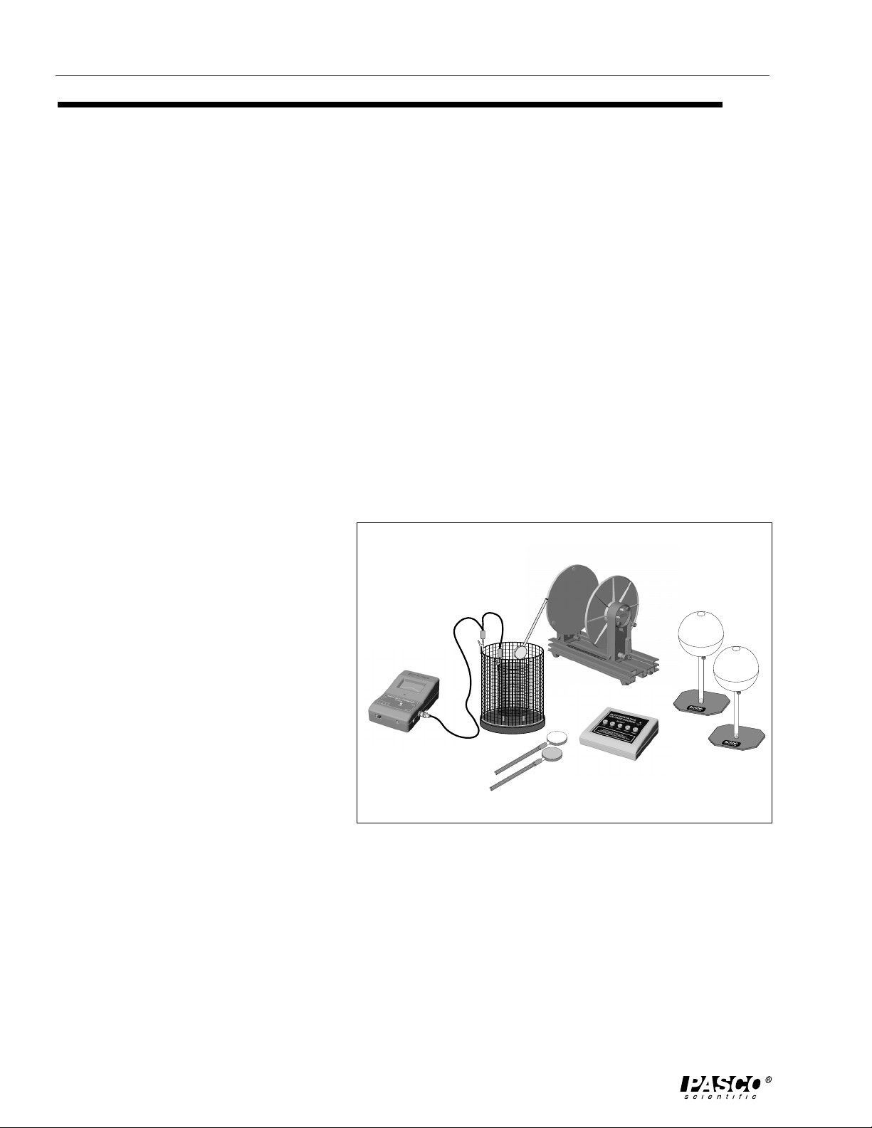
Theory
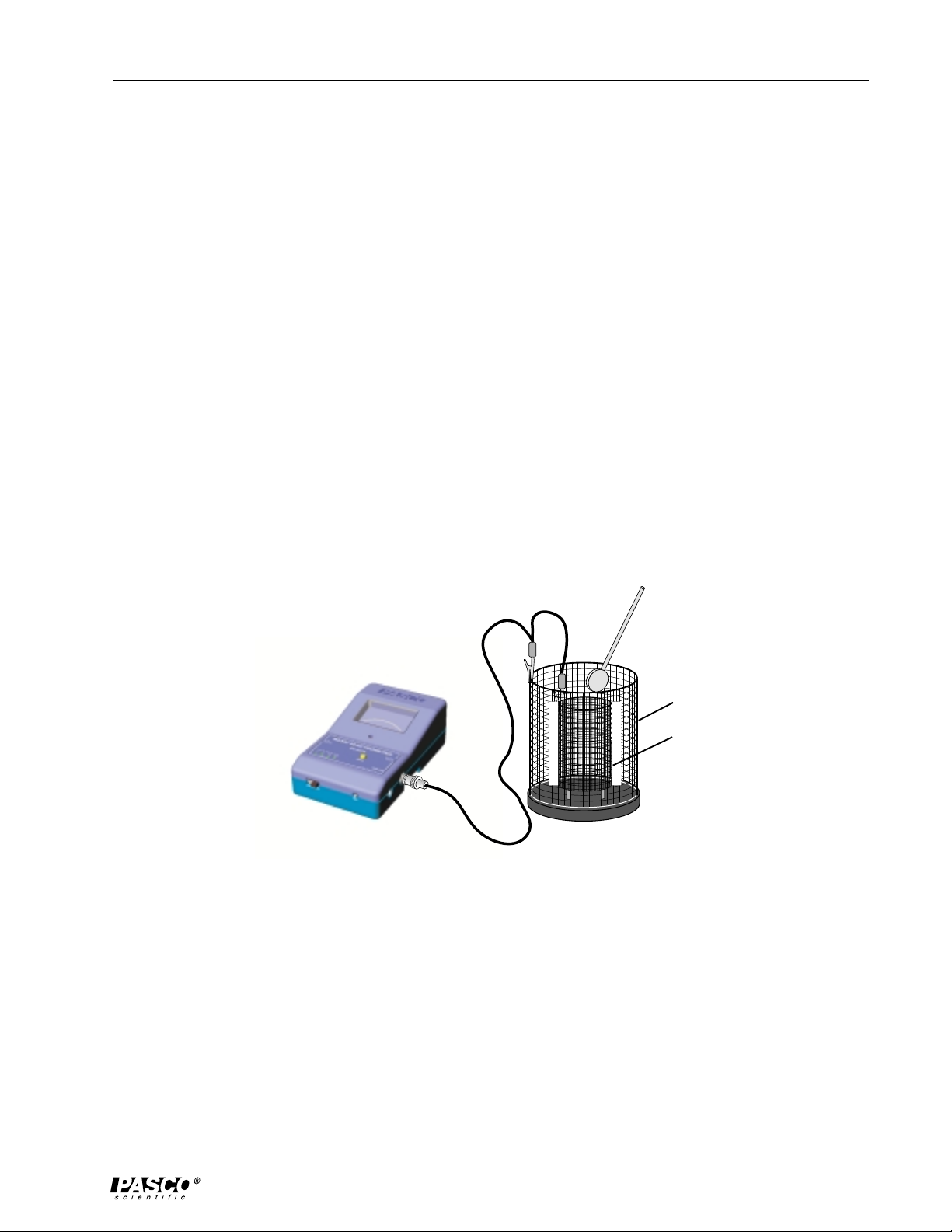
ES-9042A Faraday Ice Pail
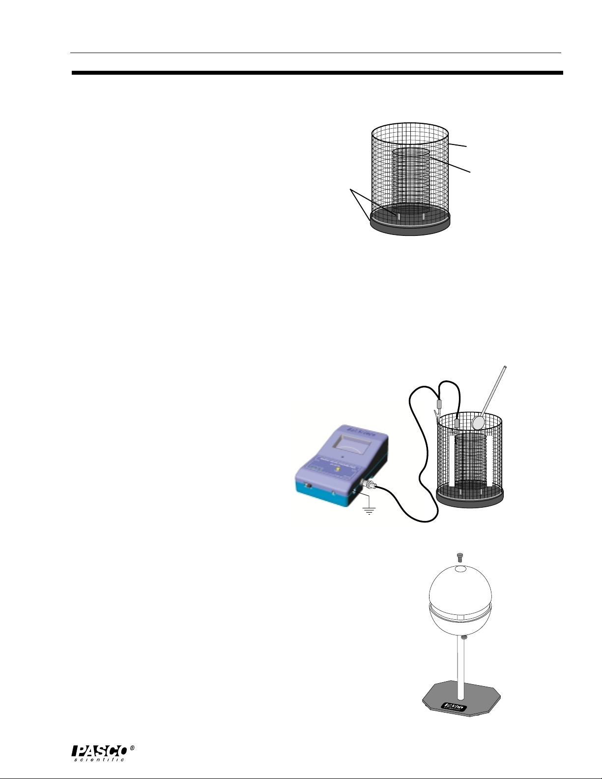
The PASCO Faraday Ice Pail (ES-9042A) is shown
in Figure 1. Originally designed by Michael Faraday,
it works on the principle that any charge placed
inside a conducting surface will induce an equal
charge on the outside of the surface. It is an excellent
product for sampling charges and charge
distributions. The PASCO version illustrated above
consists of two wire mesh cylinders, one inside the
other, mounted on a molded plastic bottom.
The outer cylinder is called the shield. It provides
complete visibility to the inside of the pail and, when grounded, helps eliminate
stray charges and AC fields. The inner cylinder is the actual pail. Notice how the pail
is mounted on insulated rods. The pail is 10 cm in diameter and 15 cm high. When a
charged object is placed inside the pail, but without touching it, a charge of the same
magnitude is induced on the outside of the pail. (See Figure 2). An electrometer
connected between the pail and the shield
will detect a potential difference. The
greater the charge, the greater the potential
difference. So even though the
electrometer will give readings of voltage,
it is possible to use those values as relative
charge measurements.
To prevent stray charges from producing
erroneous results, it is extremely important
that the Ice Pail be momentarily grounded
prior to starting any experiment. The
demonstrator must also be continually
grounded while performing an experiment.
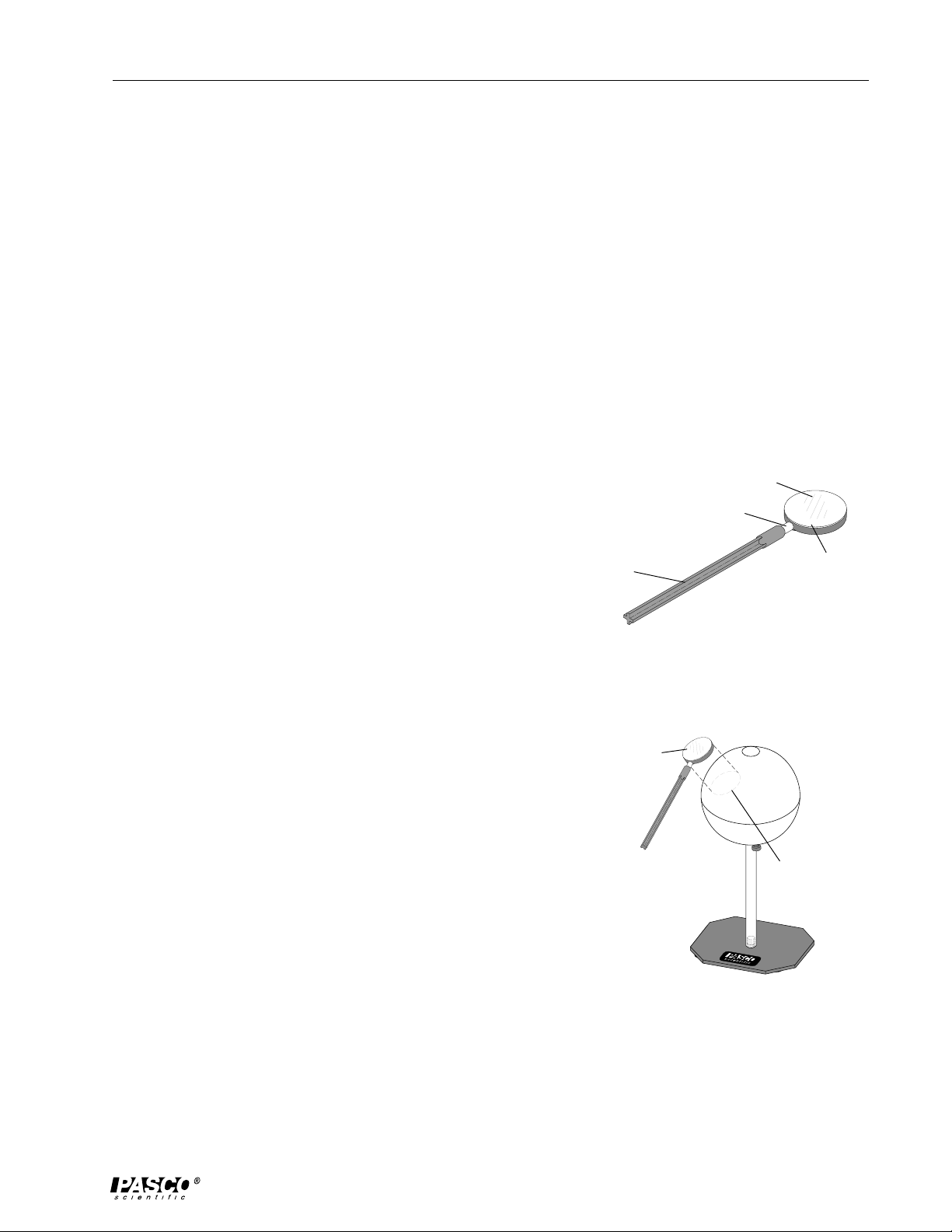
Other accessories included with this system are the Charge
Producers and the Proof Planes (PASCO ES-9057B). The Charge
Producers are used as charged objects to lower into the Ice Pail.
The Proof Planes are used to sample surface charge densities.
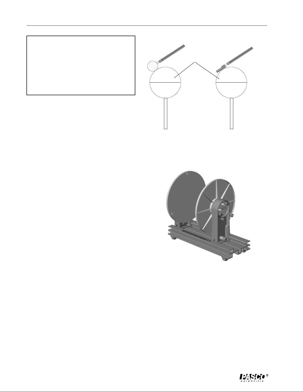
ES-9059B 13-cm Spheres
The conductive spheres are used to store electrical charge. The
PASCO Model ES-9059B spheres are composed of plastic resin
mold plated with a copper base, outer plating of non-sulphur brite
nickel, with final plating of chrome. The spheres are mounted on
insulting polycarbonate rods, attached to a support base. Each
sphere has a thumb-nut on the lower half that can be used for
attaching a ground cable or a lead from a power supply. The
Figure 1. Faraday Ice Pail
!
!
!
!
!
!
!
!
!
!
"
"
"
"
"
"
"
"
Figure 2. Charge induction
Figure 3. Conductive Sphere
insulators
shield
pail