manuals.online logo
Brands
  1. Home
  2. •
  3. Brands
  4. •
  5. PASCO
  6. •
  7. Laboratory Equipment
  8. •
  9. PASCO CI-6512 User manual

PASCO CI-6512 User manual

RLC Circuit
Introduction
The RLC Circuit board is designed to be used with a PASCO
850 or 550 Universal Interface to study the behavior of
resistors, inductors, and capacitors in an AC circuit. The board
includes three resistors, two capacitors, an air-core inductor, a
#50 miniature screw lamp, and a bi-color LED. The included
steel rod can be used to increase the inductance of the inductor
by placing the rod inside the coil.
NOTE: Prior to the first use, remove the bolt that secures
the inductor during shipping.
Inductor
An air core inductor with an inductance of
8.2 mH.
1
Steel Rod
For placing inside the inductor to increase the
inductance.
2
Resistors
Includes three resistors with a resistance of
100 Ω, 33 Ω, and 10 Ω.
3
Lamp
A replaceable #50 miniature screw base lamp.
4
LED
A bi-color LED in series with a 150 Ω resistor.
The illuminated color is dependent on the
polarity of the connection.
5
Capacitors
Includes two electrolytic capacitors with a
capacitance of 330 µF and 100 µF.
6
CI-6512 RLC Circuit Product Manual
012-04818E Page 1 of 4
Required Equipment
The equipment listed below is required for performing
experiments with the CI-6512 RLC Circuit.
PASCO Universal Interface
The UI-5000 850 Universal Interface or the UI-5001 550
Universal Interface supplies a power to the circuit using
its integrated signal generator and connections for
sensors. The signal generator is capable of reporting the
output voltage, current, and frequency of the signal.
Voltage Sensor
A voltage sensor is required to measure the voltage across
a single component in the circuit. Use either the UI-5100
Unshrouded Voltage Sensor or the UI-5110 Shrouded
Voltage Sensor.
Banana Plug Patch Cords
Cords are required to connect the RLC Circuit to the
Universal Interface. Patch cords are available from
PASCO in the following lengths:
• 15 cm (EM-9737)
• 30 cm (SE-7123)
• 75 cm (SE-9750, SE-9751, EM-9740, EM-9745)
• 200 cm (SE-9415A)
PASCO Data Collection Software
PASCO Capstone or SPAR vue software is required for
data collection and to control the signal output of the
Universal Interfaces. The 850 Universal Interface can
only be used with PASCO Capstone.
Circuit Setups
Though the name of this product is called "RLC Circuit," it is
possible to also create RC and LR circuits with the apparatus.
Additionally, it is possible to apply signals to each component
individually on the board.
RLC Circuit Setup
The resistors, capacitors, and inductor are connected in series
on the RLC Circuit board. To create an RLC circuit:
1. Connect the ground port of the signal generator to the
banana jack of a resistor.
2. Connect the signal generator port to the banana jack of a
capacitor.
Below is an example RLC circuit which contains a 10 Ω
resistor, a 330 µF capacitor, and the inductor.
Figure 1. An RLC circuit example
RC Circuit Setup
The resistors, capacitors, and inductor are connected in series
on the RLC Circuit board. In order to create an RC circuit,
a cable must be connected across the inductor to bypass the
inductor. To create an RC circuit:
1. Connect the ground port of the signal generator to the
banana jack of a resistor.
2. Connect the signal generator port to the banana jack of a
capacitor.
3. Connect a banana cable to each jack of the inductor.
Below is an example RC circuit which contains a 10 Ω resistor
and 330 µF capacitor.
Figure 2. An RC circuit example
CI-6512 RLC Circuit Product Manual
012-04818E Page 2 of 4
LR Circuit Setup
Each resistor is connected in series with the inductor on the
RLC Circuit board. To create an LR circuit:
1. Connect the ground port of the signal generator to the
banana jack of a resistor.
2. Connect the signal generator port to the banana jack
shared by the inductor and capacitors.
Below is an example LR circuit which contains a 10 Ω resistor
in series with the inductor.
Figure 3. An LR circuit example
Single Component Setup
It is possible to connect a single component to the signal
generator on the Universal Interface. This can be useful for
performing an Ohm's Law experiment where the current
through a single resistor is measured as the voltage across it is
changed. To connect a single component:
1. Connect the ground port of the signal generator to the
banana jack of a component.
2. Connect the signal generator port to the banana jack on the
opposite end of the component.
The below example shows a single 10 Ω resistor connected to
the signal generator.
Figure 4. A single component connection example
Specifications
Maximum
Working Voltage
10 V
Resistors 100 Ω ± 5%, 1 W
33 Ω ± 5%, 5 W
10 Ω ± 5%, 10 W
Capacitors 100 µF ± 20 %, 16 V
330 µF ± 20 %, 16 V
Inductor 8.2 mH @ 1 kHz
6.5 Ω maximum DC resistance
0.8 A current rating RMS
0.75" ID X 1.75" OD
Lamp 7.5 V, 0.22 A, #50 miniature screw style
LED red (655 nm)/green (565 nm)
1.7–2.1 V typical forward voltage
1.5 mcd average brightness @ 20 mA
CI-6512 RLC Circuit Product Manual
012-04818E Page 3 of 4
Technical Support
For assistance with any PASCO product, contact PASCO
Technical Support.
Address PASCO scientific
10101 Foothills Blvd.
Roseville, CA 95747-7100
Phone 1-800-772-8700 (USA)
1-916-462-8384 (International)
Chat www.pasco.com
email [email protected]
Product End of Life Disposal Instructions
This electronic product is subject to disposal and recycling
regulations that vary by country and region. It is your
responsibility to recycle your electronic equipment per your local
environmental laws and regulations to ensure that it will be
recycled in a manner that protects human health and the
environment. To find out where you can drop off your waste
equipment for recycling, please contact your local waste recycle or disposal
service, or the place where you purchased the product.
The European Union WEEE (Waste Electronic and Electrical Equipment)
symbol and on the product or its packaging indicates that this product must not
be disposed of in a standard waste container.
Warranty, Copyright, and Trademarks
Limited Warranty: For a description of the product warranty, see the
Warranty and Returns page at www.pasco.com/legal.
Copyright: This document is copyrighted with all rights reserved. Permission
is granted to non-profit educational institutions for reproduction of any part
of this manual, providing the reproductions are used only in their laboratories
and classrooms, and are not sold for profit. Reproduction under any other
circumstances, without the written consent of PASCO scientific, is prohibited.
Trademarks: PASCO and PASCO scientific are trademarks or registered
trademarks of PASCO scientific, in the United States and/or in other countries.
All other brands, products, or service names are or may be trademarks or
service marks of, and are used to identify, products or services of, their
respective owners. For more information visit www.pasco.com/legal.
CI-6512 RLC Circuit Product Manual
012-04818E Page 4 of 4

Other PASCO Laboratory Equipment manuals

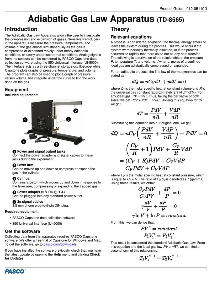
PASCO TD-8570A User manual

PASCO

PASCO TD-8570A User manual

PASCO AP-8219 User manual

PASCO

PASCO AP-8219 User manual
PASCO ME-9889 User manual

PASCO

PASCO ME-9889 User manual

PASCO ME-9207B User manual

PASCO

PASCO ME-9207B User manual

PASCO TD-8565 User manual

PASCO

PASCO TD-8565 User manual

PASCO EM-6720 User manual

PASCO

PASCO EM-6720 User manual
PASCO CI-6538 User manual

PASCO

PASCO CI-6538 User manual

PASCO ME-8971 User manual

PASCO

PASCO ME-8971 User manual

PASCO ES-9059C User manual

PASCO

PASCO ES-9059C User manual

PASCO ME-6841 User manual

PASCO

PASCO ME-6841 User manual

PASCO PK-9023 User manual

PASCO

PASCO PK-9023 User manual

PASCO ME-6810A User manual

PASCO

PASCO ME-6810A User manual

PASCO ME-8594 User manual

PASCO

PASCO ME-8594 User manual

PASCO ES-9047 User manual

PASCO

PASCO ES-9047 User manual

PASCO ME-9454 User manual

PASCO

PASCO ME-9454 User manual

PASCO AP-8210A User manual

PASCO

PASCO AP-8210A User manual

PASCO PS-2600A User manual

PASCO

PASCO PS-2600A User manual

PASCO PS-3401 User manual

PASCO

PASCO PS-3401 User manual

PASCO SE-9638 User manual

PASCO

PASCO SE-9638 User manual
PASCO SE-3607 User manual

PASCO

PASCO SE-3607 User manual

PASCO PASCObot Gripper PS-3325 User manual

PASCO

PASCO PASCObot Gripper PS-3325 User manual

PASCO AP-8214 User manual

PASCO

PASCO AP-8214 User manual

PASCO TD-8498A User manual

PASCO

PASCO TD-8498A User manual

PASCO ME-5707A User manual

PASCO

PASCO ME-5707A User manual

Popular Laboratory Equipment manuals by other brands

De La Rosa Research 31202A user manual

De La Rosa Research

De La Rosa Research 31202A user manual

Cypress Diagnostics CYANExpert 130 user manual

Cypress Diagnostics

Cypress Diagnostics CYANExpert 130 user manual

Hirschmann Pipetus instruction manual

Hirschmann

Hirschmann Pipetus instruction manual

Elmi DOS-20M user manual

Elmi

Elmi DOS-20M user manual

DEMA 700 Series owner's manual

DEMA

DEMA 700 Series owner's manual

Data Harvest 1112 manual

Data Harvest

Data Harvest 1112 manual

Macherey-Nagel NucleoMag SEP user manual

Macherey-Nagel

Macherey-Nagel NucleoMag SEP user manual

CLIMET INSTRUMENTS CI-154 user manual

CLIMET INSTRUMENTS

CLIMET INSTRUMENTS CI-154 user manual

Millipore PR00SIA1 Replacement procedure

Millipore

Millipore PR00SIA1 Replacement procedure

NEW BRUNSWICK SCIENTIFIC C2 Classic Guide to operations

NEW BRUNSWICK SCIENTIFIC

NEW BRUNSWICK SCIENTIFIC C2 Classic Guide to operations

Ametek TAYLOR HOBSON FORM TALYSURF PGI NOVUS Operator's guide

Ametek

Ametek TAYLOR HOBSON FORM TALYSURF PGI NOVUS Operator's guide

Fisherbrand Accu500 instruction manual

Fisherbrand

Fisherbrand Accu500 instruction manual

Hanil Supra R30 quick guide

Hanil

Hanil Supra R30 quick guide

Campbell SkyVUE 8M Quick Deploy Guide

Campbell

Campbell SkyVUE 8M Quick Deploy Guide

HunterLab ColorFlex EZ Coffee user manual

HunterLab

HunterLab ColorFlex EZ Coffee user manual

Chopin Mixolab 2 Maintenance manual

Chopin

Chopin Mixolab 2 Maintenance manual

Sartorius Cubis MCA2.7S operating instructions

Sartorius

Sartorius Cubis MCA2.7S operating instructions

Environmental Express 35419-52 instruction manual

Environmental Express

Environmental Express 35419-52 instruction manual

manuals.online logo
manuals.online logoBrands
  • About & Mission
  • Contact us
  • Privacy Policy
  • Terms and Conditions

Copyright 2025 Manuals.Online. All Rights Reserved.