PASCO ME-6843 User manual

800-772-8700 www.pasco.com
®Instruction Manual
012-09924A
Spring Cart Launcher
ME-6843
Included Equipment Quantity Replacement Part Number
Spring Cart Launcher 1 ME-6843
Firm Spring (black) 1
ME-68471
1ME-6847 replacement kit includes (2) of each spring and (4) release pins
Medium Spring (blue) 1
Soft Spring (red) 1
Release Pin 2
String 1 m
Required Equipment Part Number
Cart2
2This part is included in many of the PASCO dynamics systems. See PASCO catalog or www.pasco.com for details.
1 ME-6951, ME-6950, ME-9430, or ME-9454
Tra ck21 ME-6953 or similar
End Stops3
3New-style plastic end stops required. These are included with PASCO dynamics systems starting in 2007.
2 ME-9469 (2-pack)
Recommended Equipment
250 g Compact Cart Mass 2 ME-6755
For sensor-based method:
Motion Sensor4
4PASPORT sensors require a PASPORT interface. See PASCO catalog or www.pasco.com for details.
1 PS-2103
Force Sensor41 PS-2104
For traditional method:
Super Pulley with Clamp 1 ME-9448A
Hooked Mass Set 1 SE-8759 or similar

®
Spring Cart Launcher Introduction
2
End stops
Pull
up
Introduction
The Spring Cart Launcher is designed for the study of force and motion, potential
energy, conservation of energy, the work-energy theorem, Hooke’s Law, and spring
constants. Use it to launch any PASCO dynamics cart by compressing and releasing
one of three interchangeable springs. The included release pin, in combination with
two end stops, allows you to use precisely the same spring compression for multiple
launches.
This manual includes instructions for a sensor-based experiment (page 4) using
motion and force sensors, and a traditional experiment (page 6) using hanging masses
and an inclined track.
Set-up and Launch
For this general set-up, you will need the Spring Cart
Launcher with its included springs, launch pin, and string; a
cart; a track, and two adjustable end stops.
1. Fit the Spring Cart Launcher onto
the top of the cart (as illus-
trated). Tighten the
thumbscrews to secure it.
2. Select one of the included springs. Slide it onto the launcher
shaft with the flared end out. Turn the spring to secure the end in
the spring retention hole as illustrated.
3. Tie the string to the release pin.
4. Install two end stops near one end of a dynamics track between 3
cm and 10 cm apart, measured center-to-center.
5. Place the cart on the track. Push the launcher shaft through the
holes in both end stops.
6. Insert the release pin through
the hole in the end of the
launcher shaft. Allow the
launch pin to rest against the
end stop.
7. To launch the cart, jerk the
launch pin out by pulling
sharply up on the string.
As a simpler, but less repeatable, alternative to the above set-up, use only one end
stop and do not use the launch pin. Pull the shaft through the end stop and release it
from your hand.
Flared
end
Spring
retention
hole
Release pin String
Thumbscrews

®
Model No. ME-6843 Cart Mass
3
Cart Mass
For varying the mass of the cart, the Spring Cart Launcher is designed to hold one or
two Compact Cart Masses (PASCO part ME-6755). The launcher prevents these
masses from shifting or sliding. Place the masses as illustrated.
Theory
The spring constant of a spring is
(eq. 1)
where Fxis the force applied to the spring and xis the displacement of the end of the
spring from its equilibrium position.
As you push the end of a spring (or anything else) from position x1to x2, the work that
you do is equal to the area under the Fxversus xgraph, or
(eq. 2)
The potential energy stored in a spring is
(eq. 3)
The kinetic energy of a cart moving on a track is
(eq. 4)
where mis the mass of the cart, and Vis the magnitude of velocity.
The change in gravitational potential energy of a cart moving up an inclined track is
(eq. 5)
where g= 9.8 m/s2, ∆sis the distance traveled along the track (in the uphill direction),
and θis the track’s angle of incline.
Masses
kFx
x
------= Spring constant
WF
xxd
x1
x2
∫
=Work done on a spring
Uspring
1
2
---kx2
=Potential energy stored in
a spring
K1
2
---mV2
=Kinetic energy
∆Ugravity mg∆sθsin=Potential energy of a cart
on an inclined track

®
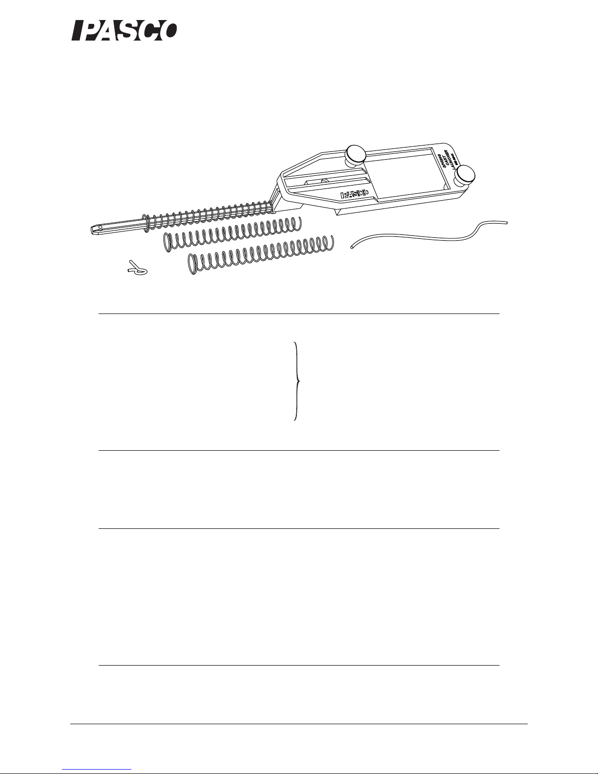
Spring Cart Launcher Sensor-based Experiment
4
Sensor-based Experiment
Note About Sensors and Interfaces
In this experiment, a force sensor measures the force that you apply to the spring; a
motion sensor measures the displacement of the end of the spring as it is compressed,
the position of the cart, and the velocity of the cart.
You can use the PASPORT sensors recommended on page 1 with a multiple-port
interface (such as an Xplorer GLX or Power Link) or two single-port interfaces (such
as USB Links). Most of the measurements described below can also be done with just
one single-port interface using one sensor at a time. ScienceWorkshop sensors and
interfaces would also work.
The instructions below refer to operations in DataStudio software such as connecting
sensors, setting sampling rates, and setting up graphs. For information about these
tasks, press F1 to open DataStudio Help. This experiment can also be done on the
Xplorer GLX in standalone mode (without a computer).
Additional Set-up
1. Follow set-up steps 1 through 3 on page 2.
2. Install one end stop on the track. If you are using a 1.2 m track, place the end stop
near one end. If you are using a 2.2 m track, place the end stop in the middle.
3. Level the track so that the cart does not roll when release from a standstill.
4. Clip the motion sensor to the end of the track opposite from the end stop. Aim the
sensor along the track. Set the range switch to the NEAR or cart setting.
5. Connect the motion sensor and a force sensor to your PAPORT interface (or
interfaces). If you are using a computer, connect the interfaces to it and start
DataStudio.
6. Set the sampling rate of both sensors to 20 Hz.
7. Prepare the following graphs: Position versus Time, Velocity versus Time, Posi-
tion versus Force (Pull Positive).
Spring Constant, Work, and Spring Potential Energy
In this part you will use Equation 1 to determine kfor your spring. The force sensor
measures Fx, and the motion measures x. The slope of the Fxversus xgraph equals k.
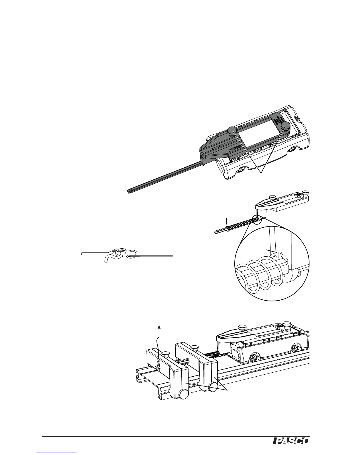
1. Place the cart on the track
with the launcher shaft
through the hole in the
end stop.
2. Use a piece of string to tie
the hook of the force sen-
sor to the launcher shaft.
3. Pull back with the force sensor so that the end of the spring just touches the end
stop, but do not compress the spring yet.
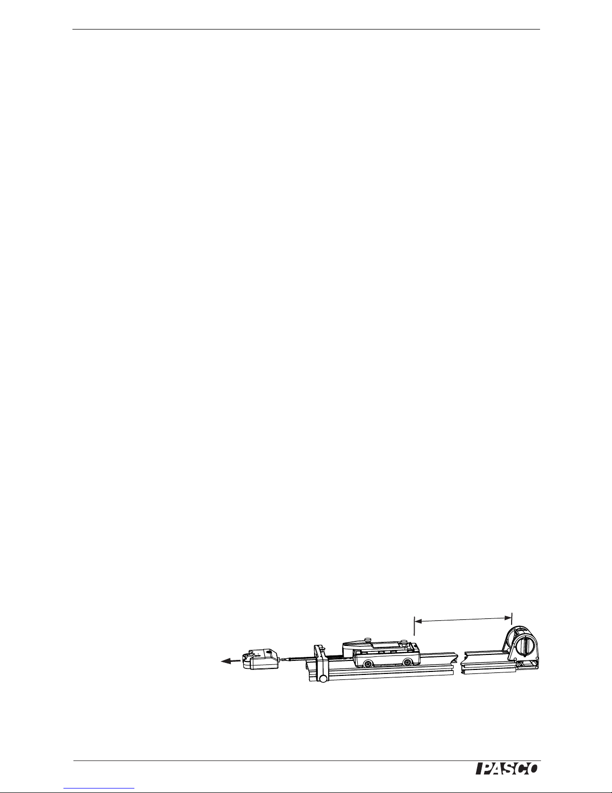
~1 m
Pull
Force sensor Motion sensor

®
Model No. ME-6843 Sensor-based Experiment
5
Spring Compression
Release
4. Press the ZERO or TARE button on the force sensor.
5. Start data recording.
6. Slowly pull back with the force sensor until the spring is almost completely com-
pressed.
Note: Have your partner hold the track to prevent it from slipping, but be careful not to block
the motion sensor.
7. Stop data recording.
8. Determine kfrom the slope of the Fxversus xgraph.
9. Measure the area under graph. This area equals the work, W, that you did on the
spring.
10. From the graph, determine the displacement (or change in position) of the end of
the spring.
11. Use Equation 3 to calculate Uspring, the potential energy stored in the spring after
you compressed it.
12. Compare Wto Uspring. Do both values have the same (or equivalent) units? What
is the percent difference?
13. Repeat steps 1 through 8 to determine the spring constants of all three springs.
Untie the string from the launcher shaft for the next part.
Spring Potential Energy and Kinetic Energy
In this part, you will study the relationship between the potential energy initially
stored in the spring and the kinetic energy of the cart just after launch.
1. Place a second end stop on the track about 8 cm behind the first end stop.
2. Place the cart on the track with the launcher shaft through the hole in the first end
stop. Position the cart so that the spring is touching the end stop but not com-
pressed.
3. Start data recording.
4. Wait a few seconds (to let the sensor measure the uncom-
pressed position). Push the shaft through both and stops and
put the release pin into the shaft. Let the pin rest against the
second end stop and wait a few more seconds (to let the sen-
sor measure the compressed position).
Important: In the next step, have your partner catch the cart before it
hits the motion sensor.
5. Pull out the release pin with a quick jerk to launch the cart
6. Stop data recording.
7. Determine the spring compression from the graph of position
versus time.

®
Spring Cart Launcher Traditional Experiment
6
8. Use the value of kthat you found in the previous part and Equation 3 to calculate
Uspring.
9. Look at the graph of velocity versus time to find the velocity of the cart just after
the launch.
10. Measure the mass of the cart with the launcher and spring attached.
11. Use Equation 4 to calculate the kinetic energy of the cart.
12. Compare the initial potential energy of the spring to the kinetic energy of the cart.
Are they equal? If not, what might account for the difference?
Traditional Experiment
In this experiment (which does not require sensors), you will determine the spring
constant by using a hanging mass to apply a known force. To determine the energy
transferred to the cart, you will observe the maximum height that the cart reaches as it
runs up an inclined track.
Spring Constant
1. Follow set-up steps 1
through 3 on page 2.
2. Install an end stop about 20 cm from the end of the track.
3. Clamp a pulley to the same end of the track.
4. Position the track so that a mass hanging from the pulley is free to hang over the
edge of your lab bench.
5. Level the track so that the cart does not roll when release from a standstill.
6. Place the cart on the track with the launcher shaft through the hole in the end
stop.
7. Tie a piece of string (about 40 cm long) to the launcher shaft. Run the string over
the pulley and hang a 100 g mass from the string.
8. Adjust the pulley so that the string is horizontal between the pulley and the
launcher shaft.
9. In a table, record the position of the cart on the track and the total mass hanging
from the string.
10. Add 100 g to the hanging mass.
11. Repeat steps 9 and 10 up to about 500 g.
12. Calculate the force applied to the spring at each step: Fx= mhg, where mhis the
hanging mass and g= 9.8 m/s2.
13. Make a graph of Fxversus cart position.
14. Draw a best-fit line on your graph. The slope of that line equals the spring con-
stant, k.

®
Model No. ME-6843 Traditional Experiment
7
Untie the string from the launcher shaft and remove the pulley for the next part.
Spring Potential Energy and Kinetic Energy
1. Place a second end stop on the track about 8 cm behind the first end stop.
2. Elevate one end of the track by about 20 cm.
3. Hold the cart on the track with the launcher shaft through the hole in
the first end stop, and with the spring just touching the end stop, but
not compressed. Record this position of the cart as x1.
4. Push the shaft through both and stops and put the release pin into the shaft. Let
the pin rest against the second end stop. Record this position of the cart as x2.
5. Pull out the release pin with a quick jerk.
6. Watch the cart carefully as it ascends the track. Observe the highest position
achieved. Try to read it to the nearest centimeter. Record this position as x3.
7. Calculate the spring compression: x= x1- x2
8. Use x, the value of kthat you found in the previous part, and Equation 3 to calcu-
late the initial potential energy of the spring.
9. Calculate the distance traveled by cart: ∆s= x3- x2
10. Measure the mass, m, of the cart with the cart launcher and spring attached.
11. Measure the angle, θ, of the track.
12. Use Equation 5 to calculate the change in gravitational potential energy of the
cart.
13. Compare the initial potential energy of the spring to the maximum gravitational
potential energy of the cart. Are they equal? If not, what might account for the
difference?
q

®
Spring Cart Launcher Other Suggested Experiments
8
Other Suggested Experiments
Launch from a Force Sensor
Set up an end stop, a force sensor, and the release pin as illustrated. While recording
motion- and force-sensor data, pull the force sensor to compress the spring; then jerk
out the release pin to launch the cart. In this way, you can record compression dis-
tance, spring force, and launch velocity in a single data run.
Launch from a Hanging Mass
Important: Do not use precision masses in this activity. Instead, use a small sandbag or other
object that will not be damaged when dropped.
Set up an end stop, a Super Pulley, a string, and the release pin as illustrated. Hang an
object of known mass (up to about 500 g) from the string. Jerk the pin out to launch
the cart. The spring force is equal to the weight of the hanging object.
Collision with a Fixed Object
Set up a track with an end stop at one end and a motion sensor at the other end. Set the
sampling rate to 50 Hz. Start data recording. Give the cart a push to make it roll along
the track and bounce off the end stop. Stop data recording.
Hold the cart stationary with the spring just touching the end stop and record a second
data run to measure the “zero-compression” position.
Use the velocity data to determine the kinetic energy of the cart before and after the
collision. Use the position data to determine the maximum spring compression (that
is, the maximum position measured during the collision minus the position measured
when the spring was just touching the end stop). From the compression distance, cal-
culate the maximum potential energy stored in the spring.
In this collision, energy is transferred from kinetic energy to potential energy and
back to kinetic energy. At each step, how much energy is “lost?” Where does it go?
Velocity before
Velocity after
ero-compression
position
Maximum
compression

®
Model No. ME-6843 Specifications
9
Specifications
Technical Support
For assistance with any PASCO product, contact PASCO at:
Limited Warranty
For a description of the product warranty, see the PASCO catalog.
Copyright
The PASCO scientific 012-09924A
Spring Cart Launcher Instruction Manual
is copyrighted with all rights reserved. Permission is
granted to non-profit educational institutions for reproduction of any part of this manual, providing the reproductions are used only in
their laboratories and classrooms, and are not sold for profit. Reproduction under any other circumstances, without the written con-
sent of PASCO scientific, is prohibited.
Trademarks
PASCO, PASCO scientific, DataStudio, PASPORT, and ScienceWorkshop are trademarks or registered trademarks of PASCO scien-
tific, in the United States and/or in other countries. All other brands, products, or service names are or may be trademarks or service
marks of, and are used to identify, products or services of, their respective owners. For more information visit www.pasco.com/legal.
Launcher dimensions 31 cm × 5 cm × 4 cm
Shaft length 14 cm
Spring length 10 cm
Spring diameter 1 cm
Spring constants 142 ± 14 N/m (black)
112 ± 11 N/m (blue)
84 ± 8 N/m (red)
Address: PASCO scientific
10101 Foothills Blvd.
Roseville, CA 95747-7100
Phone: 916-786-3800 (worldwide)
800-772-8700 (U.S.)
Fax: (916) 786-7565
Web: www.pasco.com
Email: support@pasco.com
This manual suits for next models
1
Table of contents
Other PASCO Toy manuals
Popular Toy manuals by other brands

The Learning Journey
The Learning Journey Techno Gears Marble Mania Catapult manual

Hornby
Hornby CLASS 67 Operating and maintenance instructions

LeapFrog
LeapFrog Pick Up & Count Vacuum Parents' guide

ACME
ACME zoopa II glider instruction manual

Seagull Models
Seagull Models SEA 285 Assembly manual

Fisher-Price
Fisher-Price 78023 instructions