Paso B711-G User manual

α
Istruzioni per l’uso • Instructions for use • Manuel d’utilisation • Gebrauchsanleitung • Gebruiksaanwijzing • Instrucciones de uso
SOUND SYSTEM SPECIALIST
Postazioni da tavolo
Microphone stands
Bases microphoniques
Mikrofonbasis
Microfoonvoet
Bases microfonicas
Les agradecemos que hayan elegido un producto PASO y deseamos recordarles que
nuestra empresa trabaja con sistema de calidad certificado. Todos nuestros productos
son pues controlados en cada fase de la producción para garantizarles una plena
satisfacción en su adquisición. Para cualquier tipo de eventualidad la garantía cubrirá,
durante el periodo de validez, eventuales defectos de fabricación. Les aconsejamos
que lean detenidamente y se ajusten a las siguientes instrucciones de uso, para utilizar
correctamente este producto y aprovechar al máximo sus prestaciones.
Wij danken u voor uw keuze van een PASO product en herinneren u eraan dat de
productie van ons bedrijf volgens een certificeerd kwaliteitssysteem plaatsvindt. Onze
producten worden daarom in iedere productiefase controleerd zodat u zeker tevreden
zult zijn met uw aankoop. Eventuele fabrieksfoutjes zijn in de periode dat de garantie
geldig is, gedekt. Voor een goed gebruik van dit product en voor een volledige benutting
van de prestaties hiervan, raden wij u aan onderstaande gebruiksvoorschriften met
aandacht door te lezen.
B711-G
B711/6-G
B711/12-G
Nel ringraziarVi per aver scelto un prodotto PASO, vogliamo ricordarVi che la nostra
azienda opera con sistema di qualità certificato. Tutti i nostri prodotti vengono pertanto
controllati in ogni fase della produzione per garantirVi la piena soddisfazione del Vostro
acquisto. Per ogni evenienza la garanzia coprirà, nel periodo di validità, eventuali difetti
di fabbricazione. Vi raccomandiamo di leggere attentamente le seguenti istruzioni d’uso
per sfruttare appieno le prestazioni offerte da questo prodotto e per evitare eventuali
problemi.
While thanking you for having chosen a PASO product, we would like to remind you that our
company works according to a certified Quality System. This means that all our products
are checked during every phase of manufacturing in order to ensure that you will be fully
satisfied with your purchase. In any case, the guarantee will cover any manufacturing flaws
during the guarantee period. We recommend that you read the following instructions for
use and follow them carefully in order to exploit in full the performance of this product
and use it correctly.
Vous remerciant d’avoir accordé votre préférence à un produit PASO, nous tenons à vous
rappeler que nous appliquons à notre production un Système Qualité certifié. Aussi, pour
donner entière satisfaction à notre clientèle, tous nos produits sont contrôlés à chaque
étape de la production. Ils sont en outre garantis contre tout défaut de fabrication pendant
toute la période de validité de la garantie. Nous vous recommandons de lire attentivement
les instructions d’installation et d’utilisation qui suivent; elles vous permettront d’obtenir le
maximum des prestations offertes par le produit et en outre d’éviter tout problème.
Wir danken Ihnen für die Wahl eines PASO-Produkts und möchten Sie daran erinnern, dass
wir mit einem zertifizerten anerkannten Qualitätssicherungssystem arbeiten. D.h., alle unsere
Produkte werden in jeder Fertigungsphase kontrolliert, um Ihre vollständige Zufriedenheit
zu gewährleisten. Während des Gültigkeitszeitraums deckt die Garantie auf jeden Fall
eventuell vorliegende Produktionsmängel ab. Wir empfehlen Ihnen, die hier vorliegende
Bedienungsanweisung aufmerksam zu lesen, um das Leistungsangebot des Produkts voll
nutzen zu können und um Probleme beim Gebrauch zu vermeiden.
Indice dei contenuti
1. Descrizione...........................2
2. Connessioni..........................2
3. Configurazione......................3
4. Uso ......................................5
Dati tecnici ...............................6
Table of contents
1. Description ...........................2
2. Connection ...........................2
3. Configuration ........................3
4. Use ......................................5
Technical data ..........................6
Sommaire
1. Description ........................... 2
2. Connexions........................... 2
3. Configuration........................ 3
4. Utilisation ............................. 5
Données techniques.................. 6
Inhaltsangabe
1. Beschreibung........................7
2. Anschlüsse ...........................7
3. Konfiguration........................8
4. Gebrauch............................ 10
Technische Daten .................. 11
Inhoud
1. Beschrijving..........................7
2. Aansluitingen........................7
3. Configuratie..........................8
4. Gebruik .............................. 10
Technische Gegevens ............. 11
Sumario
1. Descripción...........................7
2. Conexiones...........................7
3. Configuración .......................8
4. Uso .................................... 10
Datos técnicos ........................ 11

α
2
1. DESCRIZIONE
Le postazioni microfoniche preamplificate B711-G,
B711/6-G e B711/12-G sono caratterizzate da
un microfono elettrete. Sono in grado di funzionare
indifferentemente con alimentazione a 12 Vcc
o 24 Vcc, adattandosi così a qualsiasi esigenza
applicativa.
1.1 Riferimenti numerati
1. Pulsante di chiamata (a rilascio).
2. Tasto di chiamata (a ritenuta).
3. Led indicatore attivazione microfono.
4. Etichette zone.
5. Tasto di chiamata generale.
6. Tasti di chiamata zone.
7. Led zone.
8. Regolazione livello segnale microfonico.
9. Regolazione livello segnale di preavviso.
10. Connettore uscita audio.
11. Connettore ingresso audio.
12. Connettore zone 7÷12.
13. Connettore zone 1÷6.
1. DESCRIPTION
Les postes microphoniques préamplifiés B711-
G, B711/6-G et B711/12-G sont équipés d’un
microphone électrète. Ils fonctionnent aussi bien à
12 Vcc qu’à 24 Vcc et s’adaptent ainsi à n’importe
quelle exigence d’application.
1. DESCRIPTION
The preamplified microphone stations B711-G,
B711/6-G e B711/12-G feature an electret
microphone. They can run on a 12 Vdc or a 24 Vdc
power supply, making them able to adapt to any
application-related need.
1.1 Numbered references
1. Call button (hold-down type).
2. Call key (toggle type).
3. LED signalling activation of the microphone.
4. Zone labels.
5. All-call key.
6. Zone call keys.
7. Zone LED.
8. Microphone signal level control.
9. Warning signal level control.
10. Audio output connector.
11. Audio input connector.
12. Connector for zones 7 to 12.
13. Connector for zones 1 to 6.
1.1 Reférences numerotées
1. Bouton d’appel (à relâchement).
2. Touche d’appel (à retenue).
3. DEL signalant l’activation du microphone.
4. Étiquettes zones.
5. Touche d’appel général.
6. Touches d’appel zones.
7. DEL zones.
8. Réglage du niveau du signal microphonique.
9. Réglage du niveau du signal de préavis.
10. Connecteur sortie audio.
11. Connecteur entrée audio.
12. Connecteur zones 7÷12.
13. Connecteur zones 1÷6.
876543 2 1
Pin 8
Pin 1
12345678
Pin 1
Pin 8
T568A STANDARD T568B STANDARD
Pin Colore Colour Couleur Pin Colore Colour Couleur
1bianco/verde white/green blanc/vert 1bianco/arancio white/orange blanc/orange
2verde green vert 2arancio orange orange
3bianco/arancio white/orange blanc/orange 3bianco/verde white/green blanc/vert
4blu blue bleu 4blu blue bleu
5bianco/blu white/blue blanc/bleu 5bianco/blu white/blue blanc/bleu
6arancio orange orange 6verde green vert
7bianco/marrone white/brown blanc/marron 7bianco/marrone white/brown blanc/marron
8marrone brown marron 8marrone brown marron
B711-G B711/6-G B711/12-G
2. CONNESSIONI
I collegamenti delle postazioni sono effettuati
tramite cavi STP cat.5 diretti (cioè non incrociati
o ‘cross-cable’).
Gli standard EIA/TIA T568A e EIA/TIA T568B
prevedono per tali cavi (e relativi connettori tipo
RJ45) le seguenti piedinature e colorazione:
2. CONNEXIONS
Les connexions des postes sont réalisées à l’aide de
câbles STP cat. 5 directs (c’est-à-dire non croisés
ou ‘cross-cable’). Les standards EIA/TIA T568A
et EIA/TIA T5668B prévoient pour ces câbles
(et les connecteurs correspondants de type RJ45)
la coloration et les brochages suivants:
2. CONNECTIONS
The stations are connected by means of direct
Cat. 5 STP cables (no cross-cables). In accordance
with EIA/TIA standard T568A and EIA/TIA
standard T568B, the pin-out for these cables (and
their RJ45 connectors) and the colour codes are:
IN OUT
AUDIO
810 911
PTT LOCK
2
3
1
IN OUT
AUDIOZONE
1 6÷7 12÷
810 9111213
ALL
PTT LOCK
5
6
7
4
2
3
1
IN OUT
AUDIOZONE
1 6÷7 12÷
810 9111213
ALL
PTT LOCK
5
6
7
4
2
3
1

B711-G, B711/6-G, B711/12-G
3
Importante! Tutti i connettori devono
essere di tipo RJ45 schermato.
Tutte le postazioni dispongono di una presa di
ingresso AUDIO IN e di una presa d’uscita AUDIO
OUT. Le postazioni B711/6-G e B711/12-G
dispongono anche delle prese ZONE 1÷6 e ZONE
7÷12 da cui si prelevano le tensioni per il pilotaggio
dei relè di commutazione zone e/o di attivazione
allarme. Nelle tabelle sottostanti vengono elencate
le piedinature di questi connettori.
Important! All the connectors must be
shielded RJ45 type.
Each station has an AUDIO IN input socket and
an AUDIO OUT output socket. B711/6-G and
B711/12-G stations also have ZONE 1÷6 and
ZONE 7÷12 sockets from which the voltage for
driving the zone switching and/or alarm activation
relays is taken. The pin-outs of these connectors
are listed below.
Important! Tous les connecteurs doivent
être de type RJ45 blindé.
Tous les postes disposent d’une prise d’entrée
AUDIO IN et d’une prise de sortie AUDIO OUT.
Les postes B711/6-G et B711/12-G présentent
également des prises ZONE 1÷6 et ZONE 7÷12
d’où l’on prélève les tensions pour le pilotage des
relais de commutation des zones et/ou d’activation
de l’alarme. Les tableaux ci-après fournissent la
liste des brochages de ces connecteurs.
*
non collegato.
*
not connected.
*
pas connecté.
Pin Audio IN Audio OUT
1 Audio + Audio +
2 Audio - Audio -
3 GND GND
4 Precedenza IN Precedenza OUT
5 n.c* n.c.*
6 +Vcc +Vcc
7 Seriale + Seriale +
8 Seriale - Seriale -
Schermo GND GND
Pin ZONE 1÷6 ZONE 7÷12
1 Zona 1 Zona 7
2 Zona 2 Zona 8
3 Zona 3 Zona 9
4 Zona 4 Zona 10
5 Zona 5 Zona 11
6 +Vcc +Vcc
7 Zona 6 Zona 12
8 GND GND
Schermo GND GND
Pin Audio IN Audio OUT
1 Audio + Audio +
2 Audio - Audio -
3 GND GND
4 Precedence IN Precedence OUT
5 n.c* n.c.*
6+Vdc +Vdc
7 Serial + Serial +
8 Serial - Serial -
Shield GND GND
Pin ZONE 1÷6 ZONE 7÷12
1 Zone 1 Zone 7
2 Zone 2 Zone 8
3 Zone 3 Zone 9
4 Zone 4 Zone 10
5 Zone 5 Zone 11
6 +Vdc +Vdc
7 Zone 6 Zone 12
8 GND GND
Shield GND GND
Broche Audio IN Audio OUT
1 Audio + Audio +
2 Audio - Audio -
3 GND GND
4 Priorité IN Priorité OUT
5 p.c* p.c.*
6 +Vcc +Vcc
7 Série + Série +
8 Série - Série -
Blindage GND GND
Broche ZONES 1÷6 ZONES 7÷12
1 Zone 1 Zone 7
2 Zone 2 Zone 8
3 Zone 3 Zone 9
4 Zone 4 Zone 10
5 Zone 5 Zone 11
6 +Vcc +Vcc
7 Zone 6 Zone 12
8 GND GND
Blindage GND GND
Le tipologie di collegamento dipendono dalla
modalità di funzionamento prescelta (fare
riferimento ai paragrafi seguenti).
The types of connection depend on the manner of
operation that is chosen (see following sections). Le type de connexion varie en fonction du mode
de fonctionnement choisi (voir les paragraphes
suivants).
3. CONFIGURAZIONE
Le postazioni possono funzionare in miscelazione
tra loro oppure ad interblocco con la gestione di
due livelli di priorità. E’ inoltre possibile attivare
per ogni postazione un segnale di preavviso
(chime) con regolazione di volume posteriore.
I modelli B711/6-G e B711/12-G dispongono di
tasti di chiamata zone (rispettivamente 6 e 12 tasti)
e di tasto di chiamata generale. I tasti zone sono
anche programmabili per l’attivazione di allarmi
oppure possono essere disabilitati. Il livello del
segnale microfonico è regolabile posteriormente.
3. CONFIGURATION
The stations can function in the mixing mode with
one another or interlocked with management of
two priority levels. It is also possible to activate
a warning signal (chime) for each station, with
rear volume control. Models B711/6-G and
B711/12-G have zone call keys (6 and 12 keys
respectively) and an All-Call key. The zone keys
can also be programmed to activate alarms or they
can be disabled. There is a level control for the
microphone signal on the rear panel.
3. CONFIGURATION
Les postes peuvent fonctionner en mélange entre
eux ou bien par interblocage avec la gestion de
deux niveaux de priorité. Il est par ailleurs possible
d’activer un signal de préavis (chime) pour chaque
poste avec réglage du volume par l’arrière. Les
modèles B711/6-G et B711/12-G disposent
de touches d’appel de zones (6 et 12 touches
respectivement) et d’une touche d’appel général. Les
touches de zones sont également programmables
pour l’activation d’alarmes et peuvent aussi être
désactivées. Le niveau du signal microphonique
est réglable sur le panneau arrière.
3.1 Modalità MISCELAZIONE
In questa modalità le postazioni possono effettuare
liberamente chiamate e/o attivazioni di allarmi. I
collegamenti delle linee AUDIO OUT provenienti
da ogni postazione possono essere parallelati
ai morsetti dell’apparecchiatura di controllo
(collegamento a stella, fig. 3.1.1).
3.1 MIXING mode
In this mode the stations can make calls and/or
activate alarms as required. The connections of
the AUDIO OUT lines from each station can be
made in parallel to the terminals of the control unit
(star connection, Fig. 3.1.1).
3.1 Mode MÉLANGE
Dans ce mode, les postes peuvent effectuer
librement des appels et/ou des activations
d’alarmes. Les connexions des lignes AUDIO OUT
en provenance de chaque poste peuvent être mises
en parallèle sur les bornes de l’appareil de contrôle
(montage en étoile, fig. 3.1.1.).
Fig. 3.1.1
Collegamento a stella
Star connection
Montage en étoile
AUDIO
Z7÷Z12
Z1÷Z6
IN OUT
AUDIOZONE
1 6÷7 12÷IN OUT
AUDIOZONE
1 6÷7 12÷IN OUT
AUDIOZONE
1 6÷7 12÷

α
4
Fig. 3.2.1
Modalità Interblocco
Interlock Mode
Mode Interblocage
3.2 Modalità INTERBLOCCO
Le caratteristiche funzionali di questa modalità
sono:
- solo una postazione per volta può essere attiva;
durante l’attivazione sulle altre postazioni il led
(3) lampeggerà per indicare la condizione di
occupato; se la postazione attiva è configurata
in bassa priorità può essere disabilitata
dall’attivazione di una ad alta priorità.
- tutte le postazioni propongono alle uscite
ZONE 1÷6 e ZONE 7÷12 le attivazioni della
postazione chiamante; in questo modo sarà
sufficiente collegare all’apparecchiatura di
controllo i cavi di uscite ZONE 1÷6 e ZONE
7÷12 di una sola postazione.
- in caso di allarme attivato, la condizione sarà
visualizzata anche sulle altre postazioni; tutte
le postazioni con il corrispondente tasto di
allarme abilitato potranno disattivare l’allarme
in corso.
- per avere un funzionamento coerente del
sistema, è necessario che tutte le postazioni
siano programmate con la modalità interblocco
(scegliendo il livello di priorità per ogni
postazione) ed abbiano la stessa configurazione
dei tasti di allarme (scegliendo quali rendere
attivi);
N.B: nel caso si utilizzino sia postazioni
B711/6-G che B711/12-G, le prime
dovranno avere la stessa configurazione
dei primi 6 tasti delle B711/12-G.
3.2 INTERLOCK Mode
The functional features of this mode are the
following:
- Only one station can be active at a time. While
one station is active, the LED (3) on the other
stations will flash to indicate a “busy” condition.
If the active station is configured for low priority,
it can be disabled on activating a station with a
higher priority.
- All the stations offer activation of the calling
station on their ZONE 1÷6 and ZONE 7÷12
outputs. This means that it will be sufficient
to connect the ZONE 1÷6 and ZONE 7÷12
output cables from a single station to the
control unit.
-
When an alarm is activated, this condition will
be displayed also on the other stations. All the
stations with the corresponding alarm key enabled
will be able to de-activate the current alarm.
- For consistent operation of the system, it is
necessary to programme all the stations in the
interlock mode (choosing the required level of
priority for each station) and for all the alarm
keys to have the same configuration (choosing
which to activate);
N.B: if both B711/6-G stations and
B711/12-G stations are used, the former
must have the same configuration as the
first 6 keys of the B711/12-G stations.
3.2 Mode INTERBLOCAGE
Les caractéristiques fonctionnelles de ce mode
sont les suivantes:
- un seul poste peut être actif à la fois; pendant
qu’un poste est actif, la DEL (3) clignotera sur
les autres postes afin d’indiquer la condition
“occupée”; si le poste actif est configuré en basse
priorité, il peut être désactivé par l’activation d’un
poste à priorité élevée;
- tous les postes proposent aux sorties ZONE 1÷6
et ZONE 7÷12 les activation du poste appelant;
de cette façon, il suffira de brancher à l’appareil
de contrôle les câbles de sortie des ZONE 1÷6
et des ZONE 7÷12 d’un seul poste;
- en cas d’activation d’une alarme, la condition
sera affichée également sur les autres postes;
tous les postes pourront désactiver l’alarme
en cours à l’aide de la touche d’alarme
correspondante;
- pour un fonctionnement cohérent du système,
il faut que tous les postes soient programmés
avec le mode d’interblocage (en sélectionnant le
niveau de priorité de chaque poste) et aient la
même configuration pour les touches d’alarme
(en choisissant celles à activer);
REMARQUE: en cas d’utilisation aussi
bien des postes B711/6-G que des postes
B711/12-G, les premiers devront avoir la
même configuration que les 6 premières
touches des B711/12-G.
In alternativa la linea AUDIO OUT di una
postazione può essere inserita nella presa AUDIO
IN della postazione precedente (collegamento in
cascata o ‘daisy-chain’, figura 3.1.2). I collegamenti
delle linee ZONE 1÷6 e ZONE 7 ÷12 devono
invece essere parallelati ordinatamente ai morsetti
dell’apparecchiatura di controllo.
As an alternative, the AUDIO OUT line of a
station can be plugged into the AUDIO IN socket
of the station preceding it (cascade or daisy-chain
connection, Fig. 3.1.2). ZONE 1÷6 and ZONE
7÷12 lines, on the other hand, must be tidily
connected in parallel to the terminals on the
control unit.
En alternative la ligne AUDIO OUT d’un poste
peut être insérée dans la prise AUDIO IN du
poste précédent (branchement en cascade ou
‘daisy-chain’, fig. 3.1.2). Les connexions des lignes
ZONE 1÷6 et ZONE 7÷12 doivent par contre
être placées en parallèle par rapport aux bornes
de l’appareil de contrôle.
Fig. 3.1.2
Collegamento in cascata
Cascade connection
Branchement en cascade
AUDIO
Z7÷Z12
Z1÷Z6
IN OUT
AUDIOZONE
1 6÷7 12÷IN OUT
AUDIOZONE
1 6÷7 12÷IN OUT
AUDIOZONE
1 6÷7 12÷
IN OUT
AUDIO
IN OUT
AUDIOZONE
1 6÷7 12÷IN OUT
AUDIOZONE
1 6÷7 12÷
IN OUT
AUDIO
IN OUT
AUDIOZONE
1 6÷7 12÷IN OUT
AUDIOZONE
1 6÷7 12÷
AUDIO
Z1÷Z6
Z7÷Z12

B711-G, B711/6-G, B711/12-G
5
3.3 Setting the mode
1. Press the PTT and LOCK keys at the same
time, then power up the station by plugging
the cable into the AUDIO OUT socket.
2. The LED (3) will flash with a sequence indicating
the mode that has been set:
3.3 Configuration du mode
1. Appuyer simultanément sur les touches PTT
et LOCK puis mettre le poste sous tension en
insérant le câble dans la prise AUDIO OUT.
2. La DEL (3) émettra une série de clignotements
afin d’indiquer le mode actuellement
sélectionné:
3.3 Impostazione della modalità
1. Premere contemporaneamente i tasti PTT
e LOCK e quindi alimentare la postazione
inserendo il cavo alla presa AUDIO OUT.
2. Il led (3) emetterà una sequenza di lampeggi ad
indicare la modalità correntemente impostata:
L= numero di lampeggi L= Number of flashes L= nombre de clignotements
3. I led (7) daranno indicazione della funzionalità
correntemente impostata dei tasti a cui si
riferiscono:
- Spento: tasto di chiamata zona.
- Acceso: tasto invio allarme abilitato.
- Lampeggiante: tasto invio allarme
disabilitato.
4. Per modificare la modalità di funzionamento
della postazione, premere il tasto LOCK una
o più volte per avere il numero di lampeggi
del led relativo pari alla modalità prescelta; in
modo automatico si passerà dalla modalità 6
alla modalità 1.
5. Per modificare la funzionalità dei tasti di zona
premere il tasto di zona desiderato fino ad
ottenere la funzionalità desiderata.
6. Per uscire, salvando le impostazioni, premere
il tasto PTT; la postazione è immediatamente
pronta per l’uso.
4. To change the operating mode of a station,
press the LOCK key once or more to see the
number of flashes of the LED corresponding
to the chosen mode. The system will progress
from mode 6 to mode 1 automatically.
5. To change the function of a zone key, press the
zone key in question until the required function
is reached.
6. To exit saving the settings, press the PTT key.
The station is ready for immediate use.
4. Pour modifier le mode de fonctionnement
du poste appuyer sur la touche LOCK une
ou plusieurs fois pour que le nombre de
clignotements de la diode correspondante soit
égal au mode sélectionné; le passage du mode
6 au mode 1 aura lieu en mode automatique.
5 Pour modifier la fonctionnalité des touches de zone,
appuyer sur la touche de zone désirée jusqu’à ce
que la fonctionnalité désirée soit obtenue.
6. Pour quitter, en enregistrant les configurations,
appuyer sur la touche PTT; le poste est tout de
suite prêt à l’usage.
3. The LEDs (7) will indicate the current function
of the keys to which they refer:
- Extinguished: zone call key.
- Illuminated: alarm key enabled.
- Flashing: alarm key disabled.
3. Les DEL (7) indiqueront la fonctionnalité
actuellement sélectionnée pour les touches
auxquelles elles se réfèrent:
- Éteinte: touche d’appel de zone.
- Allumée: touche d’envoi alarme activée.
- Clignotante: touche envoi alarme
désactivée.
4. USO
4.1 Chiamata generale
(B711-G)
Premere, a scelta, il pulsante PTT od il tasto
LOCK per attivare la chiamata generale (con
attivazione del chime, se impostato) ed inviare il
messaggio tramite il microfono: l’accensione del
led (3) confermerà l’attivazione microfonica. Per
terminare, rilasciare il pulsante PTT o ripremere
il tasto LOCK: la disattivazione microfonica sarà
confermata dallo spegnimento del led.
4. USE
4.1 All Call
(B711-G)
Press the PTT button or the LOCK button
depending on your choice, to activate the All Call
function (activating the chime, if set), and use the
microphone to send your message. The LED (3) will
light up to confirm activation of the microphone. To
terminate the call, release the PTT button or press
the LOCK button again. The LED will extinguish to
confirm de-activation of the microphone.
4. UTILISATION
4.1 Appel général
(B711-G)
Appuyer sur le bouton PTT ou sur la touche LOCK
pour activer l’appel général (avec activation du
signal de préavis (chime), s’il est configuré) puis
envoyer le message à l’aide du microphone:
l’allumage de la DEL (3) confirmera l’activation
microphonique. Pour terminer, relâcher le bouton
PTT ou appuyer de nouveau sur la touche LOCK:
la désactivation microphonique sera confirmée par
l’extinction de la DEL.
- è possibile utilizzare anche le basi B711-G;
queste postazioni potranno effettuare solo
chiamate generali.
- le postazioni devono essere collegate in cascata
tra loro (‘daisy-chain’) con un massimo di due
linee derivate a partire dall’apparecchiatura di
controllo (fig. 3.2.1).
- It is also possible to use B711-G stations. These
stations will only be able to make All-call calls.
- The stations must be connected to one another in
a daisy-chain, with a maximum of two branched
lines from the control unit (Fig. 3.2.1).
- il est possible d’utiliser également les postes
B711-G; ces postes pourront effectuer
uniquement des appels généraux;
- les postes doivent être branchés en cascade
entre eux (‘daisy-chain’) avec un maximum de
deux lignes dérivées à partir de l’appareil de
contrôle (fig. 3.2.1).
4.1 Chiamata zone
(B711/6-G, B711/12-G)
1. Per effettuare una chiamata, selezionare le
zone interessate premendo i tasti relativi:
i led delle zone interessate si illumineranno
per confermare la scelta; per deselezionare
una zona ripremere il tasto con conseguente
spegnimento del relativo led.
2. Premendo il tasto ALL (chiamata generale)
si selezionano tutte le zone di chiamata (con
esclusione dei tasti di allarme); premendo
nuovamente il tasto ALL, con tutte le
zone selezionate, si avrà la deselezione
complessiva.
4.1 Zone calls
(B711/6-G, B711/12-G)
1. To make a call, select the required zones by
pressing the associated keys.
The LEDs of the selected zones will light up
to confirm your choice. To deselect a zone
press the key again. The associated LED will
extinguish.
2. If you press the ALL key (All Call), all the
call zones will be selected (excluding the
alarm keys). If you press the ALL key again,
with all the zones selected, they will all be
deselected.
4.1 Appel des zones
(B711/6-G, B711/12-G)
1. Pour effectuer un appel, sélectionner les
zones intéressées en appuyant sur les touches
correspondantes: les DEL des zones intéressées
s’éclaireront pour confirmer la sélection; pour
désélectionner une zone, appuyer de nouveau
sur la touche, ce qui aura pour effet d’éteindre
la DEL correspondante.
2. Appuyer sur la touche ALL (appel général)
pour sélectionner toutes les zones d’appel (à
l’exception des touches d’alarme); appuyer de
nouveau sur la touche ALL, lorsque toutes les
zones sont sélectionnées, pour procéder à la
désélection globale.
L(*) Mode Ding-Dong
1 Mélange -
2 Mélange oui
3 Interblocage avec basse priorité -
4 Interblocage avec basse priorité oui
5 Interblocage avec haute priorité -
6 Interblocage avec haute priorité oui
L(*) Mode Chime
1 Mixing -
2 Mixing yes
3 Interlock with low priority -
4 Interlock with low priority yes
5 Interlock with high priority -
6 Interlock with high priority yes
L(*) Modalità Din-Don
1 Miscelazione -
2 Miscelazione sì
3 Interblocco con bassa priorità -
4 Interblocco con bassa priorità sì
5 Interblocco con alta priorità -
6 Interblocco con alta priorità sì

α
6
DATI TECNICI TECHNICAL DATA DONNEES TECHNIQUES B711 B711/6 B711/12
Tipo di microfono Microphone type Type de microphone elettrete / elecret / électréte
N° zone selezionabili No. of selectable zones Zone selectionnables - 6 12
Alimentazione Power supply Alimentation 12 Vcc / 24 Vcc
Assorbimento a 12 Vcc1Absorption at 12 Vdc1Absorption à 12 Vcc140 mA 56 mA 72 mA
Assorbimento a 24 Vcc1Absorption at 24 Vdc1Absorption à 24 Vcc150 mA 62 mA 75 mA
Risposta in frequenza Frequency response Reponse en fréquence 100 ÷ 15.000 Hz
Livello audio (bilanciato) Audio level (balanced) Niveau audio (équilibrée) 1,2 Vrms*
Livello din-don Chime level Niveau ding-dong 0,8 Vpp*
Limitatore di dinamica Dynamics limiter Limiteur de dynamique si / yes / oui
Dimensioni (L x H x P) Dimensions (W x H x D) Dimensiones (L x H x P) 116 x 60 (416) x 200 mm
Peso Weight Poids 0,82 kg 0,85 kg 0,87 kg
3. La selezione zone è uno stato temporaneo: se
l’attivazione con i tasti PTT o LOCK non avviene
entro 5 secondi circa dall’ultima pressione di
tasto, la selezione sarà annullata e tutti i led-
zone si spegneranno.
4. Effettuata la selezione delle zone come sopra
descritto, premere, a scelta, il pulsante
PTT od il tasto LOCK per attivare la
chiamata (con attivazione del chime, se
impostato) ed inviare il messaggio tramite il
microfono: l’accensione del led (3) confermerà
l’attivazione microfonica. Per terminare,
rilasciare il pulsante PTT o ripremere il tasto
LOCK: la disattivazione microfonica sarà
confermata dallo spegnimento del led (3) e
dei led di chiamata zone (7).
N.B.: Premendo i tasti PTT o LOCK senza zone
selezionate, si attiverà una chiamata generale.
3. Zone selection is a temporary status: if activation
by means of the PTT or LOCK buttons does not
take place within about 5 seconds since the key
was last pressed, the selection will be cancelled
and all the zone LEDs will extinguish.
4. Once the zones have been selected as
described above, press the PTT button or
the LOCK button, depending on your choice,
to activate the call (with activation of the
chime, if set) and send your message through
the microphone. The LED (3) will light up
to confirm activation of the microphone. To
terminate the call, release the PTT button or
press the LOCK button again. The LED (3)
and the zone call LEDs (7) will extinguish to
confirm de-activation of the microphone.
N.B.: If you press the PTT or LOCK buttons
without selecting any zones, an ALL call will be
activated.
3. La sélection des zones est un état temporaire: si
l’activation avec les touches PTT ou LOCK n’a
pas lieu dans les 5 secondes après la dernière
touche appuyée, la sélection sera annulée et
toutes les DEL des zones s’éteindront.
4. Après avoir sélectionné les zones comme
cela est indiqué ci-dessus, appuyer - au choix
- sur le bouton PTT ou sur la touches LOCK
pour activer l’appel (avec activation du signal
de préavis (chime), s’il est configuré) puis
envoyer le message à l’aide du microphone :
l’allumage de la DEL (3) confirmera l’activation
microphonique. Pour terminer, relâcher le
bouton PTT ou appuyer de nouveau sur la
touche LOCK: la désactivation microphonique
sera confirmée par l’extinction de la DEL (3)
et des DEL d’appel des zones (7).
REMARQUE: Le fait d’appuyer sur le bouton
PTT ou sur la touche LOCK sans qu’aucune zone
ne soit sélectionnée aura pour effet d’activer un
appel général.
4.3 Attivazione allarmi
(
B711/6-G, B711/12-G
)
1. Premere il tasto configurato come allarme:
il relativo led lampeggerà velocemente per
segnalare la richiesta di conferma.
2. Entro un tempo di circa 3 secondi ripremere
lo stesso tasto per confermare ed attivare la
commutazione: il led segnalerà lo stato di
allarme con un lampeggio lento. In caso di
mancata conferma, lo stato di pre-allarme
viene annullato ed il led si spegnerà.
3. Per disattivare la commutazione di un allarme,
ripremere il tasto: per conferma, il relativo led
si spegnerà.
4.3 Alarms activation
(
B711/6-G, B711/12-G
)
1. Press the key configured as the alarm key:
the associated LED will start to flash rapidly
to signal the request for confirmation.
2. Press the same key again within 3 seconds to
confirm and activate switching. The LED will
flash slowly to signal the alarm status. If the
alarm is not confirmed, the pre-alarm status
will be reset and the LED will extinguish.
3. To de-activate switching of an alarm, press the
key again. The LED will extinguish to confirm
your choice.
4.3 Activation des alarmes
(
B711/6-G, B711/12-G)
1. Appuyer sur la touche configurée comme
touche d’alarme: la DEL correspondante clignotera
rapidement afin de signaler la demande de
confirmation.
2. Appuyer de nouveau sur cette même touche
d’ici un délai de 3 secondes afin de confirmer et
activer la commutation: la DEL signalera l’état
d’alarme par un clignotement lent. En l’absence
de confirmation, l’état de préalarme est annulé
et la DEL s’éteindra.
3. Pour désactiver la commutation d’une
alarme, appuyer de nouveau sur la touche: la
confirmation sera fournie par l’extinction de la
DEL correspondante.
REMARQUE: L’activation des alarmes est
indépendante des appels de zones: il pourra
donc y avoir plusieurs alarmes en cours et il sera
également possible d’effectuer simultanément des
appels microphoniques vers des zones.
N.B.: Activation of the alarms is separate from the
zone calls. This means that it will be possible to
have several alarms activated and to make calls to
zones via the microphone at the same time.
N.B.: L’attivazione degli allarmi è svincolata
dalle chiamate di zone: in questo modo sarà
possibile avere più allarmi in corso ed effettuare
contemporaneamente chiamate microfoniche a
zone.
*
regolabile, adjustable, réglable.
1
escluso assorbimento relè commutazione zone / zone-switch relais consumption excluded.

B711-G, B711/6-G, B711/12-G
7
1. BESCHREIBUNG
Die vorverstärkten Tischsprechstellen B711-G,
B711/6-G und B711/12-G verfügen über ein
Elektretmikrofon. Sie können in gleicher Weise mit
einer Einspeisung mit 12 Vdc oder 24 Vdc betrieben
werden und sind daher für alle Anforderungen
geeignet.
1.1 Referensnummern
1. Aufrufknopf (Druckknopf).
2. Aufruftaste (Haltetaste).
3. Led-Anzeige für Mikrofonaktivierung.
4. Zonenetiketts.
5. Allgemeine Aufruftaste.
6. Zonenruftaste.
7. Zonen-Led.
8. Einstellung Mikrofonsignalstufe.
9. Einstellung Ankündigungssignalstufe.
10. Stecker Audio-Ausgang.
11. Stecker Audio-Eingang.
12. Stecker Zonen 7÷12.
13. Stecker Zonen 1÷6.
1. DESCRIPCIÓN
Los puestos microfónicos preamplificados B711-G,
B711/6-G y B711/12-G se distinguen por tener
un micrófono electret. Pueden funcionar igual con
alimentación de 12 Vcc ó de 24 Vcc, adaptándose
de esta manera a cualquier exigencia aplicativa.
1.1 Nummerverwijzingen
1. Toet voor activering microfoon (drukknop).
2. Toet voor activering microfoon (schakelaar).
3. Led indicator activering microfoon.
4. Etiketten zones.
5. Algemene oproeptoets.
6. Oproeptoets zones.
7. Leds zones.
8. Regeling niveau microfoonsignaal.
9. Regeling niveau waarschuwingssignaal.
10. Connector geluidsuitgang.
11. Connector geluidsingang.
12. Connector zones 7÷12.
13. Connector zones 1÷6.
1.1 Referencias numeradas
1. Botón de llamada (de pulsante).
2. Tecla de llamada (con retención).
3. LED indicador activación micrófono.
4. Etiqueta de zonas.
5. Tecla de llamada general.
6. Teclas de llamada de zonas.
7. LED de zonas.
8. Ajuste nivel señal microfónica.
9. Ajuste nivel señal de preaviso.
10. Conector salida de sonido.
11. Conector entrada de sonido.
12. Conector de zonas 7÷12.
13. Conector de zonas 1÷6.
876543 2 1
Pin 8
Pin 1
12345678
Pin 1
Pin 8
T568A STANDARD T568B STANDARD
Pin Farben Kleuren Color Pin Farben Kleuren Color
1weiß/grün wit/groen blanco/verde 1weiß/orange wit/oranje blanco/naranjado
2grün groen verde 2orange oranje naranjado
3weiß/orange wit/oranje blanco/naranjado 3weiß/grün wit/groen blanco/verde
4blau blauw azul 4blau blauw blauw
5weiß/blau wit/blauw blanco/azul 5weiß/blau wit/blauw blanco/blauw
6orange oranje naranjado 6grün groen verde
7weiß/braun wit/bruin blanco/marron 7weiß/braun wit/bruin blanco/marron
8braun bruin marron 8braun bruin marron
B711-G B711/6-G B711/12-G
2. ANSCHLÜSSE
Die Anschlüsse der Sprechstellen werden mithilfe
von direkten STP-Kabeln Kat.5 (d. h. nicht mit
Kreuzkabeln) hergestellt. Die EIA/TIA T568A-
Standards und EIA/TIA T568B sehen für diese
Kabel (und die entsprechenden Stecker des Typs
RJ45) die folgenden Pinstellungen und Farben
vor:
2. CONEXIONES
Las conexiones de los puestos se efectúan a
través de cables STP cat.5 directos (es decir no
cruzados o ‘cross-cable’). Las normas EIA/TIA
T568A y EIA/TIA T568B prevén para dichos
cables (y correspondientes conectores tipo RJ45)
los siguientes polos y colores:
2. AANSLUITINGEN
De microfoonplaatsen worden verbonden met
behulp van rechtstreekse STP cat.5 kabels
(d.w.z. niet gekruist of ‘cross-table’). In de
standaards EIA/TIA T568A en EIA/TIA T568B
zijn voor deze kabels (en betreffende RJ45
connectors) de volgende pinouts en kleuren
voorzien:
IN OUT
AUDIO
810 911
PTT LOCK
2
3
1
IN OUT
AUDIOZONE
1 6÷7 12÷
810 9111213
ALL
PTT LOCK
5
6
7
4
2
3
1
IN OUT
AUDIOZONE
1 6÷7 12÷
810 9111213
ALL
PTT LOCK
5
6
7
4
2
3
1
1. BESCHRIJVING
De voorversterkte microfoonplaatsen B711-G,
B711/6-G en B711/12-G worden gekenmerkt
door een elektretmicrofoon. Zij kunnen zonder
onderscheid op een gelijkstroomvoeding
van 12 Vdc of 24 Vdc functioneren voor elke
toepassingsbehoefte.

α
8
Wichtig! Alle Stecker müssen geschirmte
Stecker vom Typ RJ45 sein.
AlleSprechstellen verfügen übereineEingangsbuchse
AUDIO IN und eine Ausgangsbuchse AUDIO
OUT. Die Sprechstellen B711/6-G undB711/12-
Gverfügen auch über die Buchsen ZONE 1÷6
und ZONE 7÷12, von denen die Spannungen
für die Steuerung der Unschaltrelais und/oder der
Aktivierung der Alarme abgenommen werden. In
den folgenden Tabellen werden die Pinstellungen
für diese Stecker aufgeführt.
Belangrijk! Alle connectors moeten van het
afgeschermde RJ45 type zijn.
Alle microfoonplaatsen beschikken over een
ingangsbus AUDIO IN en een uitgangsbus
AUDIO OUT. De plaatsen B711/6-G en
B711/12-G beschikken ook over de bussen
ZONE 1÷6 en ZONE 7÷12 waaruit de spanning
wordt geput voor de besturing van de verschillende
schakelrelais van de zones en/of activering van
het alarm. In de onderstaande tabellen worden de
pinouts van deze connectors aangegeven.
¡Importante! Todos los conectores deben
ser de tipo RJ45 blindado.
Todos los puestos disponen de una base de
entrada AUDIO IN y de una base de salida de
AUDIO OUT. Los puestos B711/6- y B711/12-
Gdisponen así mismo de las bases ZONE 1÷6
y ZONE 7÷12 de donde se toman las tensiones
para pilotar los relés de conmutación de zonas
y/o de activación de alarma.
En las tablas siguientes se indican los polos de
estos conectores.
*
nicht angeschlossen.
*
niet aangesloten.
*
no conectado.
Pin Audio IN Audio OUT
1 Audio + Audio +
2 Audio - Audio -
3 GND GND
4 Vorrang IN Vorrang OUT
5 n.a.* n.a.*
6 +Vcc +Vcc
7 Seriell + Seriell +
8 Seriell - Seriell -
Geschmirt GND GND
Pin ZONEN 1÷6 ZONEN 7÷12
1 Zone 1 Zone 7
2 Zone 2 Zone 8
3 Zone 3 Zone 9
4 Zone 4 Zone 10
5 Zone 5 Zone 11
6 +Vcc +Vcc
7 Zone 6 Zone 12
8 GND GND
Geschmirt GND GND
Pin Audio IN Audio OUT
1 Audio + Audio +
2 Audio - Audio -
3 GND GND
4 Voorrang IN Voorrang OUT
5 n.a.* n.a.*
6+Vdc +Vdc
7 Serieel + Serieel +
8 Serieel - Serieel -
Scherm GND GND
Pin ZONES 1÷6 ZONES 7÷12
1 Zone 1 Zone 7
2 Zone 2 Zone 8
3 Zone 3 Zone 9
4 Zone 4 Zone 10
5 Zone 5 Zone 11
6 +Vdc +Vdc
7 Zone 6 Zone 12
8 GND GND
Scherm GND GND
Polo Audio IN Audio OUT
1 Audio + Audio +
2 Audio - Audio -
3 GND GND
4 Precedencia IN Precedencia OUT
5 n.c.* n.c.*
6 +Vcc +Vcc
7 Serie + Serie +
8 Serie - Serie -
Pantalla GND GND
Polo ZONAS 1÷6 ZONAS 7÷12
1 Zona 1 Zona 7
2 Zona 2 Zona 8
3 Zona 3 Zona 9
4 Zona 4 Zona 10
5 Zona 5 Zona 11
6 +Vcc +Vcc
7 Zona 6 Zona 12
8 GND GND
Pantalla GND GND
Die Anschlussarten hängen von dem zuvor
ausgewählten Funktionsmodus ab (beachten Sie
hierfür die nächsten Abschnitte).
De aansluittypen hangen af van de voorgekozen
functiemodus (hiervoor wordt verwezen naar de
volgende paragrafen).
Los tipos de conexión dependen de la modalidad
de funcionamiento elegida (hágase referencia a
los párrafos siguientes).
3. KONFIGURATION
Die Sprechstellen können untereinander mischbar
oder im Interblockmodus mithilfe der Steuerung
von zwei Vorrangsstufen funktionieren. Außerdem
besteht die Möglichkeit, für jede Sprechstelle ein
Ankündigungssignal (Chime) zu aktivieren, dessen
Lautstärkeregulierung sich an der Rückseite
befindet. Die Modelle B711/6-G und B711/12-G
verfügen über Zonenruftasten (entsprechend 6 und
12 Tasten) und eine Taste für den allgemeinen Ruf.
Die Zonentasten sind auch für die Alarmaktivierung
programmierbar, können aber auch deaktiviert
werden. Die Mikrofonsignalstufe kann an der
Rückseite eingestellt werden.
3. CONFIGURATIE
De microfoonplaatsen kunnen onderling gemengd
functioneren of elkaar uitsluiten, waarbij twee
prioriteitniveaus bestuurd worden. Bovendien
kan voor iedere plaats een waarschuwingssignaal
(chime) geactiveerd worden met een volumeregelaar
op de achterzijde. De modellen B711/6-G en
B711/12-G hebben oproeptoetsen voor de
zones (respectievelijk 6 en 12 toetsen) en een
algemene oproeptoets. De zonetoetsen kunnen ook
voor het activeren van alarmsignalen geprogrammeerd
worden of worden uitgeschakeld. Het niveau van het
microfoonsignaal kan aan de achterzijde geregeld
worden.
3. CONFIGURACIÓN
Los puestos pueden funcionar en mezcla entre
ellos o bien con interbloqueo, con la gestión de
dos niveles de prioridad. Además, es posible
activar, para cada puesto, una señal de preaviso
(chime) con ajuste de volumen trasero. Los
modelos B711/6-G y B711/12-G tienen teclas
de llamada de zonas (respectivamente 6 y 12
teclas) y tecla de llamada general. Las teclas de
zonas también son programables para la activación
de alarmas como también se pueden desactivar.
El nivel de la señal microfónica es regulable en el
panel trasero.
3.1 MISCH-Modus
In diesem Modus können an den Sprechstellen
frei Rufe und/oder die Aktivierung von Alarmen
erfolgen. Die Anschlüsse der Leitungen AUDIO
OUT jeder Sprechstelle können parallel zu den
Klemmen des Kontrollgeräts (Sternanschluss, Abb.
3.1.1) geschaltet werden.
3.1 MENGmodus
In deze modus kunnen vanuit de microfoonplaatsen
naar wens oproepen verricht en/of alarmmeldingen
geactiveerd worden. De verbindingen van de
uit iedere plaats afkomstige AUDIO OUT lijnen
kunnen parallel aangesloten worden op de klemmen
van de besturingsapparatuur (sterverbinding, fig.
3.1.1).
3.1 Modalidad MEZCLA
En esta modalidad, los puestos pueden efectuar
libremente llamadas y/o activaciones de alarmas.
Las conexiones de las líneas AUDIO OUT
procedentes de cada puesto se pueden llevar
en paralelo a los bornes del aparato de control
(conexión “estrella”, fig. 3.1.1).
Abb./Fig. 3.1.1
Sternanschluss
Sterverbinding
Conexión estrella
AUDIO
Z7÷Z12
Z1÷Z6
IN OUT
AUDIOZONE
1 6÷7 12÷IN OUT
AUDIOZONE
1 6÷7 12÷IN OUT
AUDIOZONE
1 6÷7 12÷

B711-G, B711/6-G, B711/12-G
9
Abb./Fig. 3.2.1
Interblock-Modus
Blokkeermodus
Modalidad Interbloqueo
3.2 INTERBLOCK-Modus
Die Funktionseigenschaften dieses Modus sind:
- Es kann jedes Mal nur eine Sprechstelle aktiviert
werden; während der Aktivierung blinkt die LED
(3) an den anderen Sprechstellen und zeigt
damit den Belegtzustand an; falls die aktive
Sprechstelle mit einem niedrigen Vorrang
konfiguriert ist, kann ihre Freigabe durch die
Aktivierung einer Sprechstelle mit höherem
Vorrang deaktiviert werden.
- Alle Sprechstellen bieten an den Ausgängen von
ZONE 1÷6 und ZONE 7÷12 die Aktivierungen
der rufenden Sprechstelle an; auf diese Weise
müssen die Ausgangskabel ZONE 1÷6 und
ZONE 7÷12 von nur einer Sprechstelle an
das Kontrollgerät angeschlossen werden.
- Bei aktiviertem Alarm, wird dieser Zustand
auch an den anderen Sprechstellen angezeigt;
alle Sprechstellen mit der entsprechenden,
freigegebenen Taste können den laufenden Alarm
deaktivieren.
- Für einen problemlosen Betrieb des Systems ist
es erforderlich, dass alle Sprechstellen auf den
Modus Interblock programmiert werden (durch
Auswahl der Vorrangeinstellungen für jede
Sprechstelle) und dieselbe Konfiguration der
Alarmtasten (durch Aktivierung der gewünschten
Tasten) besitzen.
Beachte: Falls die Sprechstellen des Typs
B711/6-G sowie des Typs B711/12-G
eingesetzt werden, müssen beide die
gleichen Konfigurationen der ersten Tasten
der Sprechstellen B711/12-G erhalten.
3.2 BLOKKEERmodus
De functionele kenmerken van deze modus zijn:
- er kan slechts één microfoonplaats tegelijk actief
zijn; gedurende de activering gaat de led (3) op
de andere microfoonplaatsen knipperen om aan
te geven dat de lijn bezet is; als er tijdens het
configureren een lage prioriteit is toegekend aan
de geactiveerde microfoonplaatsplaats, dan kan
deze uitgeschakeld worden zodra er een plaats
met een hoge prioriteit geactiveerd wordt.
- alle microfoonplaatsen bieden voor de uitgangen
ZONE 1÷6 en ZONE 7÷12 de activeringen van
de microfoon die de oproep verricht; op deze
wijze is het voldoende om op de besturings-
apparatuur slechts de kabels van de uitgangen
ZONE 1÷6 en ZONE 7÷12 van één enkele
microfoonplaats aangesloten te worden.
- in geval van een geactiveerd alarm, zal deze
toestand ook door de andere microfoonplaatsen
worden weergegeven; op alle microfoonplaatsen
kan het lopende alarm worden uitgeschakeld met
de betreffende alarmtoets.
- om te zorgen dat het systeem coherent
functioneert, moeten alle microfoonplaatsen in
de blokkeermodus geprogrammeerd zijn (waarbij
voor elke microfoonplaats het prioriteitsniveau
gekozen wordt) en de alarmtoetsen moeten op
dezelfde wijze zijn geconfigureerd (waarbij de te
activeren toetsen gekozen worden).
N.B: indien er gebruik gemaakt wordt van
zowel B711/6-G als B711/12-G microfoon-
plaatsen, moet de configuratie van de
eerste 6 toetsen van de eerste overeen-
stemmen met die van de B711/12-G.
3.2 Modalidad INTERBLOQUEO
Características funcionales de esta modalidad son:
- Se puede activar sólo un puesto a la vez;
durante la activación en los otros puestos el
LED (3) parpadea para indicar la condición de
ocupado; si el puesto activo está configurado
con baja prioridad, se puede desactivar por la
activación de un puesto con alta prioridad.
- Todos los puestos proponen en las salidas de
ZONE 1÷6 y ZONE 7÷12 las activaciones del
puesto llamante; de esta manera será suficiente
conectar con el aparato de control los cables de
salidas de ZONE 1÷6 y ZONE 7÷12 de un solo
puesto.
- En caso de alarma activada, la condición será
mostrada también en los otros puestos; todos
los puestos, con la correspondiente tecla de
alarma habilitada, podrán desactivar la alarma
en curso.
- Para tener un funcionamiento coherente del
sistema, es necesario que todos los puestos estén
programados con la modalidad de Interbloqueo
(seleccionando el nivel de prioridad para cada
puesto) y tengan la misma configuración de las
teclas de alarma (seleccionando cuáles poner
activas).
N.B: Si se utilizan tanto puestos B711/6-G
como B711/12-G, los primeros deberán
tener la misma configuración de las
primeras 6 teclas que los B711/12-G.
Alternativ kann die Leitung AUDIO OUT einer
Sprechstelle an die Buchse AUDIO IN der vorher
installierten Sprechstelle geschaltet werden
(Abbildung 3.1.2). Die Anschlüsse der Leitungen
ZONE 1÷6 und ZONE 7 ÷12 müssen hingegen
der Reihenfolge nach an die Klemmen des
Kontrollgeräts angeschlossen werden.
Het is ook mogelijk de AUDIO OUT lijn van
een microfoonplaats in de AUDIO IN bus van
de voorafgaande microfoonplaats te bevestigen
(figuur 3.1.2). De verbindingen van de lijnen van
ZONE 1÷6 en ZONE 7÷12 moeten daarentegen
parallel aangesloten worden op de klemmen van
de besturingsapparatuur.
En alternativa la línea AUDIO OUT de un puesto se
puede enchufar en la base AUDIO IN del puesto
precedente (figura 3.1.2). Las conexiones de las
líneas de ZONE 1÷6 y ZONE 7÷12 al contrario
se deben ordenadamente llevar en paralelo a los
bornes del aparato de control.
Abb./Fig. 3.1.2
Kaskadenschaltung
Cascade-verbinding
Conexión en cascada
AUDIO
Z7÷Z12
Z1÷Z6
IN OUT
AUDIOZONE
1 6÷7 12÷IN OUT
AUDIOZONE
1 6÷7 12÷IN OUT
AUDIOZONE
1 6÷7 12÷
IN OUT
AUDIO
IN OUT
AUDIOZONE
1 6÷7 12÷IN OUT
AUDIOZONE
1 6÷7 12÷
IN OUT
AUDIO
IN OUT
AUDIOZONE
1 6÷7 12÷IN OUT
AUDIOZONE
1 6÷7 12÷
AUDIO
Z1÷Z6
Z7÷Z12

α
10
3.3 Instelling van de modus
1. Druk gelijktijdig op de toetsen PTT en LOCK
en zorg dat de plaats gevoed wordt door de
kabel in de AUDIO OUT bus te steken.
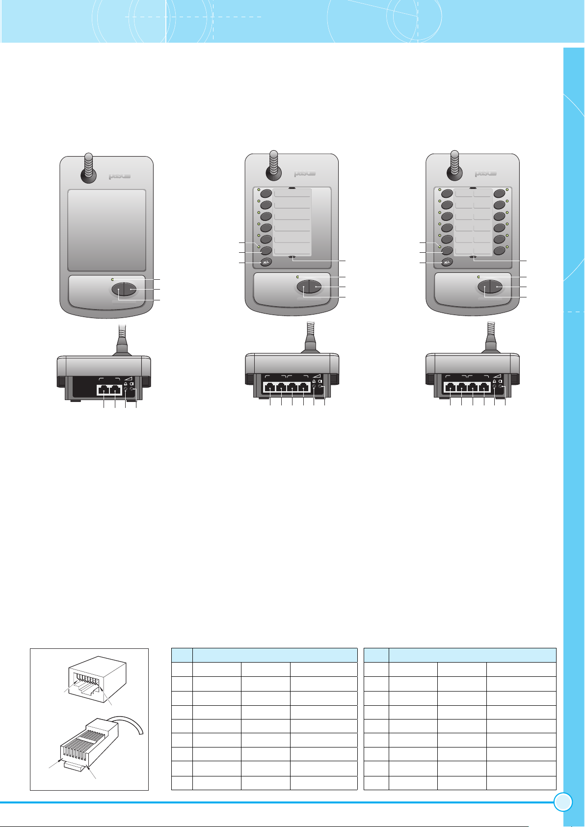
2. De led (3) geeft een reeks knippersignalen
waarmee de op dat moment ingestelde modus
wordt aangegeven.
3.3 Configuración de la modalidad
1. Presionar contemporáneamente las teclas
PTT y LOCK y seguidamente alimentar el
puesto enchufando el cable en la base AUDIO
OUT.
2. El LED (3) emitirá una secuencia de parpadeos
para indicar la modalidad corrientemente
programada:
3.3 Moduseinstellung
1. Drücken Sie gleichzeitig die Tasten PTT und
LOCK und speisen Sie dann die Sprechstelle
ein, indem Sie das Kabel an die Buchse AUDIO
OUT anschließen.
2. Die LED (3) zeigt daraufhin eine Blinksequenz
an, die die zurzeit eingestellte Modalität
angibt.
L= número de parpadeos
3. Die LED (7) geben Hinweis auf die zurzeit
eingestellte Funktion der Tasten:
- Ausgeschaltete LED:Taste für Zonenruf.
- Leuchtende Led: Taste für das Senden des
freigegebenen Alarms.
- Blinkende Led: Taste für das Senden des
deaktivierten Alarms.
4. Für die Änderung des Funktionsmodus der
Sprechstelle drücken Sie die Taste LOCK
einmal oder mehrfach; hiermit wird die Anzahl
der Blinkanzeigen des ausgewählten Modus
angezeigt; im automatischen Modus wird vom
Modus 6 zum Modus 1 gewechselt.
5. Zur Veränderung der Funktion der Zonentasten
drücken Sie die entsprechende Taste, bis Sie
den gewünschten Modus erreichen.
6. Wenn Sie das Menü verlassen wollen, speichern
Sie die Einstellungen und drücken Sie die Taste
PTT; die Sprechstelle ist daraufhin sofort
betriebsbereit.
4. Om de functiemodus van de microfoonplaats
te kunnen wijzigen, moet één of meerdere
keren op de toets LOCK gedrukt worden om
het aantal knippersignalen van de betreffende
led te verkrijgen die gelijk is aan de gekozen
modus; de overgang van modus 6 naar modus
1 is automatisch.
5. Druk voor het wijzigen van de functie van de
zonetoetsen op de gewenste toets, net zolang
totdat de gewenste functie bereikt is.
6. Druk om uit te treden en de instellingen te
bewaren op de toets PTT; de microfoonplaats
is direct klaar voor gebruik.
4. Para modificar la modalidad de funcionamiento
del puesto, presionar la tecla LOCK una o varias
veces para tener el número de parpadeos del
LED correspondiente a la modalidad elegida;
automáticamente se pasará de la modalidad 6
a la modalidad 1.
5. Para modificar la funcionalidad de las teclas de
zona, presionar la tecla de zona deseada hasta
conseguir la funcionalidad deseada.
6. Para salir, guardando las configuraciones,
presionar la tecla PTT; el puesto está
inmediatamente listo para el uso.
3. De leds (7) geven de op dat moment ingestelde
modus aan van de betreffende toetsen:
- Led uit: oproeptoets zone.
- Led aan: toets alarmmelding geactiveerd.
- Led knippert: toets alarmmelding
uitgeschakeld.
3. Los LED (7) indicarán la funcionalidad programada
de las teclas a las cuales se refieren:
- Apagado: tecla de llamada de zona.
- Encendido: tecla de envío alarma habilitada.
- Intermitente: tecla de envío alarma
inhabilitada.
4. GEBRÄUCH
4.1 Allgemeiner Ruf
(B711-G)
Drücken Sie je nach Wunsch den Knopf PTT
oder die Taste LOCK, um den allgemeinen Ruf
zu aktivieren (mit Aktivierung des Chime, falls
eingestellt) und senden Sie die Meldung durch
das Mikrofon: Das Aufleuchten der LED (3)
bestätigt die Aktivierung des Mikrofons. Um den
Vorgang zu beenden, lassen Sie den Knopf PTT
los oder drücken Sie erneut die Taste LOCK:
Die Deaktivierung des Mikrofons wird durch die
Abschaltung der LED bestätigt.
4. GEBRUIK
4.1 Algemene oproep
(B711-G)
Druk naar keuze op de toets PTT of op LOCK
voor het activeren van de algemene oproep (met
activering van de chime, als die is ingesteld) en
het omroepen van een bericht via de microfoon:
de led (3) gaat branden, waarmee de keuze wordt
bevestigd. Laat de knop PTT weer los of druk
opnieuw op de toets LOCK om deze procedure te
beëindigen. Doordat de led ophoudt met branden
wordt bevestigd dat de microfoon uitgeschakeld
is.
4. USO
4.1 Llamada general
(B711-G)
Presionar, como se prefiera, el botón PTT o la
tecla LOCK para activar la llamada general (con
activación del Chime, si programado) y enviar el
mensaje a través del micrófono: el encendido del
LED (3) confirma la activación microfónica. Para
terminar, soltar el botón PTT o presionar de nuevo
la tecla LOCK: la desactivación microfónica quedará
confirmada por el apagado del LED.
- Es können auch die Sprechstellen B711-G
verwendet werden; mit diesen Sprechstellen
können jedoch nur allgemeine Rufe getätigt
werden.
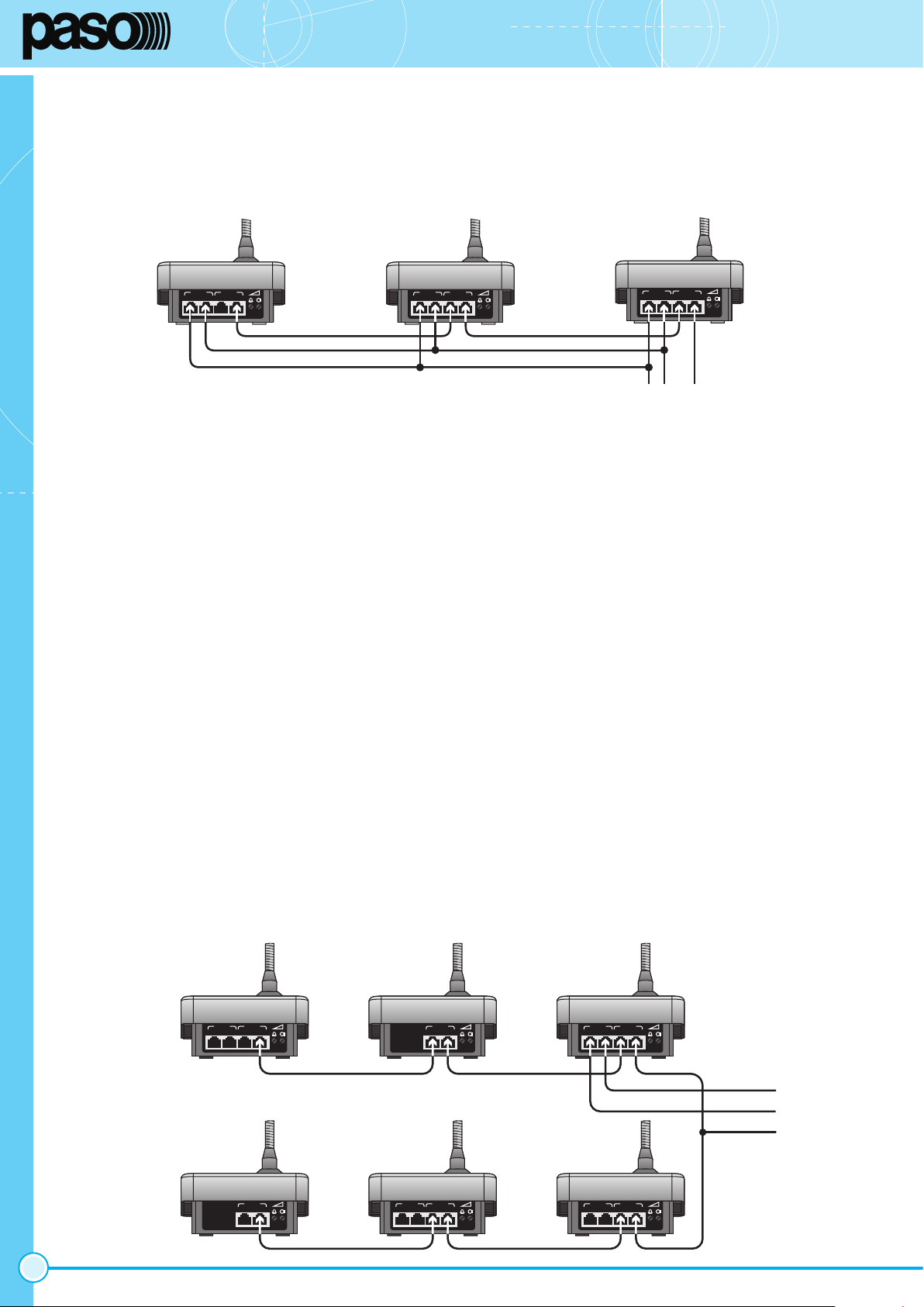
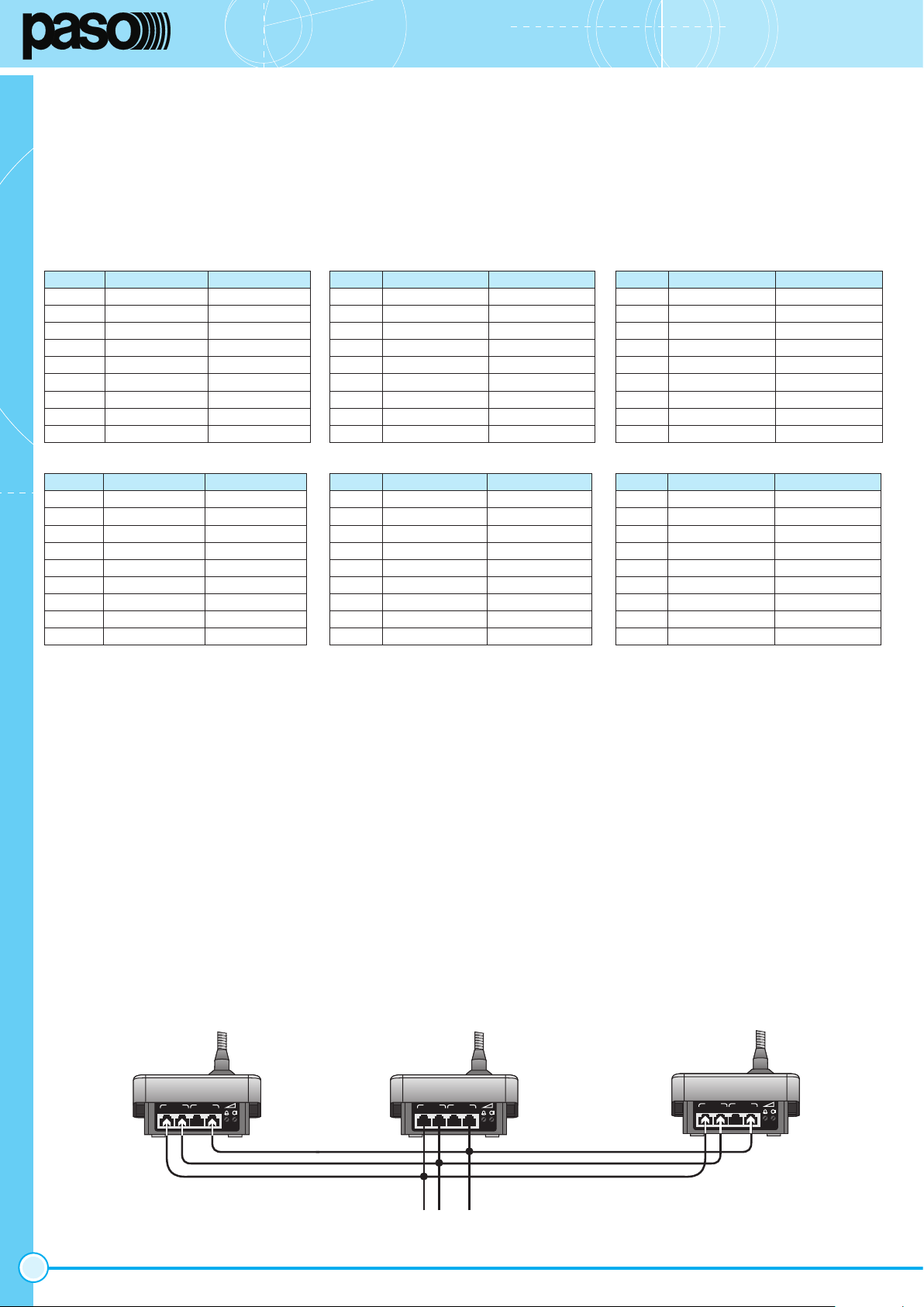
- Die Sprechstellen müssen untereinander per
Kaskadenschaltung (‘daisy-chain’) verbunden
und mit maximal zwei Abzweigleitungen an
das Kontrollgerät angeschlossen werden. Die
Abb.3.2.1 zeigt ein entsprechendes Beispiel.
- het is mogelijk om ook de B711-G microfoon-
plaatsen te gebruiken; deze plaatsen kunnen
alleen algemene oproepen verrichten.
- de microfoonplaatsen moeten in cascade met
elkaar verbonden worden (‘daisy-chain’) waarbij
maximaal twee afgeleide lijnen gebruikt mogen
worden vanaf de besturingsapparatuur. In figuur
3.2.1 staat een toepassingsvoorbeeld.
- Es posible utilizar también los puestos B711-G;
éstos puestos podrán efectuar sólo llamadas
generales.
- Los puestos deben estar conectados en cascada
entre loro (‘daisy-chain’) con un máximo de dos
líneas derivadas a partir del aparato de control.
En la figura 3.2.1, se presenta un ejemplo
aplicativo.
4.2 Zonenruf
(B711/6-G, B711/12-G)
1. Wählen Sie die Zonen durch Drücken der
entsprechenden Tasten auf, um einen Ruf zu
tätigen. Die Led der entsprechenden Zonen
leuchten auf und bestätigen die Auswahl;
drücken Sie die Taste erneut, um eine Zone
auszuschließen; die entsprechende Led wird
ausgeschaltet.
2. Durch Drücken der Taste ALL (allgemeiner
Ruf) werden alle Rufzonen ausgewählt (mit
Ausnahme der Alarmtasten); durch erneutes
Drücken der Taste ALL - bei Auswahl aller Zonen
- werden alle Zonen deaktiviert.
4.2 Oproep van zones
(B711/6-G, B711/12-G)
1. Voor het verrichten van een oproep moeten
de gewenste zones worden geselecteerd met
behulp van de betreffende toetsen: de leds van
de gewenste zones gaan branden ter bevestiging
van de keuze; voor het uitschakelen van een
zone moet opnieuw op de toets worden gedrukt,
waardoor de betreffende led weer dooft.
2. Door op ALL (algemene oproep) te drukken
worden alle op te roepen zones geselecteerd
(met uitsluiting van de alarmtoetsen); door
opnieuw op de toets ALL te drukken, terwijl
alle zones zijn geselecteerd, worden deze weer
uitgeschakeld.
4.2 Llamada de zonas
(B711/6-G, B711/12-G)
1. Para efectuar una llamada, seleccionar las zonas
que se desea presionando las correspondientes
teclas: los LED de las zonas seleccionadas
se encenderán para confirmar la selección;
para deseleccionar una zona presionar de
nuevo la tecla con consiguiente apagado del
correspondiente LED.
2. Presionando la tecla ALL (llamada general) se
seleccionan todas las zonas de llamada (con la
exclusión de las teclas de alarma); presionando
de nuevo la tecla ALL, con todas las zonas
seleccionadas, se tendrá la deselección total.
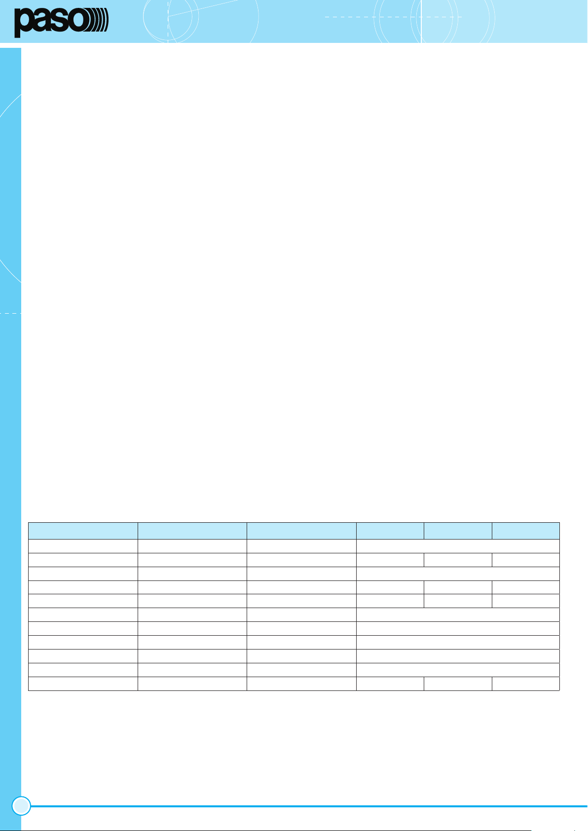
L(*) Modalidad Din-Don
1 Mezcla -
2 Mezcla sí
3 Interbloqueo con baja prioridad -
4 Interbloqueo con baja prioridad sí
5 Interbloqueo con alta prioridad -
6 Interbloqueo con alta prioridad sí
L= aantal knippersignalen
L(*) Modus Ding-Dong
1 Menging -
2 Menging ja
3 Blokkering met lage prioriteit -
4 Blokkering met lage prioriteit ja
5 Blokkering met hoge prioriteit -
6 Blokkering met hoge prioriteit ja
L= Anzahl der Blinksignale
L(*) Modus Ding-Dong
1 Mischung -
2 Mischung ja
3 Interblock mit niedrigem Vorrang -
4 Interblock mit niedrigem Vorrang ja
5 Interblock mit hohem Vorrang -
6 Interblock mit hohem Vorrang ja

B711-G, B711/6-G, B711/12-G
11
3. Die Auswahl der Zonen ist zeitlich begrenzt.
falls die Aktivierung mit den Tasten PTT
oder LOCK nicht innerhalb von circa 5
Sekunde erfolgt, wird die Auswahl annulliert
und die LED der Zonen schalten sich aus.
4. Drücken Sie nach Auswahl der Zonen wie oben
beschrieben je nach Wunsch den Knopf PTT
oder die Taste LOCK, um den allgemeinen
Ruf zu aktivieren (mit Aktivierung des Chime,
falls eingestellt) und senden Sie die Meldung
durch das Mikrofon: Das Aufleuchten der LED
(3) bestätigt die Aktivierung des Mikrofons. Um
den Vorgang zu beenden, lassen Sie den Knopf
PTT los oder drücken Sie erneut die Taste LOCK:
Die Deaktivierung des Mikrofons wird durch die
Abschaltung der LED (3) und der Zonenruf-LED
(7) bestätigt.
MERKE
Durch Drücken der Tasten PTT oder LOCK
ohne eine Zone ausgewählt zu haben, wird eine
allgemeiner Ruf getätigt.
3. De selectie van de zones is een tijdelijk
status: als de activering met behulp van de
toetsen PTT of LOCK niet binnen 5 seconden
nadat de toets voor het laatst is ingedrukt
plaatsvindt, wordt de selectie geannuleerd
en alle zone-leds houden op met branden.
4. Druk na de hier boven beschreven selectie van
de zones naar keuze op de toets PTT of op
LOCK voor het activeren van de oproep (met
activering van de chime, als die is ingesteld) en
het omroepen van een bericht met de microfoon:
de led (3) gaat branden, waarmee de activering
van de microfoon wordt bevestigd. Laat de knop
PTT weer los of druk opnieuw op de toets LOCK
om deze procedure te beëindigen. door het
doven van de led (3) en de leds met betrekking
tot de oproepen naar de zones (7) wordt
bevestigd dat de microfoon uitgeschakeld is.
OPMERKING
Door op de toetsen PTT of LOCK te drukken zonder
dat er eerst zones zijn geselecteerd, wordt een
algemene oproep geactiveerd.
3. La selección de zonas es un estado temporal: si
la activación con las teclas PTT ó LOCK no tiene
lugar dentro de 5 segundos aproximadamente
desde la última presión de tecla, la selección
es anulada y todos los LED de zona se apagan.
4. Efectuada la selección de las zonas tal y
como descrito más arriba, presionar, como
se desee, el botón PTT o la tecla LOCK para
activar la llamada (con activación del Chime, si
programado) y enviar el mensaje a través del
micrófono: el encendido del LED (3) confirma
la activación microfónica. Para terminar,
soltar el botón PTT o presionar de nuevo
la tecla LOCK: la desactivación microfónica
quedará confirmada por el apagado del LED
(3) y de los LED de llamada de zonas (7).
NOTA
Presionando las teclas PTT ó LOCK sin zonas
seleccionadas, se activa una llamada general.
4.3 Aktivierung der Alarme
(B711/6, B711/12)
1. Drücken Sie die als Alarm konfigurierte Taste:
Die entsprechende Led beginnt dann, schnell
zu blinken, um die Bestätigungsaufforderung
anzuzeigen.
2. Drücken Sie innerhalb von 3 Sekunden dieselbe
Taste erneut, um zu bestätigen und um die
Umschaltung zu aktivieren: Die Led zeigt den
Alarmzustand durch ein langsames Blinken an.
Wenn keine Bestätigung erfolgt, wird der Voralarm
annulliert und die Led schaltet sich aus.
3. Drücken Sie erneut die Taste, um die Schaltung
eines Alarms zu deaktivieren. Die entsprechende
Led schaltet sich aus.
4.3 Activering van alarmen
(B711/6, B711/12)
1. Druk op de toets die als alarm geconfigureerd
is: de betreffende led gaat snel knipperen om
het bevestigingsverzoek aan te geven.
2. Druk binnen circa 3 seconden opnieuw op die
zelfde toets ter bevestiging en ter activering
van de omschakeling: de led geeft de
alarmstatus aan door langzaam te knipperen.
Bij het ontbreken van een bevestiging wordt
de vooralarm-status geannuleerd en de led
houdt op met branden.
3. Druk voor het uitschakelen van de omschakeling
van een alarm opnieuw op de toets: ter
bevestiging houdt de led op met branden.
4.3 Aktivierung der Alarme
(B711/6, B711/12)
1. Presionar la tecla configurada como alarma: el
correspondiente LED parpadea rápidamente para
señalar la solicitud de confirmación.
2. Dentro de un tiempo de aproximadamente 3
segundos, presionar de nuevo la misma tecla
para confirmar y activar la conmutación: el LED
señala el estado de alarma con un parpadeo
lento. En caso de falta de confirmación, el estado
de prealarma es anulado y el LED se apaga.
3. Para desactivar la conmutación de una alarma,
presionar de nuevo la tecla: para confirmar, el
LED correspondiente se apaga.
NOTA
La activación de las alarmas no está vinculada a
las llamadas de zonas: de esta manera es posible
tener varias alarmas en curso y efectuar al mismo
tiempo llamadas microfónicas a zonas.
OPMERKING
De activering van de alarmmeldingen staat los van
de oproepen van zones: op deze wijze kunnen
er meerdere alarmmeldingen plaatsvinden en
tegelijkertijd ook microfoonoproepen naar de zones
worden verricht.
MERKE
Die Aktivierung der Alarme ist unabhängig vom
Ruf der Zonen: Auf diese Weise ist es möglich,
mehrere Alarme zu betätigen und gleichzeitig
Mikrofondurchsagen an verschiedene Zonen zu
senden.
TECHNISCHE DATEN TECHNISCHE GEGEVENS DATOS TECNICÓS B711-G B711/6-G B711/12-G
Mikrofontyp Type microfoon Tipo de micrófono elektret / elecret
Anzahl der Zonen Aantal te zones Zonas seleccionables - 6 12
Speisung Voeding Alimentación 12 Vcc / 24 Vcc
Stromaufnahme 12 V-VGS1Absorptie bij 12 Vdc1Absorción de 12 Vcc140 mA 56 mA 72 mA
Stromaufnahme 24 V-VGS1Absorptie bij 24 Vdc1Absorción de 24 Vcc150 mA 62 mA 75 mA
Frequenzgang Frequentiebereik Respuesta en frequencia 100 ÷ 15.000 Hz
Audiostufe (symmetriert) Geluidsniveau (gebalanceerd) Nivel de sonido (balanceado) 1,2 Vrms*
Stufe Ding-Dong Ding-Dong niveau Nivel din-don 0,8 Vpp*
Dynamikbegrenzer Dynamiekbegrenzer Limitador de dinámica ja / sí
Abmessungen Afmetingen Dimensiones 116 x 60 (416) x 200 mm
Gewicht Gewicht Peso 0,82 kg 0,85 kg 0,87 kg
*
einstellbar, regelbaar, regulable.
1
ohne Absorption Relaisschaltpunkte Zonen / uitzondering absorptie relaisschakelpunten zones / con exclusión de las zonas de relevo de absorción de conmutación.

Questo prodotto è conforme alle Direttive della Comunità Europea
sotto le quali lo stesso ricade. This product is in keeping with the relevant European Community
Directives.
Advertencias para la eliminación correcta del producto según establece la
Directiva Europea 2002/96/EC Al final de su vida útil, el producto no debe eliminarse
junto a los residuos urbanos. Debe entregarse a centros específicos de recogida
selectiva establecidos por las administraciones municipales, o a los revendedores
que facilitan este servicio. Eliminar por separado un aparato eléctrico o electrónico
(RAEE) significa evitar posibles consecuencias negativas para el medio ambiente y
la salud derivadas de una eliminación inadecuada y permite reciclar los materiales
que lo componen, obteniendo así un ahorro importante de energía y recursos. Para
subrayar la obligación de eliminar por separado el aparato, en el producto aparece un
contenedor de basura móvil listado.
Garantía Este producto está garantizado libre de defectos en sus materias primas
y en su montaje; el periodo de garantía se rige por las normas vigentes. La Paso
reparará gratuitamente el producto defectuoso aquí garantizado si el defecto
resultará haberse presentado durante el uso normal; la garantía no ampara pues
los productos utilizados e instalados de manera errónea, dañados mecánicamente,
dañados por líquidos o por agentes atmosféricos. El producto, que haya resultado
defectuoso, deberá ser enviado a la Paso con portes pagados de envío y de vuelta.
Esta garantía no incluye otras, explícitas o implícitas, y no incluye daños o accidentes
consiguientes a personas o cosas. Contactar con los distribuidores PASO de la zona
para más información acerca de la garantía.
Nota La PASO S.p.A rehusa cualquier responsabilidad ante daños a cosas y/o personas causados por una utilización no correcta del aparato o por operaciones no conformes a
cuanto indicado en este folleto. Siempre con la firme intención de mejorar sus productos, Paso S.p.A. se reserva el derecho de modificar los dibujos y las características técnicas,
sin preaviso alguno.
Belangrijke informatie voor de verwerking van het product in overeenstemming
met de Europese Richtlijn 2002/96/EC Aan het einde van zijn levensduur mag
het product niet samen met het gewone huishoudelijke afval worden verwerkt. Het moet
naar het daartoe bestemde gemeentelijke verzamelpunt voor gescheiden afval worden
gebracht, of naar een verkooppunt dat deze service verleent. Het apart verwerken van
afgedankte elektrische en elektronische apparatuur (AEEA) voorkomt mogelijk negatieve
gevolgen voor het milieu en de gezondheid die door een ongeschikte verwerking ontstaan
en zorgt ervoor dat de materialen waaruit het apparaat is samengesteld teruggewonnen
kunnen worden om een aanmerkelijke besparing van energie en grondstoffen te
verkrijgen. Om op de verplichting tot gescheiden verwerking van elektrische apparatuur te
wijzen, is op het product het symbool van een doorgekruiste vuilnisbak aangebracht.
Garantie Dit product is gegarandeerd vrij van materiaal- en constructiefouten; de
garantieduur wordt geregeld door de geldende wettelijke voorschriften. Paso voert
de reparatie van de hier gegarandeerde defecte producten kosteloos uit, indien
blijkt dat het defect tijdens normaal gebruik is opgetreden. De garantie heeft dus
geen betrekking op verkeerd gebruikte of geïnstalleerde producten, producten die
mechanisch beschadigd zijn of beschadigingen hebben opgelopen door vloeistoffen of
de invloed van weersomstandigheden. Producten waarbij een defect is geconstateerd
dienen franco verzend- en retourkosten aan Paso opgestuurd te worden. Deze garantie
omvat geen enkele andere expliciete of impliciete garantie en dekt geen schade aan
personen of zaken. Voor verdere informatie over de garantie dient contact opgenomen
te worden met de dichtstbijzijnde PASO distributeur.
Opmerking PASO S.p.A kan niet aansprakelijk worden gesteld voor schade aan voorwerpen en/of persoonlijk letsel die het gevolg zijn van een onjuist gebruik van het apparaat
of van procedures die niet overeenkomen met de voorschriften uit deze handleiding. Aangezien PASO S.p.A. voortdurend verbeteringen aanbrengt aan haar producten, behoudt
zij zich het recht voor op ieder moment zonder voorbericht de tekeningen en technische eigenschappen aan wijzigen te onderwerpen.
Wichtiger Hinweis für die Entsorgung des produkts in übereinstimmung
mit der EG-richtlinie 2002/96/EC Am Ende seiner Nutzzeit darf das Produkt
nicht zusammen mit dem Siedlungsabfall beseitigt werden, sondern es muss bei den zu
diesem Zweck von den städtischen Behörden eingerichteten Sammelstellen oder zu den
Fachhändlern, die einen Rücknahmeservice anbieten, gebracht werden. Die getrennte
Entsorgung von Elektro- und Elektronik-Altgeräten (WEEE - Waste Electric and Electronic
Equipment) vermeidet mögliche negative Auswirkungen auf die Umwelt und die Gesundheit
infolge einer nicht vorschriftsmäßigen Entsorgung. Zudem wird die Wiederverwertung der
Materialen, aus denen das Gerät besteht, ermöglicht, so dass eine bedeutende Einsparung
an Energie und Ressourcen erzielt wird. Aus diesem Grund ist das Produkt mit dem Symbol
einer durchgestrichenen Mülltonne gekennzeichnet.
Garantie Für dieses Produkt wird eine Garantie für Rohmaterialfehler und Montagefehler
gewährt; die Garantiezeit unterliegt den gültigen gesetzlichen Bestimmungen. Paso
repariert das garantierte Produkt kostenlos, wenn sich herausstellt, dass der Defekt
während des normalen Gebrauchs aufgetreten ist; die Garantie erstreckt sich demnach
nicht auf Produkte, die falsch gebraucht und installiert oder mechanisch, durch
Flüssigkeiten oder Umwelteinflüsse beschädigt wurden. Das defekte Produkt muss
franco Versandkosten für den Hin- und Rücktransport zu und von Paso gesendet
werden. Diese Garantie schließt keine weiteren, expliziten oder impliziten Leistungen
und Folgeschäden an Personen, Gegenständen oder Unfälle ein. Bitte wenden Sie
sich an PASO-Fachhandel in Ihrer Gegend, wenn Sie weitere Informationen zu dieser
Garantie wünschen.
Merke PASO S.p.A lehnt jede Haftung für Schäden an Personen und / oder Gegenständen ab, die durch unzweckmäßige Verwendung oder Vorgehen entstehen, die nicht den
Anweisungen dieses Handbuches entsprechen. In der Überzeugung, die eigenen Produkte beständig verbessern zu wollen, behält sich PASO S.p.A. das Recht vor, jederzeit und
ohne Vorankündigung Änderungen an technischen Zeichnungen und - Merkmalen vorzunehmem.
Recommandations pour l’élimination du produit conformément à la
Directive Européenne 2002/96/EC Au terme de son utilisation, le produit ne doit
pas être éliminé avec les déchets urbains. L’appareil doit être remis à l’un des centres
de tri sélectif agréés par l’administration communale ou à un revendeur assurant ce
service. L’élimination différenciée des appareils électroniques (DEEE) permet non
seulement d’éviter les retombées négatives pour l’environnement et la santé dues à
une élimination incorrecte, mais aussi de récupérer les matériaux qui le composent et
permet ainsi d’effectuer d’importantes économies en termes d’énergie et de ressources.
Pour rappeler l’obligation d’éliminer séparément les appareils électroniques, le produit
porte le symbole d’un caisson à ordures barré.
Garantie Ce produit est garanti comme étant exempt de défauts de matières premières
et de fabrication. La durée de la garantie est conforme aux normes en vigueur. Paso
réparera gratuitement tout produit défectueux en garantie dès lors que l’anomalie se
vérifiera dans le cadre d’une utilisation normale du produit. La garantie ne couvre donc
pas les produits utilisés et installés de façon erronée, endommagés mécaniquement ou
encore souillés par des liquides ou des agents atmosphériques. Le produit défectueux
devra être envoyé à Paso franco de frais d’expédition et de réexpédition. La présente
garantie n’en inclut aucune autre, explicite ou implicite, et ne couvre pas les lésions
ou dommages causés aux personnes ou aux choses. Pour plus d’informations sur la
garantie, veuillez contacter le distributeur PASO de votre zone.
Note PASO S.p.A décline toute responsabilité en cas de dommages matériels et/ou physiques provoqués par l’utilisation impropre de l’appareil ou encore par des opérations
ou des interventions ne respectant pas les instructions figurant dans la présente notice. En raison de l’amélioration constante de ses produits, PASO S.p.A. se réserve le droit
d’apporter des modifications aux dessins et caractéristiques techniques à tout instant et sans préavis aucun.
Important information for correct disposal of the product in accordance
with EC Directive 2002/96/EC This product must not be disposed of as urban
waste at the end of its working life. It must be taken to a special waste collection
centre licensed by the local authorities or to a dealer providing this service. Separate
disposal of electric and/or electronic equipment (WEEE) will avoid possible negative
consequences for the environment and for health resulting from inappropriate disposal,
and will enable the constituent materials to be recovered, with significant savings in
energy and resources. As a reminder of the need to dispose of this equipment separately,
the product is marked with a crossed-out wheeled dustbin.
Warranty This product is warranted to be free from defects in raw materials and
assembly. The warranty period is governed by the applicable provisions of law. Paso
will repair the product covered by this warranty free of charge if it is faulty, provided
the defect has occurred during normal use. The warranty does not cover products that
are improperly used or installed, mechanically damaged or damaged by liquids or the
weather. If the product is found to be faulty, it must be sent to Paso free of charges
for shipment and return. This warranty does not include any others, either explicit or
implicit, and does not cover consequential damage to property or personal injury. For
further information concerning the warranty contact your local PASO distributor.
Note PASO S.p.A will not accept any liability for damage to property and/or persons arising out of incorrect use of the equipment or of procedures that do not comply with the
instructions provided in this booklet. PASO S.p.A. strive to improve their products continuously, and therefore reserve the right to make changes to the drawings and technical
specifications at any time and without notice.
Avvertenze per lo smaltimento del prodotto ai sensi della Direttiva Europea
2002/96/EC Alla fine della sua vita utile il prodotto non deve essere smaltito insieme
ai rifiuti urbani, ma deve essere consegnato presso gli appositi centri di
raccolta differenziata predisposti dalle amministrazioni comunali, oppure
presso i rivenditori che forniscono questo servizio. Smaltire separatamente
un rifiuto elettrico e/o elettronico (RAEE) consente di evitare possibili
conseguenze negative per l’ambiente e per la salute derivanti da un suo
smaltimento inadeguato e permette di recuperare i materiali di cui è
composto al fine di ottenere un importante risparmio di energia e di risorse.
Su ciascun prodotto è riportato a questo scopo il marchio del contenitore
di spazzatura barrato.
Garanzia Questo prodotto è garantito esente da difetti nelle sue materie prime e nel
suo montaggio; il periodo di garanzia è regolamentato dalle norme vigenti. La Paso
riparerà gratuitamente il prodotto difettoso qui garantito se il difetto risulterà essersi
verificato durante l’uso normale; la garanzia non si estende quindi a prodotti usati ed
installati in modo errato, danneggiati meccanicamente, danneggiati da liquidi o da
agenti atmosferici. Il prodotto, risultato difettoso, dovrà essere inviato alla Paso franco
di spese di spedizione e ritorno. Questa garanzia non ne comprende altre, esplicite od
implicite, e non comprende danni o incidenti conseguenti a persone o cose. Contattare
i distributori PASO della zona per maggiori informazioni sulla garanzia.
Nota La PASO S.p.A declina ogni responsabilità per danni a cose e/o persone derivanti dall’uso non corretto dell’apparecchio o da procedure non rispondenti a quanto riportato
sul presente libretto. Nel continuo intento di migliorare i propri prodotti, la PASO S.p.A. si riserva il diritto di apportare modifiche ai disegni e alle caratteristiche tecniche in
qualsiasi momento e senza alcun preavviso.
PASO S.p.A Via Settembrini, 34 - 20020 Lainate (MI) - ITALIA • TEL. +39-02580771 • FAX +39-0258077277 • www.paso.it • Printed in Italy • Ed. 09/09 • 11/636-B
This manual suits for next models
2
Table of contents
Other Paso Microphone manuals
Popular Microphone manuals by other brands

Widex
Widex COM-DEX User instructions

Electro-Voice
Electro-Voice N50 Specfications

Konig & Meyer
Konig & Meyer 23560 quick start guide

PCB Piezotronics
PCB Piezotronics 377A53 Installation and operating manual

Beyerdynamic
Beyerdynamic TG I53c Product information

Beyerdynamic
Beyerdynamic TG D35d Product information