Shock Mount
Internal rubber vibration isolator
Cable
Highly durable cable with effective hum shielding, four con-
ductors (two shielded), plastic jacketed
Model 515SBGX: 1.8 m (70 in.)
Models 515SBG-18X and 515SBG-18XF: 1.3 m (51 in.) from
gooseneck
Case
Silver finish die casting with black enamel diecast grille and
stainless steel screen
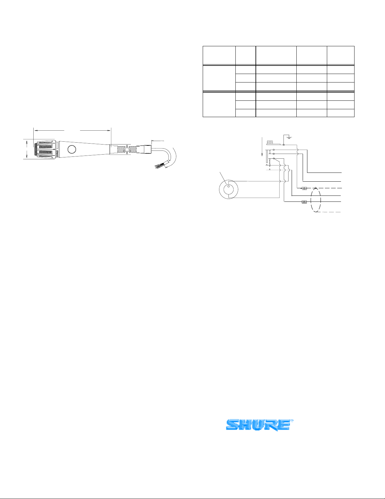
Dimensions
See Figure 3
51 in.
120 cm
1.5 in.
3.75 cm
6.5 in.
16.5 cm
0.85 in.
2 cm
OVERALL DIMENSIONS
FIGURE 3
Certification
Conforms to European Union directives, eligible to bear CE
marking; meets European Union EMC Immunity Require-
ments (EN 55103).
Net Weight
515SBGX 380 g (13.5 oz). . . . . . . . . . . . . . . . . . . . . . . . . . .
515SBG-18X 900 g (31.8 oz). . . . . . . . . . . . . . . . . . . . . . . .
515SBG-18XF 787 g (27.8 oz). . . . . . . . . . . . . . . . . . . . . . .
FURNISHED ACCESSORIES
1.27 mm (.050 in.) Hex Wrench 80A67. . . . . . . . . . . . . . . . .
45.75 cm (18 in.)Gooseneck
(515SBG-18X, 515SBG-18XF only) G18. . . . . . . . . . . . .
Flange (515SBG-18X only) A13HD. . . . . . . . . . . . . . . . . . .
Flange (515SBG-18XF only) A12. . . . . . . . . . . . . . . . . . . . .
REPLACEMENT PARTS
Cartridge R180. . . . . . . . . . . . . . . . . . . . . . . . . . . . . . . . . . . . .
Grille Assembly RK334G. . . . . . . . . . . . . . . . . . . . . . . . . . . .
Cable 70A4063. . . . . . . . . . . . . . . . . . . . . . . . . . . . . . . . . . . .
Gooseneck (515SBG-18X, 515SBG-18XF) G18. . . . . . . . .
Flange (515SBG-18X) A13HD. . . . . . . . . . . . . . . . . . . . . . . .
Flange(515SBG-18XF) A12. . . . . . . . . . . . . . . . . . . . . . . . . .
Windscreen A85WS. . . . . . . . . . . . . . . . . . . . . . . . . . . . . . . . .
CONNECTIONS
These low-impedance microphones are designed for con-
nection to microphone inputs rated at 75 to 300 ohms. Using ba-
lanced-line low-impedance cables permits very long cable
lengths without affecting response or level. The RED and
BLACK cable leads are the microphone conductors for ba-
lanced-line connections; the shield is connected to the amplifier
ground.
For unbalanced operation, connect the BLACK lead to the
shield, and use the RED lead as the microphone conductor.
The GREEN and WHITE cable leads are used to control an
external relay or control circuit. Refer to the following table and
to the wiring diagram in Figure 4.
INPUT TYPE WIRE
COLOR FUNCTION XLR
CONNECTOR 1/4 IN.
PHONE
PLUG
RED AUDIO PIN 2 TIP
UNBALANCED BLACK AUDIO GROUND PIN 3 SLEEVE
SHIELD CHASSIS GROUND PIN 1 SLEEVE
RED AUDIO + PIN 2 TIP
BALANCED BLACK AUDIO –PIN 3 RING
SHIELD CHASSIS GROUND PIN 1 SLEEVE
SHIELD
RED
BLACK
BLUE
GREEN
WHITE
DIRECTION TO ACTUATE
SWITCH CASE GROUND
CARTRIDGE
RED DOT
INTERNAL CONNECTIONS
FIGURE 4
MOUNTING THE 515SBG-18X AND 515SBG-18XF
Mount the 515SBG-18X or 515SBG-18XF as follows:
1. Thread the supplied hexnut all the way down on the mount-
ing flange.
2. Thread the gooseneck tightly on the flange.
3. Back the hexnut up against the gooseneck, and use a
wrench to tighten the nut firmly against the bottom of the
gooseneck.
MOUNTING THE 515SBX ONTO A GOOSENECK
Mount the 515SBGX onto a gooseneck or fixed pipe with a
5/8in–27 thread as follows:
1. Unscrew the black end cap from the microphone.
2. Remove the thin metal washer and the metal spacer.
3. Re-install the washer by sliding it back onto the cable and up
into the end of the microphone.
4. Slip the cable into the gooseneck or pipe and thread the mi-
crophone firmly to the mount.
For additional service or parts information, please contact
Shure’s Service department at 1–800–516–2525. Outside the
United States, please contact your authorized Shure Service
Center.
SHURE Incorporated Web Address: http://www.shure.com
5800 W. Touhy Avenue, Niles, IL 60714-4608, U.S.A.
Phone: 800-257-4873 Fax: 847-866-2279
In Europe, Phone: 49-7131-72140 Fax: 49-7131-721414
In Asia, Phone: 852-2893-4290 Fax: 852-2893-4055
Elsewhere, Phone: 847-866-2200 Fax: 847-866-2585


