Paso 8000 Seris User manual

SERIE 8000 1
Preamplificatore-miscelatore
Preamplifier-mixer
Preamplificateur-mixeur
MX8033
MX8033/117
8000
SERIE
SERIES
ISTRUZIONI PER LUSO INSTRUCTIONS FOR USE MANUEL DUTILISATION
SOMMARIO
1. Descrizione generale
1.1 Introduzione........................................ 3
1.2 Pannello frontale ................................. 3
1.3 Pannello posteriore .............................. 3
2. Avvertenze generali
2.1 Installazione ........................................ 4
2.2 Alimentazione e messa a terra ............. 4
2.3 Note di sicurezza ................................. 4
3. Connessioni
3.1 Criteri generali .................................... 5
3.2 Ingressi microfonici .............................. 5
3.3 Ingressi ausiliari ................................... 5
3.4 Uscita per registratore ......................... 6
3.5 Ingresso base-amplificata .................... 6
3.6 Uscita miscelata ................................... 6
3.7 Ingresso/uscita di espansione .............. 6
3.8 Morsettiera di precedenza ................... 6
3.9 Controlli aggiuntivi ............................... 6
4. Uso dellapparecchio
4.1 Accensione .......................................... 7
4.2 Selezione e controllo
degli ingressi ........................................ 7
4.3 Controllo di volume principale ............... 7
4.4 Precedenza base amplificata................ 7
4.5 Precedenza automatica ....................... 7
4.6 Precedenza microfonica ....................... 7
5. Note di servizio
5.1 Avvertenze ......................................... 8
5.2 Sostituzione del fusibile di rete ............ 8
5.3 Sostituzione del fusibile interno ........... 8
5.4 Installazione dei
trasformatori microfonici ...................... 8
5.5 Moduli aggiuntivi .................................. 8
6. Caratteristiche tecniche............... 9
7. Lista delle parti di ricambio ........ 10
TABLE OF CONTENTS
1. General description
1.1 Introduction ........................................ 3
1.2 Front panel ......................................... 3
1.3 Rear panel .......................................... 3
2. General warnings
2.1 Installation .......................................... 4
2.2 Power supply and earthing .................. 4
2.3 Safety notes ....................................... 4
3. Connections
3.1 General features ................................. 5
3.2 Microphone inputs ............................... 5
3.3 Auxiliary inputs.................................... 5
3.4 Tape output......................................... 6
3.5 Amplified base input ............................ 6
3.6 Mixed output ....................................... 6
3.7 Expansion input/output ....................... 6
3.8 Precedence terminal strip .................... 6
3.9 Additional controls ............................... 6
4. Operation
4.1 Power up ............................................. 7
4.2 Inputs selection
and control .......................................... 7
4.3 Master volume control ......................... 7
4.4 Amplified base precedence .................. 7
4.5 Automatic precedence ......................... 7
4.6 Microphone precedence ....................... 7
5. Service notes
5.1 Warnings............................................. 8
5.2 Replacements of the mains fuse .......... 8
5.3 Replacements of the internal fuse ....... 8
5.4 Microphone transformers
installation ........................................... 8
5.5 Additional modules............................... 8
6. Technical specifications ............... 9
7. List of spare parts ....................... 10
SOMMAIRE
1. Description générale
1.1 Introduction ...................................... 11
1.2 Panneau avant .................................. 11
1.3 Panneau arriêre ................................ 11
2. Precautions générales
2.1 Installation ........................................ 12
2.2 Alimentation et mise à la terre ........... 12
2.3 Conseils de securité ........................... 12
3. Connexions
3.1 Criteres generaux ............................. 13
3.2 Entrées microphoniques ..................... 13
3.3 Entrées auxiliaires ............................. 13
3.4 Sortie pour enregistreur .................... 14
3.5 Entrée base amplifiée ........................ 14
3.6 Sortie mixée ...................................... 14
3.7 Entrée/sortie d'extension .................. 14
3.8 Bornier de priorité ............................. 14
3.9 Controles supplementaires ................ 14
4. Utilisation de l'appareil
4.1 Mise en marche .................................. 15
4.2 Selection et contrôle
des entrées ....................................... 15
4.3 Contrôle de volume general ............... 15
4.4 Priorité base amplifiée ........................ 15
4.5 Priorité automatique .......................... 15
4.6 Priorité micro ..................................... 15
5. Notices de service
5.1 Precautions ....................................... 16
5.2 Substitution du fusible d'alimentation .... 16
5.3 Substitution du fusible interne ........... 16
5.4 Installation des
transformateur micro ......................... 16
5.5 Modules supplementaires ................... 16
6. Caractéristiques techniques ...... 17
7. Liste des pieces detachées ........ 18
11-536.p65 03/12/01, 10.281

SERIE 8000
2
8000
SERIE
SERIES
Vorverstärker-mixer
Voorversterker-mixer
Preamplificador-mezclador
MX8033
MX8033/117
GEBRUIKSAANWIJZING INSTRUCCIONES DE EMPLEOGEBRAUCHSANLEITUNG
INHALTSANGABE
1. Allgemeine Beschreibung
1.1 Einleitung .......................................... 11
1.2 Frontplatte ........................................ 11
1.3 Rückpaneel ....................................... 11
2. Allgemeine hinweise
2.1 Installation ........................................ 12
2.2 Einspeisung und erdung ..................... 12
2.3 Sicherheitsanweisungen .................... 12
3. Anschlüsse
3.1 Allgemeine hinweise ........................... 13
3.2 Mikrofoneingänge .............................. 13
3.3 Hilfseingänge ..................................... 13
3.4 Ausgang für das Aufnahmegerät ....... 14
3.5 Eingang verstärkte Sprechstelle......... 14
3.6 Mischausgang .................................... 14
3.7 Erweiterungseingang/-Ausgang ......... 14
3.8 Klemmenbrett für die Vorrangschaltung 14
3.9 Zusätzliche Kontrolleinheiten.............. 14
4. Gebrauch des geräts
4.1 Einschalten ........................................ 15
4.2 Auswahl und Regulierung
der Eingänge ..................................... 15
4.3 Hauptlautstärkeregler........................ 15
4.4 Vorrangschaltung der
Verstärken Sprechstelle ..................... 15
4.5 Automatischer Vorrang ...................... 15
4.6 Mikrofonvorrang ................................ 15
5. Serviceanweisungen
5.1 Besondere Hinweise .......................... 16
5.2 Ausweschseln der Netzsicherung ....... 16
5.3 Ausweschseln der internen Sicherung 16
5.4 Installation der
Mikrofontransformatoren ................... 16
5.5 Zusätzliche Module ............................ 16
6. Technische Eigenschaften .......... 17
7. Ersatzeilliste ................................ 18
INHOUD
1. Algemene beschrijving
1.1 Inleiding ............................................ 19
1.2 Voorpaneel ........................................ 19
1.3 Achterpaneel..................................... 19
2. Algemene waarschuwingen
2.1 Installatie .......................................... 20
2.2 Stroomvoorziening en aarding ........... 20
2.3 Opmerkingen over de veiligheid ......... 20
3. Verbindingen
3.1 Algemene criteria .............................. 21
3.2 Microfooningangen ............................ 21
3.3 Hulpingangen .................................... 21
3.4 Uitgang voor opname-apparaat ......... 22
3.5 Versterkte basisingang ....................... 22
3.6 Gemixte uitgang ................................ 22
3.7 Expansie-in/uitgang ........................... 22
3.8 Voorrangsklemmenbord ...................... 22
3.9 Extragelingen .................................... 22
4. Gebruik van het apparaat
4.1 Aanzetten ......................................... 23
4.2 Ingangkeuze
en regeling ........................................ 23
4.3 Hoofdvolumeregeling ......................... 23
4.4 Versterkte
basisvoorrang ................................... 23
4.5 Automatische voorrang ..................... 23
4.6 Microfoonvoorrang ............................ 23
5. Dienstopmerkingen
5.1 Waarschuwingen ............................... 24
5.2 Netzekeringen vervangen .................. 24
5.3 Interne zekering vervangen .............. 24
5.4 Installatie
Microfoontransformatoren................. 24
5.5 Extra modulen ................................... 24
6. Technische kenmerken .............. 25
7. Lijst van onderdelen ................... 26
SUMARIO
1. Descripción general
1.1 Introducción ...................................... 19
1.2 Panel delantero ................................. 19
1.3 Panel trasero ..................................... 19
2. Advertencias generales
2.1 Instalación ........................................ 20
2.2 Alimentación y puesta a tierra ........... 20
2.3 Notas sobre la seguridad ................... 20
3. Conexiones
3.1 Criterios generales ............................ 21
3.2 Entradas microfónicas........................ 21
3.3 Entradas auxiliares ............................ 21
3.4 Salida para grabadora ....................... 22
3.5 Entrada base amplificada................... 22
3.6 Salida mezclada ................................. 22
3.7 Entrada/salida de expansión.............. 22
3.8 Regleta de precedencia ..................... 22
3.9 Controles adicionales ......................... 22
4. Uso del aparato
4.1 Encendido ......................................... 23
4.2 Seleccion y control
de las entradas ................................. 23
4.3 Control de volumen principal .............. 23
4.4 Precedencia
base amplificada ................................ 23
4.5 Precedencia automatica ..................... 23
4.6 Precedencia microfónica .................... 23
5. Notas de servicio
5.1 Advertencias ..................................... 24
5.2 Substitucion del fusible de red ........... 24
5.3 Substitucion del fusible interior .......... 24
5.4 Instalación de los
transformadores microfónicos ............ 24
5.5 Modulos adicionales ........................... 24
6. Datos tecnicos ............................. 25
7. Partes de recambio ..................... 26
11-536.p65 03/12/01, 10.282

SERIE 8000 3
GENERAL DESCRIPTION1DESCRIZIONE GENERALE
1.2 PANNELLO FRONTALE
[1] Controlli di livello degli ingressi microfonici.
[2] Filtri SPEECH CORRECTOR.
[3] Controllo di livello degli ingressi ausiliari.
[4] Selettore degli ingressi ausiliari.
[5] Controllo di volume generale.
[6] Interruttore di rete.
[7] Spia daccensione.
1.3 PANNELLO POSTERIORE
[8] Connessione di massa telaio.
[9] Morsettiera per alimentazione esterna in corrente continua.
[10] Controlli dei moduli aggiuntivi.
[11] Morsettiere per la precedenza microfonica.
[12] Selettore per esclusione alimentazione phantom su MIC.1 e MIC.2.
[13] Ingressi microfonici.
[14] Controllo di livello dell'ingresso LINE.
[15] Ingressi ausiliari.
[16] Uscita per registratore.
[17] Controllo di livello dell'ingresso BASE.
[18] Controllo del livello di soglia della precedenza automatica.
[19] Ingresso base microfonica amplificata.
[20] Uscita del segnale miscelato.
[21] Uscita per estensione.
[22] Ingresso per estensione.
[23] Spina di rete con fusibile incorporato.
1.1 INTRODUZIONE
Il preamplificatore-miscelatore PASO MX8033 (MX8033/117) è un
apparecchio con caratteristiche tecniche avanzate di grande versatilità e
semplicità duso, adatto ad una vasta gamma di applicazioni professionali.
Le principali caratteristiche tecniche e funzionali possono essere così
riassunte:
sei ingressi microfonici bilanciati elettronicamente - possibilità di
bilanciamento con trasformatore (opzionale) su due di questi ingressi.
quattro ingressi ausiliari selezionabili di cui uno con controllo di sensibilità.
uscita bilanciata ad alto livello.
uscita ausiliaria per registratore.
ingresso e uscita del bus di miscelazione per estensione ingressi.
ingresso base amplificata con precedenza automatica.
filtro SPEECH CORRECTOR attivabile su tutti gli ingressi microfonici.
alimentazione phantom per microfoni a condensatore.
precedenza microfonica a più livelli.
predisposizione per moduli interni aggiuntivi.
Per ottenere i massimi vantaggi dalluso dellapparecchio si raccomanda
unattenta lettura delle istruzioni che seguono.
1.1 INTRODUCTION
The PASO MX8033 (MX8033/117) preamplifier-mixer is an extremely
versatile and easy to use device with avant-garde technical
characteristics, ideal for a wide range of professional applications.
The main technical and functional characteristics may be summarized as
follows:
six electronically balanced microphone inputs - possibility of balancing
with a transformer (optional) on two of these inputs.
four selectable auxiliary inputs of which one has a sensitivity control.
high-level balanced output.
auxiliary tape output.
input/output of mixer bus for inputs expansion.
amplified base input with automatic precedence.
SPEECH CORRECTOR filter which may be activated on all microphone inputs.
phantom power supply for capacitor microphones.
multi-level microphone precedence.
designed for additional internal modules.
To make the most of the advantages offered by the use of the device, we
recommend you read the instructions provided below carefully.
1.2 FRONT PANEL
[1] Microphone input level controls.
[2]
SPEECH CORRECTOR filters.
[3] Auxiliary input level control.
[4] Auxiliary input selector switch.
[5] Master volume control.
[6] Mains switch.
[7] POWER ON indicator lamp.
1.3 REAR PANEL
[8] Chassis ground connection.
[9] Terminal strip for external direct current power supply.
[10] Addictional modules controls.
[11] Terminal strips for microphone precedence.
[12] Selector switches for MIC.1 and MIC.2 phantom supply exclusion.
[13] Microphone inputs.
[14] LINE input level control.
[15] Auxiliary inputs.
[16] Recorder output.
[17] BASE input level control.
[18] Automatic precedence threshold level control.
[19] Amplified base input.
[20] Mixed signal output.
[21] Mixer extension output.
[22] Mixer extension input.
[23] Mains plug with built-in fuse.
11-536.p65 03/12/01, 10.283

SERIE 8000
4
GENERAL WARNINGS2AVVERTENZE GENERALI
2.1 INSTALLAZIONE
Tutti gli apparecchi PASO sono costruiti nel rispetto delle più severe
normative internazionali di sicurezza ed in ottemperanza ai requisiti
della Comunità Europea. Per un corretto ed efficace uso dellapparecchio
è importante prendere conoscenza di tutte le caratteristiche leggendo
attentamente le presenti istruzioni ed in particolare le note di sicurezza.
Durante il funzionamento dellapparecchio è necessario assicurare
unadeguata ventilazione. Evitare di racchiudere lapparecchio in un
mobile privo di aerazione o di ostruire le fessure di ventilazione
appoggiando oggetti od accessori sulla parte superiore. Evitare inoltre
di tenere lapparecchio in prossimità di sorgenti di calore.
Il mixer è predisposto per il montaggio in rack 19; per questo tipo
dinstallazione occorre innanzitutto rimuovere i quattro piedini dal fondo,
fissare quindi lapparecchio al rack utilizzando le viti e le rondelle fornite
a corredo. Prima dellaccensione assicurarsi che tutti gli ingressi e le
uscite siano correttamente collegati.
2.2 ALIMENTAZIONE E MESSA A TERRA
Lapparecchio è predisposto per il funzionamento con tensione di rete
a 230 V ± 10% 50/60 Hz (117 V ± 10% 50/60 Hz per la versione
MX8033/117). E prevista, in alternativa, la possibilità di alimentare
lapparecchio con una tensione continua esterna di +24V.
Tipicamente questa tensione, che deve essere applicata rispettando le
polarità ai relativi terminali della morsettiera [9], proviene da accumulatori
mantenuti sotto carica in tampone ed entra in funzione soltanto in caso
di emergenza; è necessario, in questo caso, prevedere luso di un relè
esterno che connetta le batterie allapparecchio solo quando viene a
mancare lalimentazione di rete.
In accordo con le normative di sicurezza, linterruttore di accensione [6]
agisce solo sulla tensione di rete.
Lapparecchio è protetto da fusibili per entrambi i tipi di alimentazione:
consultare la sezione 5 NOTE DI SERVIZIO per la loro eventuale
sostituzione. Lapparecchio é corredato di cavo di alimentazione con filo
di terra ed il relativo terminale sulla spina di rete non deve essere
rimosso in alcun caso. Assicurarsi che la presa di corrente sia dotata di
collegamento di terra a norma di legge.
2.3 NOTE DI SICUREZZA
Ogni intervento allinterno dellapparecchio, quale la selezione di alcuni
modi duso, lapplicazione di accessori o la sostituzione di fusibili, deve
essere effettuato solo da personale specializzato: la rimozione del
coperchio rende accessibili parti con rischio di scosse elettriche.
Prima di rimuovere il coperchio accertarsi sempre che il cavo di rete sia
staccato.
Nel caso di accidentale caduta di liquidi sullapparecchio, staccare
immediatamente la spina di rete ed interpellare il centro di assistenza
PASO più vicino. La connessione di massa telaio [8] consente di collegare
altre apparecchiature per la sola funzione di schermatura dei segnali a
basso livello: questa presa non deve essere utilizzata per il collegamento
di sicurezza del telaio alla terra.
2.1 INSTALLATION
Each PASO apparatus is manufactured complying with the strictest
international safety standards and in accordance with European
Community requirements. In order to use the equipment correctly and
efficiently, it is important to be aware of all its characteristics by reading
these instructions, and in particular the safety notes, carefully.
Adequate ventilation must be provided while the apparatus is in use.
Avoid closing the apparatus inside a cabinet without ventilation or
obstructing the ventilation slits by placing objects or accessories on top
of it. Also keep the apparatus at a distance from sources of heat.
The mixer is designed for 19 rack mounting.
For this type of installation, first of all it is necessary to remove the four
feets from the bottom. Then secure the apparatus to the rack using the
screws and washers supplied with it.
Before switching on the apparatus, make sure that all the inputs and
outputs are properly connected.
2.2 POWER SUPPLY AND EARTHING
The apparatus is designed for operation with a mains power supply of
230 V ± 10% 50/60 Hz (117 V ± 10% 50/60 Hz for the MX8033/117
version). As an alternative, it is possible to supply the apparatus with
an external continuous voltage of +24V.
Typically, this voltage, which must be applied observing the polarities at
the relevant terminals of the terminal strip [9], is provided by
accumulators under floating charge, and is only applied in case of an
emergency. In this case, it is necessary to arrange for use of an external
relay which only connects the batteries to the apparatus in the event
of failure of the mains power supply.
In accordance with the safety standards, the power supply switch [6]
only switches the mains voltage.
The apparatus is protected by fuses for both types of power supply.
Read Section 5 SERVICE NOTES before replacing the fuses.
The apparatus is supplied with a power cord equipped with earthing
wire and the relevant terminal on the mains plug should never be removed
for any reason whatsoever. Make sure that the power outlet is equipped
with an earthing connection in accordance with legal requirements.
2.3 SAFETY NOTES
Any activities inside the apparatus, such as selecting some of the
operating modes, the installation of accessories or the replacement of
fuses, must be carried out by specialized personnel only: when the
cover is removed, parts liable to cause electric shocks are exposed.
Before removing the cover, always make sure that the power cord has
been disconnected.
In the event that liquid is accidentally spilt onto the apparatus, disconnect
the mains plug immediately and contact the nearest PASO Service Centre.
The chassis earth connection [8] may be used to connect other equipment
only for the purpose of shielding the low signals: this socket may not be
used to connect the chassis to earth for safety purposes.
11-536.p65 03/12/01, 10.284

SERIE 8000 5
1: schermo / shield
2: segnale (lato caldo) / signal (hot side)
1: schermo / shield
2: segnale (lato caldo) / signal (hot side)
3: segnale (lato freddo) / signal (cold side)
Fig. 3.1.1 Fig. 3.2.1
1
2
CONNECTIONS3CONNESSIONI
3.1 CRITERI GENERALI
Per un corretto funzionamento dellapparecchio è opportuno osservare
alcuni criteri di massima nellesecuzione dei collegamenti dellimpianto di
amplificazione:
evitare il posizionamento di cavi e di microfoni sul mobile dellapparecchio.
evitare di stendere le linee di segnale parallele a quelle della rete
elettrica; osservare una distanza minima di 30/40 cm.
posizionare le linee di ingresso distanti dalle linee di uscita degli
altoparlanti.
posizionare i microfoni al di fuori dellangolo di radiazione dei diffusori
sonori per evitare il fenomeno di reazione acustica (effetto Larsen).
Le prese coassiali di tipo PHONO effettuano un collegamento sbilanciato;
in fig. 3.1.1 sono riportati i collegamenti a questo tipo di connettori.
3.2 INGRESSI MICROFONICI
Sono disponibili sei ingressi [13] per microfoni dinamici a bassa impedenza
o per microfoni ad elettrete. Le prese dingresso sono di tipo XLR
femmina; in figura 3.2.1 sono riportati i relativi collegamenti visti
dallesterno.
Tutti gli ingressi microfonici sono bilanciati elettronicamente per ottenere
unelevata reiezione dei disturbi di modo comune. Nel caso di particolari
situazioni dimpianto, nelle quali sia richiesto lisolamento galvanico fra
sorgente e mixer, è possibile dotare gli ingressi MIC.1 e MIC.2di un
trasformatore bilanciato (opzionale) cod. PASO TM90.
Nella sezione 5 è descritta la procedura per linstallazione di questo
accessorio; tipici esempi di sorgenti che possono richiedere questo
disaccoppiamento potrebbero essere le linee telefoniche oppure i segnali
in uscita da particolari schede di computer.
Un particolare filtro, denominato SPEECH CORRECTOR, può essere attivato
per ogni ingresso microfonico agendo sul relativo interruttore [2].
Limpiego di questo filtro permette di migliorare lintelligibilità del parlato
enfatizzandone la relativa banda di frequenze.
Tutti gli ingressi microfonici forniscono unalimentazione PHANTOM a
12 V per alimentare microfoni ad elettrete (ad esempio il modello
PASO MC200).
ATTENZIONE: alcuni tipi di microfoni dinamici con uscita sbilanciata
potrebbero essere irreparabilmente danneggiati se collegati ad un
ingresso con alimentazione PHANTOM inserita. Lalimentazione PHANTOM
può essere disattiva sugli ingressi MIC. 1 e MIC. 2 agendo sul selettore
PHANTOM OFF [12].
3.3 INGRESSI AUSILIARI
Per il collegamento del mixer a sorgenti ausiliarie (CD, TUNER, TAPE e
LINE) sono disponibili quattro appositi ingressi [15]; lingresso LINE
dispone di un controllo di sensibilità [14]. Il selettore [4] sul pannello
frontale permette di selezionare un ingresso ausiliario mentre il controllo
AUX [3] permette di regolarne il livello.
La doppia presa PHONO consente luso di un cavetto stereo standard; la
miscelazione dei due canali è realizzata internamente al mixer.
Nel caso di sorgente di tipo monofonico si può utilizzare indifferentemente
luna o laltra delle due prese.
3.1 GENERAL FEATURES
In order for the apparatus to work properly, it is advisable to comply with
a few general criteria in making the connections for the amplification
system:
avoid positioning any cables or microphones on top of the cabinet of
the apparatus.
do not lay the signal lines parallel to the mains power lines; leave a
distance of at least 30/40 cms between them.
position the input lines far from the amplifiers output lines.
position the microphones beyond the coverage angle of the speakers
in order to avoid acoustic feedback phenomena (Larsen effect).
PHONO type coaxial sockets lead to an unbalanced connection.
The connections for this type of connector are shown in Fig. 3.1.1.
3.2 MICROPHONE INPUTS
Six inputs [13] for low-impedance dynamic microphones or for electret
microphones are available. The input sockets are XLR type female
sockets. The relevant connections are shown in Figure 3.2.1, seen
from outside.
All the microphone inputs are electronically balanced in order to achieve
a high level of rejection of common mode noise. For special systems, in
which galvanic insulation between the source and the mixer is required,
it is possible to fit MIC.1 and MIC.2 inputs with an (optional) balanced
transformer, code PASO TM90.
The procedure for installing this accessory is described in Section 5.
Typical examples of sources which may require this type of de-coupling
are, for instance, telephone lines or the output signals from special
computer cards.
A special filter, called the SPEECH CORRECTOR, can be activated for each
microphone input by pressing the corresponding switch [2].
The speech corrector makes the speech more intelligible by emphasizing
the corresponding frequency band.
All the microphone inputs provide a 12 V PHANTOM power supply for
electret microphones (for example, on the PASO MC200 model).
WARNING: some kinds of dynamic microphones with an unbalanced
output could be irreparably damaged if connected to an input with the
PHANTOM power supply switched on. The PHANTOM power supply may
be deactivated on the MIC.1 and MIC.2inputs by means of the
PHANTOM OFF selector [12].
3.3 AUXILIARY INPUTS
There are four specific inputs (CD, TUNER, TAPE and LINE) [15] for
connecting the mixer to auxiliary sources; the LINE input has a sensitivity
control [14] . The selector [4]on the front panel is used for selecting an
auxiliary input while the AUX control [3] is used for regulating its volume
level.
The double socket PHONO enables a standard stereo cable to be used;
the two channels are mixed inside the mixer.
If the source is monophonic, either of the sockets may be used.
11-536.p65 03/12/01, 10.285

SERIE 8000
6
CONNECTIONS3CONNESSIONI
1: precedenza / precedence
2: schermo / shield
3: segnale (lato caldo) / signal (hot side)
4: +12 V
5: massa / ground
1: schermo / shield
2: segnale (lato caldo) / signal (hot side)
3: segnale (lato freddo) / signal (cold side)
Fig. 3.6.1Fig. 3.5.1
3.4 USCITA PER REGISTRATORE
La doppia presa phono TAPE OUT [16] permette di collegare il mixer ad
un registratore a nastro per la registrazione del programma in uscita.
Lampiezza del segnale disponibile a questa presa è indipendente dalla
regolazione del volume generale (controllo MASTER [5] ).
3.5 INGRESSO BASE AMPLIFICATA
La presa DIN pentapolare BASE IN [19] permette il collegamento del
miscelatore alle basi preamplificate PASO Serie B600, fino ad un massimo
di sei. In figura 3.5.1 si evidenziano i collegamenti della presa,vista
dallesterno, con i relativi segnali ed alimentazioni.
Il livello del segnale inviato alla presa BASE può essere regolato dal
potenziometro [17].
È possibile utilizzare questa presa anche per altri impieghi:
ingresso di bassa frequenza aggiuntivo non soggetto ad attenuazione
di precedenza ed eventualmente utilizzabile per la generazione di
precedenza automatica (cfr. 4.5).
alimentazione di dispositivo esterno tramite la tensione stabilizzata
12 Vcc; lerogazione massima di corrente è pari a 500 mA medi con
picchi massimi di 1 A.
3.6 USCITA MISCELATA
Luscita del mixer BAL. MIX. OUT [20] è bilanciata elettronicamente e
dispone di un connettore XLR maschio; in fig. 3.6.1 sono riportate le
connessioni a questo connettore viste dallesterno. É possibile effettuare
un collegamento di tipo sbilanciato utilizzando i soli terminali 2 (polo caldo)
e 1 (massa) della presa.
3.7 INGRESSO/USCITA DI ESPANSIONE
È possibile estendere le capacità operative dellapparecchio aumentandone
il numero di ingressi; sono presenti allo scopo due prese per il collegamento
in cascata di due o più miscelatori. Luscita EXP. OUT [21] del primo
miscelatore deve essere collegata allingresso EXP. IN [22] del successivo
e via dicendo. Luscita BAL. MIX. OUT [20] dellultimo miscelatore andrà
collegata allingresso dellimpianto di amplificazione.
NOTA: solo il controllo di livello MASTER [5] dellultimo miscelatore della
catena agirà sul livello generale di tutti gli ingressi.
3.8 MORSETTIERA DI PRECEDENZA
I contatti della morsettiera PRECEDENCE [11] permettono di attivare la
condizione di precedenza microfonica (ammutolimento di alcuni ingressi
microfonici e/o dellingresso ausiliario selezionato). Alcuni prodotti PASO,
come ad esempio il microfono M906 e le basi B601/B501-M, sono già
predisposti per questa funzione essendo dotati di due capicorda da
collegare alle morsettiere PRECEDENCE.
3.9 CONTROLLI AGGIUNTIVI
Il mixer MX8033 (MX8033/117) è predisposto per linserimento di
moduli aggiuntivi interni; le aperture A e B [10], sul retro
dellapparecchio, sono state pertanto previste per accedere ai controlli di
questi moduli (vedi par. 5.5).
3.4 RECORDER OUTPUT
Thanks to the double phono socket TAPE OUT [16], the mixer can be
connected to a tape recorder for recording the programme being output.
The amplitude of the signal available on this socket is independent from
the setting of the general volume (MASTER control [5]).
3.5 AMPLIFIED BASE INPUT
The 5-pole DIN socket BASE IN [19] enables the mixer to be connected
up to six PASO Series B600 preamplified bases. Figure 3.5.1 shows the
connections of the socket, seen from the outside, with its signals and
power supply voltages.
The level of the signal sent to the BASE socket may be regulated using
the potentiometer [17].
This socket may also be used for the following other purposes:
additional audio-frequency input not subject to precedence
attenuation and may be used for generating automatic precedence
(cf. 4.5).
power supply of an external device by means of the regulated
12 Vdc; the maximum current output is an average of 500 mA with
maximum peaks of 1 A.
3.6 MIXED OUTPUT
The output of the mixer BAL. MIX. OUT [20] is of the electronically
balanced type, and has an XLR plug on the rear panel. Fig. 3.6.1 shows
the connections to this connector seen from outside. It is possible to
make an unbalanced connection using only terminals 2 (hot pole) and 1
(earth) of the socket.
3.7 EXPANSION INPUT/OUTPUT
The operational features of the device may be expanded by increasing
the number of inputs; for this purpose, there are two sockets for cascading
two or more mixers. The EXP. OUT output [21] of the first mixer must
be connected to the EXP. IN input [22] of the next one, and so on.
The BAL.MIX.OUT output [20] of the last mixer must be connected to
the input of the amplification system.
NOTE: only the MASTER volume control [5] of the last mixer in the
chain will regulate the overall level of all inputs.
3.8 PRECEDENCE TERMINAL STRIP
The contacts on the PRECEDENCE terminal strip [11] are used for
activating microphone precedence (muting some microphone inputs and/
or the auxiliary input). Some PASO products, such as the M906
microphone and the B601/B501-M bases, are already set for this
function in that they are equipped with two lugs for connection with the
PRECEDENCE terminal strips.
3.9 ADDITIONAL CONTROLS
The MX8033 (MX8033/117) mixer is designed for the insertion of
additional internal modules; the openings A and B [10], on the rear of
the device, were made to provide access to the controls of these modules
(see section 5.5).
11-536.p65 03/12/01, 10.286

SERIE 8000 7
OPERATION4USO DELLAPPARECCHIO
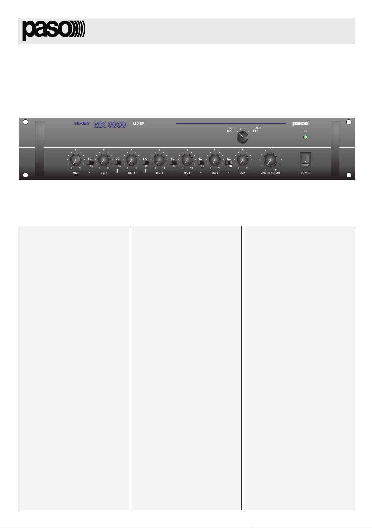
4.1 ACCENSIONE
Prima di mettere in funzione lapparecchio accertarsi di avere realizzato
correttamente tutte le connessioni. Portare linterruttore di rete [6] in
posizione ON o, in alternativa, applicare una sorgente di alimentazione
esterna in corrente continua a 24 V.
La spia luminosa ON [7] confermerà laccensione dellapparecchio.
4.2 SELEZIONE E CONTROLLO DEGLI INGRESSI
Selezionare, tramite il selettore rotativo [4], lingresso desiderato: CD,
TAPE, TUNER o LINE.
Regolare ora i controlli [1] e [3] per ottenere il desiderato livello di
equalizzazione tra le diverse sorgenti; per questa operazione si consiglia
di regolare il comando di volume principale [5] nellintorno di metà corsa.
Quando un ingresso non e utilizzato, è buona norma porre il relativo
regolatore di livello sulla posizione 0.
Per ogni ingresso microfonico è possibile attivare il filtro SC portando il
relativo deviatore [2] in posizione ON; il filtro inserisce una particolare
curva di equalizzazione che migliora intelligibilità del parlato.
4.3 CONTROLLO DI VOLUME PRINCIPALE
Il controllo di volume principale MASTER [5] regola il livello complessivo
del segnale di uscita, derivato dalla miscelazione dei vari segnali di ingresso.
Nel caso di più MX8033 (MX8033/117) collegati in cascata solo il
controllo MASTER dellultimo apparecchio della catena regola il livello
complessivo di tutti gli ingressi in miscelazione.
4.4 PRECEDENZA BASE AMPLIFICATA
Premendo il tasto di chiamata sulle basi amplificate della Serie B600,
collegate al relativo ingresso del miscelatore [19], si attiva la condizione
di precedenza, viene cioè opportunamente attenuato il livello dellingresso
ausiliario selezionato. E così possibile inviare un messaggio dalla base
microfonica senza sovrapposizione di segnale musicale.
4.5 PRECEDENZA AUTOMATICA
Un circuito elettronico provvede ad ammutolire automaticamente gli
ingressi AUX quando viene rilevata la presenza di segnale allingresso
BASE IN. È possibile in questo modo diffondere un messaggio vocale
semplicemente parlando al microfono, senza dover intervenire
manualmente per comandare lattenuazione del programma musicale.
Il livello di segnale necessario allattivazione della precedenza automatica
può essere regolato tramite il controllo A.P.T. (Automatic Precedence
Threshold) [18], accessibile dal pannello posteriore. La regolazione é
necessaria al fine di evitare lattivazione della precedenza automatica per
effetto di eventuali rumori di fondo raccolti dal microfono.
4.6 PRECEDENZA MICROFONICA
Gli ingressi microfonici del miscelatore, dal n° 2 al n ° 6, sono dotati di un
circuito di ammutolimento attivabile per mezzo dei contatti della
morsettiera PRECEDENCE [11]:
cortocircuitando il terminale + (uno dei due terminali comuni) con il
terminale I vengono ammutoliti gli ingressi microfonici 2, 3, 4, 5, 6 e
lingresso ausiliario selezionato,
cortocircuitando il terminale + con il terminale IIvengono ammutoliti
gli ingressi microfonici 3, 4, 5, 6 e lingresso ausiliario selezionato.
cortocircuitando il terminale + con il terminale IIIvengono ammutoliti
gli ingressi microfonici 4, 5, 6 e lingresso ausiliario selezionato.
cortocircuitando il terminale + con il terminale IVvengono ammutoliti
soltanto gli ingressi ausiliari.
Il microfono ad impugnatura PASO M906 e le basi microfoniche
(non amplificate) B601/B501-M sono predisposti per il collegamento
alla morsettiera PRECEDENCE. Per realizzare la connessione, inserire
la spina microfonica nellingresso desiderato, collegare il capocorda del
filo bianco al morsetto contrassegnato dalla lettera + (comune) e
quello del filo verde al morsetto corrispondente al livello di priorità
prescelto.
4.1 POWER UP
Before switching on the apparatus, make sure that all the connections
have been made correctly. Place the mains switch [6] to the ON
position or, as an alternative, apply an external 24 V DC source.
The ON indicator lamp [7] will light up to confirm that the apparatus is
switched on.
4.2 INPUTS SELECTION AND CONTROL
Using the rotary selector [4], select the desired input: TAPE, CD, TUNER
or LINE.
Now regulate the controls [1] and [3] to obtain the desired equalization
level between the various sources; to do this, we recommend that you
regulate the main volume control [5] to about the centre of its travel.
When an input is not used, its level regulator should always be set to
the 0 position.
For each microphone input, the SC filter can be activated by turning the
corresponding switch [2] to its ON position; the filter activates a special
equalization curve that makes the speech more intelligible.
4.3 MASTER VOLUME CONTROL
The main volume control MASTER [5] regulates the overall volume of
the output signal, obtained by mixing the various input signals. If more
than one MX8033 (MX8033/117) is cascaded, only the MASTER
control of the last device in the chain regulates the overall volume of all
the mixed inputs.
4.4 AMPLIFIED BASE PRECEDENCE
When the call key is pressed on the amplified bases in the B600 Series,
connected to corresponding input of the mixer [19], precedence condition
is activated, the level of the selected auxiliary input is therefore
attenuated. In this way, a message can be transmitted from the
microphone base without having to talk over the music.
4.5 AUTOMATIC PRECEDENCE
An electronic circuit automatically mutes the AUX inputs when the
presence of a signal is detected at the BASE IN input. In this way, a
voice message can be transmitted simply by talking into the microphone,
without having to turn down the music manually.
The level of the signal necessary to activate automatic precedence may
be regulated using the A.P.T. (Automatic Precedence Threshold) control
[18], accessible from the rear panel.
Regulation is necessary to avoid automatic precedence being activated
by background noise picked up by the microphone.
4.6 MICROPHONE PRECEDENCE
The microphone inputs of the mixer, from no. 2 to no. 6, are equipped
with a muting circuit which may be activated by means of the contacts
on the PRECEDENCE terminal strip [11]:
by short-circuiting the + terminal (one of the two common terminals)
with terminal I, microphone inputs 2, 3, 4, 5 and 6 and the selected
auxiliary input can be muted.
by short-circuiting the + terminal with terminal II, microphone
inputs 3, 4, 5 and 6 and the selected auxiliary input are muted.
by short-circuiting the + terminal with terminal III, microphone
inputs 4, 5 and 6 and the selected auxiliary input are muted.
by short-circuiting the + terminal with terminal IV, only the auxiliary
inputs are muted.
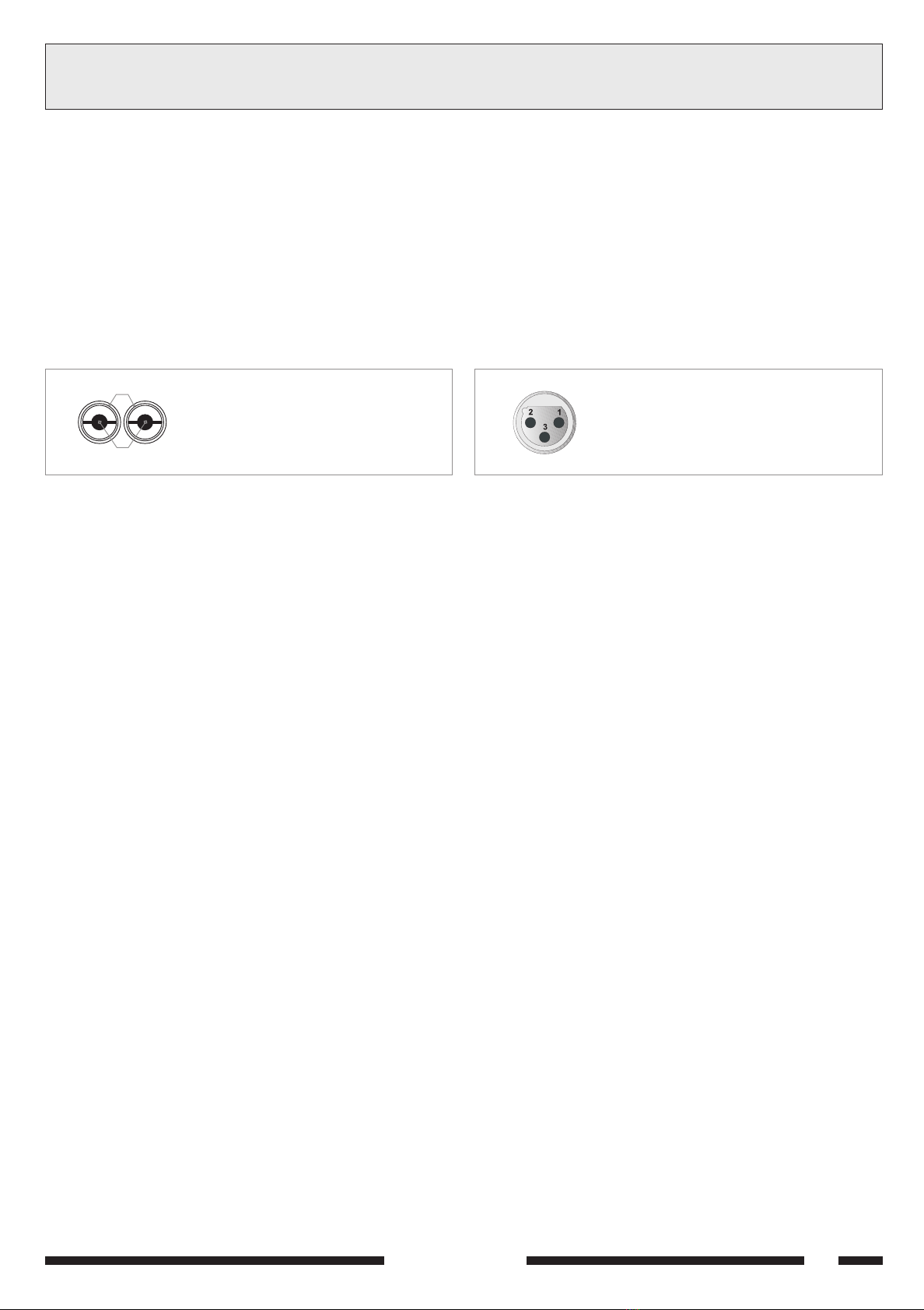
The PASO M906 handheld microphone and the B601/B501-M
microphone bases (non-amplified) are designed for connection to the
PRECEDENCE terminal strip. To make the connection, insert the
microphone plug in the desired input, connect the lug on the white wire
to the terminal marked + (common) and the lug on the green wire to
the terminal corresponding to the selected precedence level.
11-536.p65 03/12/01, 10.287

SERIE 8000
8
SERVICE NOTES5NOTE DI SERVIZIO
Fig. 5.2.1
5.1 AVVERTENZE
Le operazioni di seguito descritte richiedono laccesso allinterno
dellapparecchio. Si raccomanda di leggere attentamente le note a
riguardo nella sezione 2.3 NOTE DI SICUREZZA. Si ricorda, inoltre, che
gli interventi di questo tipo devono essere effettuati da personale
qualificato; la PASO S.p.A. declina ogni resposabilità in caso di
malfunzionamento dellapparecchio o di danni a cose o persone dovuti a
negligenza delloperatore.
Per accedere allinterno dellapparecchio occorre rimuovere il coperchio
sfilandolo dalla parte posteriore dopo aver tolto le relative viti di
fissaggio. Accertarsi, nel richiudere lapparecchio, di riposizionare la
rondella dentellata posta sotto una delle viti di fissaggio del coperchio;
questo allo scopo di assicurare un adeguato collegamento a terra anche
del coperchio realizzando un perfetto contatto elettrico tra questultimo
ed il telaio.
5.2 SOSTITUZIONE DEL FUSIBILE DI RETE
Il fusibile di rete è alloggiato nel corpo spina di rete [23]. Rimuovere il
cavo di rete ed estrarre il cassettino portafusibile (fig. 5.2.1).
Sfilare il fusibile guasto e sostituirlo solo con uno dello stesso tipo e
valore. Reinserire il cassettino portafusibile nel corpo spina e riallacciare
il cavo di rete.
5.3 SOSTITUZIONE DEL FUSIBILE INTERNO
Un fusibile posto allinterno dellapparecchio (lato trasformatore di
alimentazione) protegge il circuito di alimentazione esterna in corrente
continua da sovraccarichi o cortocircuiti.
Il valore del fusibile interno è riportato nelle vicinanze del relativo
portafusibile. Sostituire il fusibile solo con uno dello stesso tipo e valore.
5.4 INSTALLAZIONE DEI TRASFORMATORI MICROFONICI
Le schede PASO TM90 (trasformatore per ingresso microfonico), vanno
installate, ad apparecchio spento, negli appositi connettori CN100 e
CN101, posti in prossimità degli ingressi microfonici MIC.1 e MIC.2,
dopo avere rimosso i due ponticelli cortocircuitanti.
5.5 MODULI AGGIUNTIVI
Questo apparecchio è predisposto per linstallazione di moduli aggiuntivi
interni (modulo controllo toni, modulo generatore segnale di chiamata
(din-don), etc. Il pannello posteriore del mixer dispone di due aperture
[10] per poter accedere alle regolazioni dei moduli. Per il montaggio dei
moduli aggiuntivi allinterno del MX8033 (MX8033/117), ed il loro
utilizzo, si raccomanda di seguire attentamente le istruzioni allegate ai
moduli stessi.
5.1 WARNINGS
The operations described below require access to the inside of the
equipment. The notes on this subject contained in Section 2.3 SAFETY
NOTES must be read carefully. It should also be remembered that
activities of this type should be carried out by specialised personnel
only. PASO S.p.A. will not accept any liability in the event of
malfunctioning of the equipment or of damages to goods or persons
due to negligence on the part of the operator.
To access the inside of the apparatus, it is necessary to remove the
cover, sliding it out from the rear after removing the fixing screws.
Make sure, on re-closing the apparatus, that the shake-proof lock-
washer located under one of the fixing screws of the cover is put back
into place. The purpose of this is to ensure proper connection to earth
also of the cover by making perfect electrical contact between the
latter and the chassis.
5.2 REPLACEMENT OF THE MAINS FUSE
The mains fuse is housed in the body of the mains plug [23]. Disconnect
the power cable and remove the fuse-holder drawer (fig. 5.2.1).
Withdraw the damaged fuse and replace it using exclusively a fuse of the
same type and rating. Put the fuse-holder drawer back into place in the
body of the plug and reconnect the power cable.
5.3 REPLACEMENT OF THE INTERNAL FUSE
A fuse located inside the apparatus (near to the mains transformer)
protects the external DC power supply circuit from overloads and short
circuits. The rating of the internal fuse is shown in the vicinity of the
fuse-holder. Replace the fuse exclusively with another of the same
type and rating.
5.4 INSTALLATION OF MICROPHONE TRANSFORMERS
The PASO TM90 card (transformer for microphone input), are installed,
with the apparatus turned off, in the CN100 and CN101 connectors
slots, placed near the MIC.1 and MIC.2 inputs, provided for this
purpose, after removing the two jumpers.
5.5 ADDITIONAL MODULES
This equipment is designed for the installation of additional internal
modules (tone control module, call-signal generator module (chime),
etc.). There are two openings [10] in the rear panel of the module for
accessing the controls of the modules. When mounting the additional
modules inside the MX8033 (MX8033/117) and using them, make
sure you follow the instructions supplied with the modules carefully.
11-536.p65 03/12/01, 10.288

SERIE 8000 9
TECHNICAL SPECIFICATIONS6CARATTERISTICHE TECNICHE
ICINOFORCIMISSERGNI 3308XM 711/3308XM STUPNIENOHPORCIM
aznedepmi/àtilibisneS k1/Vm5,1 Ωecnadepmi/ytivitisneS
obrutsid/elangesotroppaR ABd86> oitarN/S
azneuqerfniatsopsiR )Bd3-(zH00071÷001 esnopseRycneuqerF
hceepsortlifnocazneuqerfniatsopsiR otiresnirotcerroc )Bd3-(zH00001÷093 hceepsdetresnihtiwesnopserycneuqerF retlifrotcerroc
IRAILISUAISSERGNI STUPNIYRAILIXUA
EPATeRENUTissergniaznedepmi/àtilibisneS k74/Vm002 Ωecnadepmi/ytivitisnesstupniEPATdnaRENUT
DCossergniaznedepmi/àtilibisneS k74/Vm005 Ωecnadepmi/ytivitisnestupniDC
ENILossergniaznedepmi/)elibaloger(àtilibisneS k74/V2÷2.0 Ωecnadepmi/).jda(ytivitisnestupniENIL
obrutsid/elangesotroppaR ABd08 oitarN/S
azneuqerfniatsopsiR )Bd3-(zH00012÷04 esnopseRycneuqerF
ATACIFILPMAESABOSSERGNI TUPNIESABDEIFILPMA
aznedepmi/àtilibisneS k74/Vm003 Ωecnadepmi/ytivitisneS
ETICSU STUPTUO
aticsuaznedepmi/olleviL 051/Vm577 Ωtuptuoecnadepmi/leveL
erotartsigerrepaticsuaznedepmi/olleviL k1/Vm002 Ωtuptuoredrocerecnadepmi/leveL
elanimonenoisrotsiD %1,0< noisrotsidlanimoN
OTNEMANOIZNUFIDINOIZIDNOC SNOITIDNOCGNITAREPO
eteradenoizatnemilA %01±V032 zH06/05 %01±V711 zH06/05 ylppusrewopsniaM
)eteradenoizatnemila(aznetopidomusnoC AV51 )ylppusrewopsniam(noitpmusnocrewoP
aunitnocetnerrocnianretseenoizatnemilA %51±V42 ylppusrewopCDlanretxE
)CCnianretseenoizatnemila(etnerrocidomusnoC )XAM(A7.0 )ylppusrewopCD.TXE(noitpmusnoctnerruC
)PxAxL(inoisnemiD mm513x89x284 )DxHxW(snoisnemiD
oseP gk1,4 thgieW
oiggaccotsid/avitarepoarutarepmeT C°07+÷C°04-/C°54+÷C°01- egnar.pmetegarots/egnar.pmetgnitarepO
avitaleràtidimU %59< ytidimuhevitaleR
azzeruciS otgnidrocca/amronodnoces 56006NEIEC ytefaS
11-536.p65 03/12/01, 10.289

SERIE 8000
10
LIST OF SPARE PARTS7LISTA DELLE PARTI DI RICAMBIO
ENOIZIRCSED 3308XM 711/3308XM NOITPIRCSED
esabotiucricemeissA 8944/72 ylbmessatiucriccisaB
ereittesromotiucricemeissA 9944/72 ylbmessatiucricspirtslanimreT
erotatummocotiucricemeissA 0054/72 ylbmessatiucrichctiwS
DELotiucricemeissA 1054/72 ylbmessatiucricsDEL
ittacsaerotatummoC 221/91 hctiwsepyt-petS
1aniboB µH41I 1 µlioCH
inoizisop2-V2erotatummoC 49/91 hctiwsnoitisop-2V2
azzerucisiderotasnednoC 222010907 -roticapacytefaS
eteriderotturretnI 99/91 hctiwssniaM
ailginaM ONV-243/83 eldnaH
)41x5,81Ø(aloponaM 65/82 )41x5,81Ø(bonK
)41x32Ø(aloponaM 85/82 )41x32Ø(bonK
otafargireselatnorfollennaP 1S-7332/63 lenaptnorfdetnirpneercs-kliS
k01ortemoiznetoP Ω).goL( 961/21 k01 Ω).goL(retemoitnetop
k74ortemoiznetoP Ω).niL( 251/21 k74 Ω).niL(retemoitnetop
otaroprocnielibisufnoceteridanipS 561/52 esufni-tliubhtiwgulpsniaM
enoizatnemilaiderotamrofsarT 691FT 711/691FT remrofsnartylppusrewoP
11-536.p65 03/12/01, 10.2810

SERIE 8000 11
1DESCRIPTION GÉNÉRALE
1.2 PANNEAU AVANT
[1] Contrôles de niveau des entrées micro.
[2] Filtres SPEECH CORRECTOR.
[3] Contrôle de niveau des entrées auxiliaires.
[4] Sélecteur des entrées auxiliaires.
[5] Contrôle de volume général.
[6] Interrupteur de réseau.
[7] Voyant dallumage.
1.3 PANNEAU ARRIERE
[8] Connexion de mise à la masse du châssis.
[9] Plaquette de connexion pour alimentation externe en courant continu.
[10] Contrôles des modules supplémentaires.
[11] Plaquettes de connexion pour la précédence microphonique.
[12] Sélecteur pour coupure d'alimentation phantom sur MIC1 et MIC2.
[13] Entrées microphoniques.
[14] Contrôle de niveau de l'entrée LINE.
[15] Entrées auxiliaires.
[16] Sortie pour enregistreur.
[17] Contrôle de niveau de l'entrée BASE.
[18] Contrôle du seuil d'activation de priorité automatique.
[19] Entrée base micro amplifiée.
[20] Sortie du signal mixé.
[21] Sortie d'extension.
[22] Entrée d'extension.
[23] Fiche de réseau avec fusible incorporé.
1.1 INTRODUCTION
Le préamplificateur-mixeur PASO MX8033 (MX8033/117) est un
appareil aux caractéristiques techniques de haut niveau; sa grande
souplesse et grande simplicité d'utilisation lui permettent de s'adapter à
de très nombreuses applications professionnelles.
Ses caractéristiques techniques sont les suivantes:
6 entrées micro équilibrées électroniquement - possibilité d'équilibrage
avec transformateur (option) sur 2 des 8 entrées.
4 entrées auxiliaires sélectionnables dont une avec contrôle de
sensibilité.
sortie équilibrée à haut niveau.
sortie auxiliaire pour enregistreur.
entrée et sortie du bus de mixage pour extension entrées.
entrée base amplifiée avec priorité automatique.
filtre Speech corrector activable sur toutes les entrées micro.
alimentation Phantom pour micros à condensateur.
priorité micro à plusieurs niveaux.
adapté pour modules internes supplémentaires.
Pour obtenir les performances maximum de l'appareil, il est recommandé
de bien lire les instructions ci-dessous.
1.1 EINLEITUNG
Der Vorverstärker-Mixer PASO MX8033 (MX8033/117) ist ein Gerät
mit modernen technischen Eigenschaften. Aufgrund seiner Vielseitigkeit
und Einfachheit in der Handhabung ist es für viele professionelle
Anwendungen geeignet. Seine technischen und funktionalen
Haupteigenschaften können wie folgt zusammengefaßt werden:
sechs elektronisch symmetrierte Mikrofoneingänge - Möglichkeit
der Symmetrierung von zwei dieser Eingänge mit Hilfe eines
Transformators (optional).
vier wählbare Hilfseingänge, davon einer mit Empfindlichkeitsregelung.
hochstufiger, symmetrierter Ausgang.
Hilfsausgang für Aufnahmegerät.
Eingang und Ausgang des Bus des Mixers für die Erweiterung der Eingänge.
Eingang für verstärkte Sprechstelle mit automatischem Vorrang.
Filter Speech Corrector, der auf allen Mikrofoneingängen aktiviert
werden kann.
Phantomeinspeisung für Kondensatormikrofone.
Mehrstufige Mikrofonvorrangschaltung.
Voreinstellung für die Aufnahme von zusätzlichen internen Karten.
Um die Vorteile des Geräts maximal nutzen zu können, wird empfohlen,
die nachstehenden Anweisungen sorgfältig zu lesen.
ALLGEMEINE BESCHREIBUNG
1.2 FRONTPLATTE
[1] Stufenkontrolle der Mikrofoneingänge.
[2] Filter SPEECH CORRECTOR.
[3] Stufenkontrolle der Hilfseingänge.
[4] Wählschalter der Hilfseingänge.
[5] Allgemeine Lautstärkekontrolle.
[6] Netzschalter.
[7] Einschalt-LED.
1.3 RÜCKPANEEL
[8] Erdschutzverbindung des Gehäuses.
[9] Klemmenbrett für die externe Gleichstromversorgung.
[10] Regler für zusätzliche Module.
[11] Klemmenbrett für die Mikrofonprioritäten.
[12] Wählschalter für den Ausschluß der phantom-Einspeisung (MIC1 /MIC2).
[13] Mikrophoneingänge.
[14] Stufenkontrolle des Eingangs LINE.
[15] Hilfseingänge.
[16] Ausgang für Aufnahmegerät.
[17] Stufenkontrolle des Eingangs BASE.
[18] Stufenkontrolle der Ansprechschwelle der automatischen Vorrangschaltung.
[19] Eingang für verstärkte Mikrofonsprechstelle.
[20] Ausgang des Mischsignals.
[21] Erweiterungsausgang.
[22] Erweiterungeingang.
[23] Netzstecker mit integrierter Sicherung.
11-536.p65 03/12/01, 10.2811

SERIE 8000
12
2PRECAUTIONS GÉNÉRALES
2.1 INSTALLATION
Tous les appareils PASO sont construits en respectant les normes
internationales de sécurité les plus sévères et conformément aux normes
requises par la Communauté Européenne. Pour une utilisation correcte
et efficace de lappareil il est important de prendre connaissance de
toutes ses caractéristiques en lisant attentivement les présentes
instructions et notamment les notices de sécurité. Il est nécessaire une
juste ventilation à lappareil lors de son fonctionnement. Ne pas enfermer
lappareil dans un meuble sans aération et ne pas obstruer les fissures
daération en posant des objets ou accessoires sur la partie supérieure
de lappareil. Eviter en outre de placer lappareil à proximité de sources
de chaleur. Le mixer est prévu pour être installé sur rack de 19; pour ce
type dinstallation enlever auparavant les quatre pieds dappui, puis
fixer lappareil au rack en utilisant les vis et les rondelles fournies.
Avant dallumer lappareil, contrôler que toutes les entrées et les sorties
sont correctement branchées.
2.2 ALIMENTATION ET MISE A LA TERRE
Lappareil est prévu pour fonctionner avec une tension de réseau de
230 V ± 10% 50/60 Hz (117 V ± 10% 50/60 Hz pour la version
MX8033/117). En alternative il est possible dalimenter lappareil
avec une tension continue extérieure de +24 V. Habituellement, cette
tension, qui doit être appliquée en respectant les polarités à chaque
borne de la plaquette de connexion [9], est fournie par des
accumulateurs maintenus sous charge tampon et entre en fonction
seulement en cas durgence; il est nécessaire, dans ce cas, de prévoir
lutilisation dun relais extérieur qui connecte les batteries à lappareil
uniquement lorsque lalimentation de réseau est coupée.
Conformément aux normes de sécurité, linterrupteur dallumage [6]
agit uniquement sur la tension de réseau.
Lappareil est protégé par des fusibles pour les deux types dalimentation:
consulter le chapitre 5 NOTICES DE SERVICE pour leur substitution
éventuelle. Lappareil est muni dun cordon dalimentation avec fil de terre
et la cosse correspondante sur la fiche de réseau ne doit être enlevée en
aucun cas. Sassurer que la prise de courant est équipée de connexion de
terre conforme aux normes en vigueur.
2.3 CONSEILS DE SECURITE
Toute intervention à lintérieur de lappareil, comme la sélection de certains
modes demploi, lapplication daccessoires ou la substitution de fusibles,
doit être exclusivement effectuée par un personnel expert: le retrait du
couvercle rend accessibles certaines parties présentant des risques
délectrocution.
Avant denlever le couvercle, contrôler toujours que le cordon
dalimentation est débranché.
En cas de chute accidentelle de liquides sur lappareil, débrancher
immédiatement la fiche dalimentation et contacter le centre dassistance
PASO le plus proche. Il est possible de relier dautres appareils à la
connexion de masse du châssis [8] seulement pour la fonction de
protection des signaux à bas niveau: cette prise ne doit pas être utilisée
pour la connexion de sécurité du châssis à la terre.
ALLGEMEINE HINWEISE
2.1 INSTALLATION
Alle PASO - Geräte sind gemäß den strengsten internationalen
Sicherheitsvorschriften und unter Einhaltung der Anforderungen
der Europäischen Gemeinschaft gebaut. Der korrekte und effiziente
Einsatz des Geräts setzt die Kenntnis aller Eigenschaften und
dementsprechendes Lesen dieser Gebrauchsanleitung, insbesondere
der Sicherheitsanweisungen voraus. Während des Betriebs des Geräts
muß eine ausreichende Lüftung gewährleistet sein. Das Einschließen
des Geräts in einen nicht gelüfteten Schrank oder der Verschluß von
Lüftungsöffnungen durch Abstellen von Objekten soll vermieden werden.
Das Gerät nicht in der Nähe von Wärmequellen aufstellen.
Der Mixer kann in einem 19 Rack montiert werden. Hierzu müssen die
vier Aufstellfüßchen am Geräteboden entfernt werden, danach wird
das Gerät mit Hilfe der beiliegenden Schrauben und Unterlegscheiben
im Rack befestigt. Vor der Inbetriebnahme ist sicherzustellen, daß alle
Ein- und Ausgänge richtig angeschlossen sind.
2.2 EINSPEISUNG UND ERDUNG
Das Gerät ist für den Netzbetrieb bei 230 V ± 10% 50/60 Hz (117 V ± 10%
50/60 Hz für die Version MX8033/117) vorgesehen.
Alternativ hierzu besteht die Möglichkeit, das Gerät mit externer
Gleichspannung von +24 V zu versorgen. Normalerweise wird diese
Spannung, unter Beachtung der Polaritäten der entsprechenden
Anschlüsse am Klemmenbrett [9], über puffergeladene Akkumulatoren
angelegt und kommt nur in Notfällen zum Einsatz; in diesem Fall ist es
notwendig, ein externes Relais einzusetzen, das die Batterie nur bei
Ausfall des Netzstroms schaltet.
Wie von den Sicherheitsvorschriften gefordert, betätigt der Netzschalter
[6] nur die Netzversorgung.
Das Gerät ist für beide Arten der Einspeisung mit Schmelzsicherungen
geschützt: vor Auswechseln ist der Anschnitt 5 SERVICEANWEISUNGEN
zu lesen. Das Gerät ist mit einem Einspeisungskabel mit Erdleiter
ausgestattet und der entsprechende Anschluß am Netzstecker darf auf
keinen Fall entfernt werden. Sicherstellen, daß die Netzsteckdose mit
einem vorschriftsmäßigen Erdleiter ausgerüstet ist.
2.3 SICHERHEITSANWEISUNGEN
Jeder Eingriff im Innern des Geräts, wie die Wahl einiger Anwendungen,
die Montage von Zubehör oder das Auswechseln von Schmelzsicherungen
darf nur von Fachpersonal vorgenommen werden: die Entfernung des
Deckels legt Komponenten mit Stromschlaggefahr frei.
Vor Öffnen des Deckels ist immer sicherzustellen, daß der Netzstecker
abgezogen ist.
Bei versehentlichem Vergießen von Flüssigkeiten auf dem Gerät muß der
Netzstecker unverzüglich abgezogen und das nächste PASO
Kundendienstzentrum verständigt werden. Die Verbindung des
Erdschutzleiters des Gehäuses [8] erlaubt auch die Verbindung anderer
Geräte, allerdings mit auschließlicher Schutzfunktion gegen
Niederfrequenzsignale: dieser Anschluß darf nicht für die Verbindung des
Erdschutzleiters verwendet werden.
11-536.p65 03/12/01, 10.2812

SERIE 8000 13
1: blindage / Abschirmung
2: signal (côté chaud) / Signal (warme Seite)
1: blindage / Abschirmung
2: signal (côté chaud) / Signal (warme Seite)
3: signal (côté froid) / Signal (kalte Seite)
Fig./Abb. 3.1.1 Fig./Abb. 3.2.1
1
2
3CONNEXIONS
3.1 CRITERES GENERAUX
Pour un fonctionnement correct de lappareil, il est nécessaire dobserver
certains critères généraux concernant lexécution des connexions de
linstallation damplification:
ne pas placer de câbles et microphones sur le meuble de lappareil.
ne pas poser les lignes de signal en parallèle à celles du réseau
électrique; respecter une distance minimum de 30/40 cm.
placer les lignes dentrée et les lignes de sortie (haut-parleurs) loin les
unes des autres.
positionner les microphones en dehors de langle de radiation des
diffuseurs sonores afin déviter le phénomène de réaction acoustique
(effet Larsen).
Les prises coaxiales de type PHONO effectuent une connexion déséquilibrée
(voir fig. 3.1.1 pour les connexions relatives à ce type de connecteurs).
3.2 ENTREES MICROPHONIQUES
Lappareil présente six entrées [13] pour microphones dynamiques à
basse impédance ou pour microphones à électrète. Les prises dentrée
sont de type XLR femelle (la fig. 3.2.1 reporte les connexions en question
vues de lextérieur).
Toutes les entrées microphoniques sont équilibrées électroniquement
pour obtenir une rejet élevé des perturbations de type commun. En cas
de situations dinstallation particulières où il est requis une isolation
galvanique entre la source et le mixer, il est possible déquiper chaque
entrée microphonique dun transformateur équilibré (en option) code
PASO TM90. Voir au chapitre 5, la description de la procédure pour
linstallation de cet accessoire; parmi les exemples typiques de sources
qui peuvent nécessiter ce désaccoupplement, citons les lignes
téléphoniques ou bien les signaux en sortie de certaines cartes
particulières dordinateur. Un filtre spécial - speech corrector - peut
être activé sur chaque entrée micro à l'aide de l'interrupteur
correspondant [2]. Ce filtre permet d'améliorer la clarté audio en
renforçant la bande de fréquences correspondante.
Toutes les entrées micro fournissent une alimentation PHANTOM de
12 V pour micros à électret (par exemple modèle PASO MC200).
ATTENTION: certains type de micros dynamiques avec sortie
déséquilibrée risquent d'être définitivement endommagés en cas de
branchement à une entrée avec alimentation PHANTOM activée.
L'alimentation PHANTOM peut être coupée sur les entrées MIC1 et
MIC2 par l'intermédiaire du sélecteur PHANTOM OFF [12].
3.3 ENTREES AUXILIAIRES
Quatre entrées [15] ad hoc sont prévues pour la connexion du mixer à
des sources auxiliaires (CD, TUNER, TAPE et LINE); l'entrée LINE est
dotée d'un contrôle de sensibilité [14]. Le sélecteur [4] sur le panneau
avant permet de sélectionner une entrée auxiliaire alors que le contrôle
AUX [3] permet den régler le niveau.
La double prise PHONO permet lutilisation dun câble stéréo standard; le
mélange des deux canaux a lieu à lintérieur du mixer. Si la source est de
type monophonique, il est possible dutiliser indifféremment lune ou lautre
prise.
ANSCHLÜSSE
3.1 ALLGEMEINE HINWEISE
Für einen korrekten Betrieb des Gerätes müssen folgende Hinweise für
die Anschlüsse beachtet werden:
das Ablegen von Kabeln und Mikrofonen auf dem Geräteschrank
vermeiden.
die parallele Legung der Signallinien mit den elektrischen Leitungen
vermeiden und einen Abstand von mindestens 30/40 cm einhalten.
die Eingangs- und Ausgangslinien (Lautsprecher) entfernt voneinander
positionieren.
die Mikrofone außerhalb des Ausstrahlungswinkels der Lautsprecher
aufstellen, um die Rückkoppelung zu vermeiden (Larsen-Effekt).
Die koaxialen PHONO-Buchsen stellen eine nicht symmetrierte Verbindung
her; die Abbildung. 3.1.1 stellt die Verbindungen dieser Art von
Anschlüssen dar.
3.2 MIKROFONEINGÄNGE
Es stehen sechs Eingänge [13] für bewegliche Mikrofone mit niedriger
Impedanz oder Elektret-Mikrofone zur Verfügung. Die Eingangsbuchsen
sind vom Typ XLR; die Abbildung 3.2.1 zeigt die Verbindungen aus
Außenansicht.
Alle Mikrofoneingänge sind elektronisch symmetriert, um einen hohen
Abschattungsgrad des Umgebungslärms zu gewährleisten. Bei
besonderen Gegebenheiten der Anlage, für die eine galvanische
Isolierung zwischen Quelle und Mixer notwendig ist, besteht die
Möglichkeit, jeden Mikrofoneingang mit einem ausgesteuerten
Transformator (optional) Art. PASO TM90 auszustatten. Im Abschnitt
5 wird die Vorgehensweise bei der Installation dieses Zubehörs
beschrieben; typische Beispiele für eine notwendige Entkopplung können
Telefonlinien oder Ausgangssignale von besonderen Computerkarten
sein. Ein besonderer Filter, genannt "speech corrector", kann für jeden
Mikrofoneingang durch Betätigen der entsprechenden Taste [2] aktiviert
werden. Die Verwendung dieses Filters verbessert die Verständlichkeit
der Sprache durch Hervorhebung des entsprechenden Frequenzbands.
Alle Mikrofoneingänge besitzen eine 12 V PHANTOM-Einspeisung für die
Versorgung von Elektretmikrofonen (z.B. Modell PASO MC200).
ACHTUNG: einige Arten von dynamischen Mikrofonen mit nicht
symmetriertem Ausgang können irreparabel beschädigt werden, wenn
sie an einen Eingang mit eingeschalteter PHANTOM-Einspeisung
angeschlossen werden. An den Eingängen MIC. 1 und MIC. 2 kann
die PHANTOM-Einspeisung durch Drücken der Taste PHANTOM OFF
[12] ausgeschaltet werden.
3.3 HILFSEINGÄNGE
Für den Anschluß des Mixers an Hilfsquellen (CD, TUNER, TAPE und
LINE) sind vier Eingänge [15] vorgesehen; der Eingang LINE besitzt
eine Empfindlichkeitsregelung [14]. Der Wahlschalter [4] auf der
Frontplatte ermöglicht die Anwahl eines Hilfseingangs, während die
AUX - Kontrolle [3] die entsprechende Stufe reguliert. Die doppelte
PHONO-Buchse ermöglicht die Verwendung eines Standard-
Stereokabels; die Mischung der beiden Kanäle erfolgt im Innern des
Mixers. Bei Monofoniequellen können unterschiedslos beide Arten von
Buchsen verwendet werden.
11-536.p65 03/12/01, 10.2813

SERIE 8000
14
3CONNEXIONS
1: précédence / Priorität
2: blindage / Abschirmung
3: signal (côté chaud) / Signal (warme Seite)
4: +12 V
5: masse / Erdung
1: blindage / Abschirmung
2: signal (côté chaud) / Signal (warme Seite)
3: signal (côté froid) / Signal (kalte Seite)
Fig./Abb. 3.6.1Fig./Abb. 3.5.1
3.4 SORTIE POUR ENREGISTREUR
La double prise phono TAPE OUT [16] permet de relier le mixer à un
enregistreur à bande pour lenregistrement du programme en sortie.
Lamplitude du signal disponible à cette prise est indépendant du réglage
du volume général (contrôle MASTER [5] ).
3.5 ENTREE BASE AMPLIFIEE
La prise DIN à 5 pôles BASE IN [19] permet la connexion du mixeur aux
bases préamplifiées PASO Série B600, jusqu'à un maximum de six.
La figure 3.5.1 montre les branchements de la prise (vue de l'extérieur)
ainsi que les différents signaux d'alimentation.
Le niveau du signal transmis à la prise BASE peut être réglé par
l'intermédiaire du potentiomètre [17].
Cette prise peut également être utilisée pour:
entrée supplémentaire à basse fréquence non asservie à l'atténuation
de priorité et utilisable éventuellement pour l'activation de la fonction
de priorité automatique (voir Chap. 4.5);
alimentation d'un dispositif externe en tension stabilisée de 12Vcc; la
distribution maximum de courant est de 500mA avec pics maximum
de 1A.
3.6 SORTIE MIXÉE
La sortie du mixeur BAL. MIX. OUT [20] est équilibrée électroniquement
et dispose d'un connecteur XLR mâle; la figure 3.6.1 illustre les connexions
à ce connecteur vues de lextérieur. Il est possible deffectuer une
connexion de type non équilibrée en utilisant seulement les bornes 2
(pôle chaud) et 1 (masse) de la prise.
3.7 ENTREE/SORTIE D'EXTENSION
Il est possible d'étendre les capacités fonctionnelles de l'appareil en
augmentant le nombre de sorties; à cet effet sont présentes deux prises
pour le branchement en chaîne de deux mixeurs ou plus.
La sortie EXP. OUT [21] du premier mixeur doit être reliée à l'entrée
EXP. IN [22] du mixeur suivant et ainsi de suite. La sortie MIX. OUT
[20] du dernier mixeur doit être reliée à l'amplificateur.
NOTE: seul le contrôle de niveau MASTER [5] du dernier mixeur permet
en ce cas de régler le niveau général de toutes les entrées.
3.8 BORNIER DE PRIORITE
Les contacts du bornier PRECEDENCE [11] permettent d'activer la
fonction de priorité micro (en coupant certaines entrées micro et/ou l'entrée
auxiliaire sélectionnée). Certains appareils PASO, ainsi le micro M906 et
les bases B601/B501-M, sont prévus pour cette fonction; ils sont à cet
effet dotés de deux connecteurs à relier aux borniers de PRECEDENCE.
3.9 CONTROLES SUPPLEMENTAIRES
Le mixeur MX8033 (MX8033/117) est prévu pour l'installation
éventuelle de modules supplémentaires externes; les ouvertures A et
B [10], au dos de l'appareil, permettent d'accéder aux contrôles de ces
mêmes modules (voir Chap. 5.5).
ANSCHLÜSSE
3.4 AUSGANG FÜR DAS AUFNAHMEGERÄT
Die doppelte Phonobuchse TAPE OUT [16] ermöglicht den Anschluß
des Mixers an ein Bandaufnahmegerät, um das ausgesendete Programm
aufzunehmen. Die verfügbare Signalamplitüde dieser Buchse ist unabhängig
von der allgemeinen Lautstärkeregelung (MASTER -Kontrolle [5]).
3.5 EINGANG VERSTÄRKTE SPRECHSTELLE
Die 5-polige DIN-Buchse BASE IN [19] ermöglicht den Anschluß eines
Mixers an bis zu maximal sechs vorverstärkte Sprechstellen der Serie
PASO B600. Die Abbildung 3.5.1 zeigt die Anschlüsse der Buchse aus
Außenansicht mit den entsprechenden Signalen und Einspeisungen.
Die an die Buchse BASE gesandte Signalstufe kann mit Hilfe des
Potentiometers [17] eingestellt werden.
Es besteht die Möglichkeit, diese Buchse auch für andere Zwecke zu
verwenden:
für einen zusätzlichen Niederfrequenzeingang, der nicht der
Abschwächung durch die Vorrangschaltung unterliegt und gegebenenfalls
für die Vorrangerzeugung verwendet werden kann (vgl. 4.5)
Einspeisung eines externen Geräts mit stabilisierter 12V
Gleichspannung; die maximale Stromabgabe entspricht durchschnittlich
500 mA mit Spitzen bis zu 1 A.
3.6 MISCHAUSGANG
Der Ausgang des Mixers BAL. MIX. OUT [20] ist elektronisch symmetriert
und verfügt über einen XLR-Stecker; die Abbildung 3.6.1 zeigt die
Anschlüsse an diesen Verbinder aus Außenansicht. Es ist möglich, eine
nicht symmetrierte Verbindung herzustellen, indem die Terminale 2
(warmer Pol) und 1 (Erdung) der Buchse verwendet werden.
3.7 ERWEITERUNGSEINGANG/-AUSGANG
Die Betriebskapazität des Geräts kann mit Hilfe der Erhöhung der Anzahl
der Eingänge heraufgesetzt werden; zu diesem Zweck sind zwei Buchsen
für den Anschluß in Kaskadenschaltung von zwei oder mehreren Mixern
vorhanden. Der Ausgang EXP. OUT [21] des ersten Mixers muß an den
Eingang EXP. IN [22] nächsten Geräts angeschlossen werden, usw.
Der Ausgang MIX. OUT [20] des letzten Mixers wird an den Eingang der
Verstärkeranlage angeschlossen.
MERKE: nur die Stufenkontrolle MASTER [5] des letzten Mixers der
Reihe wirkt auf die allgemeine Stufe aller Eingänge.
3.8 KLEMMENBRETT FÜR DIE VORRANGSCHALTUNG
Über die Kontakte des Klemmenbretts PRECEDENCE [11] kann die
Betriebsbedingung für die Vorrangschaltung (Abschwächung einiger
Mikrofoneingänge und/oder des gewählten Hilfseingangs) eingestellt
werden. Einige Produkte von PASO wie beispielsweise das Mikrofon
M906 und die Sprechstellen B601/B501-M, sind bereits für diese
Funktion ausgelegt, d.h. sie besitzen zwei Kabelschuhe, die an das
Klemmenbrett PRECEDENCE angeschlossen werden müssen.
3.9 ZUSÄTZLICHE KONTROLLEINHEITEN
Der Mixer MX8033 (MX8033/117) ist für die Aufnahme von zusätzlichen
internen Modulen konzipiert. Die Öffnungen A und B [10], auf der
Rückseite des Geräts sind dementsprechend für den Zugang zu den
Kontrollen dieser Module bestimmt (siehe Abschnitt 5.5).
11-536.p65 03/12/01, 10.2814

SERIE 8000 15
4UTILISATION DE L'APPAREIL
4.1 MISE EN MARCHE
Avant de mettre lappareil en marche, sassurer davoir réalisé
correctement toutes les connexions et davoir effectué tous les réglages
nécessaires (mode de fonctionnement, sélection de lentrée auxiliaire,
etc.). Placer linterrupteur de réseau [6] en position ON ou bien, en
alternative, appliquer une source dalimentation extérieure en courant
continu à 24 V. Le voyant lumineux POWER [7] confirmera lallumage de
lappareil.
4.2 SELECTION ET CONTROLE DES ENTREES
Sélectionner l'entrée désirée, par l'intermédiaire du sélecteur [4]: CD,
TAPE, TUNER ou LINE. Régler ensuite les contrôles [1] et [3] pour
obtenir le niveau d'égalisation voulu entre les différentes sources; pour
effectuer cette opération, il est recommandé de régler le volume principal
[5] à mi-puissance environ. Le réglage de niveau d'une entrée non utilisée
doit en principe se trouver sur la position 0. Pour chaque entrée micro,
il est possible d'activer le filtre SC en plaçant le sélecteur [2]
correspondant sur la position ON; le filtre active une courbe d'égalisation
spécifique qui a pour effet d'améliorer la clarté audio.
4.3 CONTROLE DE VOLUME GENERAL
La contrôle de volume général MASTER [5] règle le niveau général du
signal de sortie résultant du mixage des différents signaux d'entrée.
Dans le cas où l'installation est constituée de plusieurs MX8033
(MX8033/117) reliés en chaîne, seul le contrôle MASTER du dernier
appareil permet de régler le niveau général de toutes les entrées mixées.
4.4 PRIORITE BASE AMPLIFIEE
La touche d'appel des bases amplifiées Série B600 reliées à l'entrée
correspondante du mixeur [19], permet d'activer la fonction de priorité;
le niveau de l'entrée auxiliaire sélectionnée est abaissé et il devient ainsi
possible d'envoyer un message depuis la base micro sans que message et
sources musicales ne se superposent.
4.5 PRIORITE AUTOMATIQUE
Un circuit électronique coupe automatiquement les entrées AUX lorsqu'est
relevée la présence du signal au niveau de l'entrée BASE IN. Ceci permet
de diffuser un message vocal depuis le micro sans devoir effectuer
d'opération manuelle pour abaisser le volume du programme musical.
Le niveau du signal nécessaire à l'activation de la fonction de priorité
automatique peut être réglé par l'intermédiaire du contrôle A.P.T.
(Automatic Precedence Threshold) [18] accessible depuis le panneau
postérieur. Le réglage est nécessaire afin d'éviter l'activation indésirable
de la priorité automatique à cause de bruits de fond captés par le micro.
4.6 PRIORITE MICRO
Les entrées micro du mixeur, de la n° 2 à la n° 6, sont dotées d'un circuit
de coupure activable par l'intermédiaire des contacts du bornier
PRECEDENCE [11]:
en court-circuitant la borne + (une des deux bornes communes)
avec la borne I, est obtenue la coupure des entrées micros 2, 3, 4,
5 et 6 et de l'entrée auxiliaire sélectionnée.
en court-circuitant la borne + avec la borne II, est obtenue la
coupure des entrées micros 3, 4, 5 et 6 et de l'entrée auxiliaire
sélectionnée.
en court-circuitant la borne + avec la borne III, est obtenue la
coupure des entrées micros 4, 5 et 6 et de l'entrée auxiliaire
sélectionnée.
en court-circuitant la borne + avec la borne IV, est obtenue la
coupure des entrées auxiliaires uniquement.
Le micro à poignée PASO M906 et les bases micro (non amplifiées) B601/
B501-M sont prévus pour la connexion au bornier PRECEDENCE. Pour
effectuer cette connexion, raccorder la fiche micro à l'entrée désirée,
relier le connecteur du fil blanc à la borne marquée du signe + (commun)
et le connecteur du fil vert à la borne correspondant au niveau de priorité
désiré.
GEBRAUCH DES GERÄTS
4.1 EINSCHALTEN
Vor der Inbetriebnahme des Geräts ist sicherzustellen, daß alle
Verbindungen und alle notwendigen Regulierungen korrekt vorgenommen
worden sind (Betriebsart, Wahl der Hilfseingänge, etc.).
Den Netzschalter [6] in Position ON bringen, oder alternativ die externe
Einspeisung mit 24 V Gleichstrom anlegen. Die Kontrolleuchte POWER
[7] bestätigt die Einschaltung des Geräts.
4.2 AUSWAHL UND REGULIERUNG DER EINGÄNGE
Mit Hilfe des Drehschalters [4] den gewünschten Eingang auswählen:
CD, TAPE, TUNER oder LINE. Anschließend die Regler [1] und [3]
einstellen, um die gewünschte Abstimmung der verschiedenen Quellen zu
regulieren. Hierfür ist es empfehlenswert, den Hauptlautstärkeregler [5]
auf ungefähr Mitte zu setzen. Falls ein Eingang nicht benötigt wird, sollte
die Stufenregulierung auf die Position 0 gesetzt werden. Der Filter SC
kann für jeden Mikrofoneingang mit Hilfe des entsprechenden Abweichers
[2] in der Position ON aktiviert werden; der Filter schaltet eine besondere
Abstimmkurve, die die Sprache verständlicher macht.
4.3 HAUPTLAUTSTÄRKEREGLER
Der Hauptlautstärkeregler MASTER [5] reguliert die gesamte
Signalausgangsstufe, die von der Mischung der unterschiedlichen
Eingangssignale generiert wird. Bei mehreren Geräten MX8033
(MX8033/117), die in Kaskadenschaltung verbunden sind, reguliert
nur der Regler MASTER des letzten Geräts die gesamte Stufe aller
gemischten Ausgänge.
4.4 VORRANGSCHALTUNG DER VERSTÄRKTEN SPRECHSTELLE
Durch Betätigen der Meldetasten auf den verstärkten Sprechstellen der
Serie B600, die an den entsprechenden Ausgang des Mixers [19]
angeschlossen sind, wird der Vorrangbetrieb eingeschaltet, d.h. es wird
das Signal des aktiven Hilfseingangs abgeschwächt. Auf diese Weise ist
die Sendung einer Durchsage von der Mikrofonsprechstelle möglich ohne
daß diese vom Musiksignal überlagert wird.
4.5 AUTOMATISCHER VORRANG
Ein elektronischer Schaltkreis sorgt für die automatische Abschwächung
der AUX-Eingänge, wenn ein Signal am Eingang BASE IN registriert
wird. So kann eine Ansage durch einfaches Sprechen in das Mikrofon
durchgegeben werden, ohne daß manuell die Abschwächung des
Musikprogramms geschaltet werden muß.
Die für die Aktivierung der automatischen Vorrangschaltung notwendige
Signalstufe kann über den Regler A.P.T. (Automatic Precedence
Threshold) [18] eingestellt werden, der sich auf dem Rückpaneel befindet.
Die Regulierung ist erforderlich, um die Auslösung der automatischen
Vorrangschaltung durch eventuelle Hintergrundgeräusche, die vom
Mikrofon aufgenommen werden, zu vermeiden.
4.6 MIKROFONVORRANG
Die Mikrofoneingänge des Mixers Nr. 2 bis Nr.6 besitzen eine
Abschwächungsschaltkreis, der über die Kontakte des Klemmenbretts
PRECEDENCE [11] aktiviert wird:
durch Kurzschließen des Endstücks + (einer der beiden gemeinsamen
Endstücke) mit dem Endstück I werden die Mikrofoneingänge 2, 3,
4, 5, 6 und der gewählte Hilfseingang abgeschwächt,
durch Kurzschließen des Endstücks + mit dem Endstück II werden
die Mikrofoneingänge 3, 4, 5, 6 und der gewählte Hilfseingang
abgeschwächt.
durch Kurzschließen des Endstücks + mit dem Endstück III werden
die Mikrofoneingänge 4, 5, 6 und der gewählte Hilfseingang
abgeschwächt
durch Kurzschließen des Endstücks + mit dem Endstück IV werden
nur die gewählten Hilfseingänge abgeschwächt.
Das Handmikrofon PASO M906 und die Mikrofonsprechstelle (nicht
verstärkt) B601/B501-M sind für den Anschluß an das Klemmenbrett
PRECEDENCE ausgelegt. Zur Herstellung der Verbindung muß der
Mikrofonstecker in den entsprechenden Eingang gesetzt werden, der
Kabelschuh des weißen Leiters an die mit + (gemeinsam)
gekennzeichnete Klemme und der des grünen Leiters an die Klemme der
gewünschten Vorrangstufe angeschlossen werden.
11-536.p65 03/12/01, 10.2815

SERIE 8000
16
5NOTICES DE SERVICE
Fig. 5.2.1
5.1 PRECAUTIONS
Les opérations décrites ci-après nécessitent laccès à lintérieur de
lappareil. Lire attentivement à ce propos les informations reportées au
paragraphe 2.3 NOTICES DE SECURITE. A rappeler, en outre, que les
interventions de ce type doivent être effectuées par un personnel
expert; PASO S.p.A. décline toute responsabilité en cas de mauvais
fonctionnement de lappareil ou de dommages aux choses ou aux
personnes dus à la négligence de lopérateur. Pour accéder à lintérieur
de lappareil, enlever le couvercle en lextrayant par la partie arrière
après avoir enlevé les vis de retenue. Se rappeler, au moment de la
fermeture de lappareil, de remettre la rondelle dentelée présente sous
une des vis de retenue du couvercle; celle-ci sert à assurer une juste
connexion à la terre du couvercle en réalisant un contact électrique
parfait entre ce dernier et le châssis.
5.2 SUBSTITUTION DU FUSIBLE DALIMENTATION
Le fusible dalimentation est logé dans le corps de la fiche dalimentation
[23]. Débrancher le cordon dalimentation et extraire le logement porte-
fusible (voir fig. 5.2.1). Enlever le fusible sauté et le substituer par un
autre de même type et de même valeur. Réintroduire le logement porte-
fusible dans le corps de la fiche et rebrancher le cordon dalimentation.
5.3 SUBSTITUTION DU FUSIBLE INTERNE
Un fusible présent à lintérieur de lappareil (côté transformateur
d'alimentation) protège le circuit dalimentation externe en courant continu
contre les surcharges ou les courts-circuits. La valeur du fusible interne
est indiquée à proximité du porte-fusible correspondant.
Substituer le fusible par un autre de même type et de même valeur.
5.4 INSTALLATION DES TRANSFORMATEURS MICRO
Les cartes PASO TM90 (transformateur pour entrée micro) doivent être
installées - appareil hors tension - sur les connecteurs CN100 et CN101,
lesquels se trouvent près des entrées micro 1 et 2, après avoir retiré les
deux pontets de court-circuit.
5.5 MODULES SUPPLEMENTAIRES
Cet appareil est prévu pour l'installation de modules supplémentaires
internes (module de contrôle tonalités, module générateur de signal
d'annonce carillon, etc.). Le panneau postérieur du mixeur dispose de
deux ouvertures [10] permettant d'accéder aux réglages de ces modules.
Pour le montage des modules supplémentaires sur le préamplificateur-
mixeur MX8033 (MX8033/117) ainsi que pour leur utilisation, suivre
scrupuleusement les instructions avec lesquelles ils sont fournis.
SERVICEANWEISUNGEN
5.1 BESONDERE HINWEISE
Die hier im folgenden beschriebenen Operationen erfordern den Zugang
zum Geräteinnern. Es wird empfohlen, die Anweisungen im Abschnitt
2.3 SICHERHEITSANWEISUNGEN aufmerksam zu lesen. Außerdem
möchten wir daran erinnern, daß Eingriffe dieser Art von Fachpersonal
vorgenommen werden müssen; PASO S.p.A. lehnt jede Verantwortung
bei Funktionsstörungen des Gerätes oder Schäden an Personen oder
Gegenständen, die auf fahrlässiges Verhalten des Betroffenen
zurückzuführen sind, ab. Um Zugriff auf den Innenraum des Gerätes zu
bekommen, müssen die Halteschrauben entfernt und der Deckel
abgezogen werden. Bei verschließen des Geräts sicherstellen, daß die
gezahnte Unterlegscheibe wieder aufgesetzt wurde, die sich unter einer
der Halteschrauben des Deckels befindet, damit ein ordnungsgemäßer
Anschluß des Erdleiters auch für den Deckel sowie ein korrekter
elektrischer Kontakt zwischen Deckel und Gehäuse gewährleistet werden
kann.
5.2 AUSWESCHSELN DER NETZSICHERUNG
Die Netzsicherung befindet sich im Gehäuse des Netzsteckers [23]. Die
Netzleitung entfernen und das Kästchen der Sicherung herausnehmen
wie in Abb. 5.2.1. dargestellt. Die zu ersetzende Sicherung herausziehen
und nur mit einer neuen Sicherung gleichen Typs und Wertes ersetzen.
Das Kästchen wieder in das Steckergehäuse einsetzen und die Netzleitung
erneut anschließen.
5.3 AUSWESCHSELN DER INTERNEN SICHERUNG
Eine Sicherung im Innern des Geräts (Seite des Einspeisungstransformators)
schützt die externe Gleichstrom-Versorgungsschaltung vor Überlastung
oder Kurzschluß. Der Wert dieser Sicherung ist beim Träger dieser
Sicherung angegeben. Die Sicherung nur mit einer Sicherung gleichen
Typs und Werts ersetzen.
5.4 INSTALLATION DER MIKROFONTRANSFORMATOREN
Die Karten PASO TM90 (Transformator für den Mikrofoneingang) werden
bei abgestelltem Gerät in die dafür vorgesehenen Adapter CN100 und
CN101 in der Nähe der Mikrofoneingänge 1 und 2 eingesetzt, nachdem
die beidenkurzschließenden Überbrückungen entfernt wurden.
5.5 ZUSÄTZLICHE MODULE
Dieses Gerät ist für die Installation von zusätzlichen internen Modulen
konzipiert (Tonpegelmodul, Modul für die Generierung des
Ankündigungssignals (Gong), usw.). Das Rückpaneel des Mixers besitzt
zwei Öffnungen [10] für den Zugriff auf die Modulregulierungen. Für die
Montage der zusätzlichen Module im Innern des Geräts MX8033
(MX8033/117) und deren Betrieb wird empfohlen, die den Modulen
beiliegenden Gebrauchsanweisungen aufmerksam zu lesen.
11-536.p65 03/12/01, 10.2816

SERIE 8000 17
6CARACTÉRISTIQUES TECHNIQUES TECHNISCHE EIGENSCHAFTEN
SEUQINOHPORCIMSEERTNE 3308XM 711/3308XM EGNÄGNIENOFORKIM
ecnadépmi/étilibisneS k1/Vm5,1 ΩznadepmI/tiekhcildnifpmE
tiurb/langistroppaR ABd86> gnurötS/langiSnovsintlähreV
ecneuqérfneesnopéR )Bd3-(zH00071÷001 gnagzneuqerF
hceepsertlifcevaecneuqérfneesnopéR évitcarotcerroc )Bd3-(zH00001÷093 hceepsretliFmetztesegnietimgnagzneuqerF rotcerroc
SERIAILIXUASEERTNE EGNÄGNIESFLIH
EPATteRENUTseértneecnadépmi/étilibisneS k74/Vm002 ΩegnägniEredznadepmI/tiekhcildnifpmE EPATdnuRENUT
DCeértneecnadépmi/étilibisneS k74/Vm005 ΩDCgnagniEznadepmI/tiekhcildnifpmE
ENILeértneecnadépmi/)elbalgér(étilibisneS k74/V2÷2.0 ΩznadepmI/)rabreiluger(tiekhcildnifpmE ENILgnagniE
tiurb/langistroppaR ABd08 gnurötS/langiSnovsintlähreV
ecneuqérfneesnopéR )Bd3-(zH00012÷04 gnagzneuqerF
EERTNE NOITACIFILPMA'DESAB EIDRÜFGNAGNIE
TSREVROVÄ ELLETSHCERPSHCSITETKR
ecnadépmi/étilibisneS k74/Vm003 ΩznadepmI/tiekhcildnifpmE
SEITROS EGNÄGSUA
eitrosecnadépmi/uaeviN 051/Vm577 ΩznadepmI-/legepsgnagsuA
ruertsigerneruopeitrosecnadépmi/uaeviN k1/Vm002 ΩTUODROCERznadepmI-/legepsgnagsuA
lanimonnoisrotsiD %1,0< gnurrezreV
TNEMENNOITCNOFEDSNOITIDNOC ESSINTLÄHREVSBEIRTEB
ruetcesrusnoitatnemilA%01±V032
zH06/05
%01±V711
zH06/05
gnusiepsniezteN
rusnoitatnemila(ecnassiupednoitammosnoC
)ruetces AV51 )gnusiepsniezteN(emhanfuasgnutsieL
unitnoctnaruocneenretxenoitatnemilA %51±V42 gnusiepsniemortsshcielGenretxE
neenretxe.mila(tnaruocednoitammosnoC
)unitnoctnaruoc )XAM(A7.0 )gnusiepsniemortshcielG.txE(hcuarbrevmortS
)PxHxL(snoisnemiD mm513x89x284 )TxBxL(negnussembA
sdioP gk1,4 thciweG
egakcotsed/ecivresneesimederutarépmeT C°07+÷C°04-/C°54+÷C°01- rutarepmetsgnuregaL/rutarepmetsbeirteB
evitalerétidimuH %59< tiekgithcueFevitaleR
étirucéS ßämeg/emronnoles
56006NEIEC stiehrehciS
11-536.p65 03/12/01, 10.2817

SERIE 8000
18
7LISTE DES PIECES DETACHÉES ERSATZEILLISTE
NOITPIRCSED 3308XM 711/3308XM GNUBIERHCSEB
esabtiucricelbmesnE 8944/72 elletshcerpS-sierktlahcStiehniE
étiroirpedsreinrobtiucricelbmesnE 9944/72 gnutlahcsgnarroVtterbnemmelK-sierktlahcStiehniE
ruetatummoctiucricelbmesnE 0054/72 retlahcS-sierktlahcStiehniE
sDELtiucricelbmesnE 1054/72 sierktlahcS-DELtiehniE
stolpàruetatummoC 221/91 retlahcsmuredeF
1eniboB µH41I 1 µelupSH
snoitisop2-V2ruetatummoC 49/91 nenoitisoP2timretlahcS-V2
étirucesedruetasnednoC 222010907 -rotasnednokstiehrehciS
noitatnemila'druetpurretnI 99/91 retlahcsniE
eéngioP ONV-243/83 ffirG
)41x5,81Ø(notuoB 65/82 )41x5,81Ø(fponK
)41x32Ø(notuoB 85/82 )41x32Ø(fponK
éihpargiréslatnorfuaennaP 1S-7332/63 leenaptnorFsetkcurdebbeiS
k01ertèmoitnetoP Ω).goL( 961/21 k01 Ω).goL(retemoitnetoP
k74ertèmoitnetoP Ω).niL( 251/21 k74 Ω).niL(retemoitnetoP
elbisuf-etropcevauaeséredehciF 561/52 regärtsgnurehciStimrekcetszteN
noitatnemila'druetamrofsarT 691FT 711/691FT rotamrofsnartsgnugrosreV
11-536.p65 03/12/01, 10.2818

SERIE 8000 19
1ALGEMENE BESCHRIJVING
1.2 VOORPANEEL
[1] Niveauregeling microfooningangen.
[2]
SPEECH CORRECTOR filters.
[3] Niveauregeling hulpingangen.
[4] Keuzeschakelaar hulpingangen.
[5] Algemeen volume regelen.
[6] Netschakelaar.
[7] Controlelampje apparaat aan.
1.3 ACHTERPANEEL
[8] Massaverbinding frame.
[9] Klemmenbord externe gelijkstroomvoorziening.
[10] Regelingen extra modulen.
[11] Klemmenbord voor microfoonvoorrang.
[12] Keuzeschakelaar voor uitsluiting phantomvoeding op MIC1 en MIC2.
[13] Microfooningangen.
[14] Niveauregeling LINE ingang.
[15] Hulpingangen.
[16] Uitgang voor opname-apparaat.
[17] Niveauregeling BASE ingang.
[18] Niveauregeling automatische voorrangsdrempel.
[19] Versterkte microfoonbasisingang.
[20] Uitgang gemixt signaal.
[21] Expansie-uitgang.
[22] Expansie-ingang.
[23] Netstekker met ingebouwde zekering.
1.1 INLEIDING
De voorversterker-mixer PASO MX8033 (MX8033/117) is een apparaat
met technisch geavanceerde kenmerken, veelzijdig en gemakkelijk in het
gebruik en geschikt voor een groot aantal professionele toepassingen.
De voornaamste technische en functionele kenmerken kunnen als volgt
worden samengevat:
zes elektronisch gebalanceerde microfoons - balanceermogelijkheid met
behulp van een (optionele) transformator op twee van deze ingangen.
vier mogelijke hulpingangen waarvan een met gevoeligheidsregeling.
hoogniveau gebalanceerde uitgang.
hulpuitgang voor opname-apparaat.
in- en uitgang van mixerbus voor uitbreiding ingangen.
versterkte basisingang met automatische voorrang.
op alle microfooningangen activeerbare "speech-corrector"filter.
phantomvoeding voor condensatormicrofoons.
microfoonvoorrang met meerdere niveaus.
voorinstelling voor extra interne modulen.
Om de gebruiksmogelijkheden van het apparaat zo goed mogelijk te
kunnen benutten, wordt aanbevolen onderstaande aanwijzingen met
aandacht te lezen.
DESCRIPCIÓN GENERAL
1.1 INTRODUCCIÓN
El preamplificador-mezclador PASO MX8033 (MX8033/117) es un
aparato con características técnicas avanzadas, de gran versatilidad y
simplicidad de uso y adecuado para una amplia gama de aplicaciones
profesionales. Las principales características técnicas y funcionales
pueden resumirse en lo siguiente:
seis entradas microfónicas balanceadas electrónicamente - posibilidad
de balance con transformador en dos de las mismas (opcional).
cuatro entradas auxiliares seleccionables de las cuales una con control
de sensibilidad.
salida balanceada de alto nivel.
salida auxiliar para grabador.
entrada y salida del bus de mezclado por extensión de entradas.
entrada base amplificada con precedencia automática.
filtro speech corrector activable en todas las entradas microfónicas.
alimentación phantom para micrófonos de condensador.
precedencia microfónica en varios niveles.
predisposición para módulos interiores adicionales.
Para obtener las máxims ventajas de este aparato se recomienda leer
atentamente las siguientes instrucciones.
1.2 PANEL DELANTERO
[1] Controles de nivel de las entradas microfónicas.
[2] Filtros SPEECH CORRECTOR.
[3] Control del nivel de las entradas auxiliares.
[4] Selector de entradas auxiliares.
[5] Control del volumen general.
[6] Interruptor de red.
[7] Luz testigo de encendido.
1.3 PANEL TRASERO
[8] Conexiones de masa bastidor.
[9] Barra de bornes para la alimentación externa en corriente continua.
[10] Controles de módulos adicionales.
[11] Barra de bornes para la precedencia microfónica.
[12] Selector de exclusión alimentación phantom en MIC1 y MIC2.
[13] Entradas microfónicas.
[14] Control de nivel de la entrada LINE.
[15] Entradas auxiliares.
[16] Salida para grabadora.
[17] Control de nivel de la entrada BASE.
[18] Control del nivel de umbral de la precedencia automática.
[19] Entrada base microfónica amplificada.
[20] Salida de la señal mezclada.
[21] Salida para extensión.
[22] Entrada de extensión.
[23] Enchufe para red con fusible incorporado.
11-536.p65 03/12/01, 10.2819

SERIE 8000
20
2ALGEMENE WAARSCHUWINGEN
2.1 INSTALLATIE
Alle apparaten van PASO zijn vervaardigd met inachtneming van de
strengste internationale veiligheidsnormen en overeenkomstig de eisen
van de Europese Gemeenschap. Om het apparaat op de juiste manier
doelmatig te kunnen gebruiken moet van alle kenmerken kennisgenomen
worden door deze voorschriften en met name de opmerkingen
betreffende de veiligheid aandachtig door te lezen.
Wanneer het apparaat in werking is, moet gezorgd worden voor een
adequate luchtdoorstroming. Sluit het apparaat niet in een meubel zonder
luchtspleten en verstop de luchtspleten niet door er voorwerpen of
accessoires bovenop te plaatsen. Zorg ervoor dat het apparaat zich
niet in de nabijheid van warmtebronnen bevindt.
De mixer is bestemd voor inbouw in een 19 rek. Hiertoe moeten allereerst
de vier poten van de onderkant worden losgemaakt en vervolgens het
apparaat aan het rek worden vastgezet met behulp van de bijgeleverde
schroeven en borgschijfjes.
Verzeker u ervan dat alle ingangen en uitgangen op de juiste wijzen zijn
aangesloten alvorens het apparaat aan te zetten.
2.2 STROOMVOERZIENING EN AARDING
Het apparaat is bedoeld voor werking met een netspanning van 230 V ± 10%
50/60 Hz (117 V ± 10% 50/60 Hz voor de versie MX8033/117). Het
apparaat kan eventueel ook gevoed worden met een externe
gelijkspanning van +24 V. Deze spanning, die aangebracht moet worden
met inachtneming van de juiste positie van polen en klemborduiteinden
[9], is afkomstig uit batterijen die in bufferlading gehouden worden en
treedt alleen in noodgevallen werking; in dit geval moet een extern
relais gebruikt kunnen worden om de batterijen alleen bij uitvallen van
het elektriciteitsnet met het apparaat te verbinden.
De aan/uit schakelaar [6] werkt overeenkomstig de veiligheidsnormen
alleen op netspanning.
Het apparaat is beveiligd via zekeringen voor beide soorten
stroomvoorziening: raadpleeg punt 5 DIENSTOPMERKINGEN voor de
eventuele vervanging van de zekeringen. Het apparaat is uitgerust
met een voedingskabel met aardedraad en bijbehorend uiteinde op de
netstekker en mag en geen geval verwijderd worden. Verzeker u ervan
dat de contactdoos voorzien is van de wettelijk voorgeschreven
aardeverbinding.
2.3 OPMERKINGEN OVER DE VEILIGHEID
Ingrepen aan de binnenkant van het apparaat, zoals de selectie van
bepaalde gebruiksmodes, het aanbrengen van hulpstukken of het
vervangen van zekeringen, mag uitsluitend door gespecialiseerd
personeel verricht worden: Indien u de deksel verwijdert krijgt u toegang
tot de delen die gevaar op elektrische schokken kunnen opleveren.
Controleer altijd of de netstekker is losgekoppeld alvorens het deksel te
verwijderen. Indien er per ongeluk vloeistof op het apparaat valt, dient
u onmiddellijk de stekker uit de contactdoos te verwijderen en het
dichtstbijzijnde PASO servicecentrum te hulp te roepen. De frame-
massaverbinding [8] maakt mogelijk dat andere apparatuur verbonden
wordt met als enige functie dat signalen met een laagniveau worden
afgeschermd: dit stroomafnamepunt mag niet gebruikt worden voor de
veiligheidsverbindingen tussen frame en aarding
ADVERTENCIAS GENERALES
2.1 INSTALACIÓN
Todos los aparatos PASO están fabricados conformes a las severas
normas internacionales de seguridad y responden a los requisitos de la
Comunidad Europea. Para una correcto y eficaz uso del aparato es
sumamente importante tomar consciencia de todas sus características,
leyendo detenidamente las presentes instrucciones y en modo particular
las notas sobre la seguridad.
Durante el funcionamiento del aparato es necesario garantizar una
ventilación adecuada. No encerrar el aparato en un mueble sin aireación
y evitar la obstrucción de las aberturas de ventilación apoyando objetos
o accesorios en la parte superior. Además, evitar el posicionamiento del
aparato cerca de fuentes de calor.
El mixer ha sido fabricado para el montaje sobre rack 19; para efectuar
este tipo de instalación es necesario quitar los cuatro pies del fondo, a
continuación, fijar el aparato al rack utilizando los tornillos y arandelas
suministradas con el equipamiento básico.
Antes de encenderlo, cerciorarse que todas las entradas y las salidas
estén correctamente conectadas.
2.2 ALIMENTACIÓN Y PUESTA A TIERRA
El aparato funciona con tensión de red de 230 V ± 10% 50/60 Hz (117
V ± 10% 50/60 Hz para la versión MX8033/117). Como alternativa es
posible alimentar el aparato con una tensión continua externa de +24
V. Típicamente esta tensión, debe ser aplicada respetando la polaridad
de los relativos terminales de la barra de bornes [9]. Dicha alimentación
proviene de acumuladores mantenidos bajo carga tampón y entra en
función solamente en caso de emergencia; es necesario, en este caso,
el empleo de un relé externo que conecte las baterías al aparato,
solamente cuando falta la alimentación de la red.
De acuerdo con las normas de seguridad, el interruptor de encendido
[6] obra solamente sobre la tensión de red.
El aparato está protegido con fusibles en ambos tipo de alimentación:
consultar la sección 5 NOTAS DE SERVICIO si deben ser sustituidos. El
aparato está dotado de una cable de alimentación con alambre a tierra
y el relativo terminal sobre el enchufe de red, no debe ser quitado en
ningún caso. Cerciorarse que la toma de corriente esté dotada de la
conexión a tierra según los requisitos determinados por ley.
2.3 NOTAS SOBRE LA SEGURIDAD
Toda intervención dentro del aparato, como cuando se debe seleccionar
algunos modos de uso o cambiar fusibles, debe ser efectuada por personal
especializado: quitando la tapa se deja al descubierto las partes a riesgo
con el peligro de sacudidas eléctricas.
Antes de quitar la tapa cerciorarse siempre que el cable de conexión con
la red esté desenchufado.
Si accidentamente se vierten líquidos en el aparato, desenchufar
inmediatamente el aparato y contactar el centro de asistencia posventa
PASO más cercano. La conexión de masa de bastidor [8] permite conectar
otros equipos solamente para la función de protección de las señales de
bajo nivel: esta toma no debe ser utilizada para la conexión de seguridad
del bastidor a tierra.
11-536.p65 03/12/01, 10.2820
This manual suits for next models
2
Other Paso Mixer manuals
Popular Mixer manuals by other brands

Barnstead International
Barnstead International Maxi Mix Plus M63215 Operation manual and parts list

Graco
Graco ToughTek CM20 Operation

John Lewis
John Lewis JLSM618 instruction manual

Homegear
Homegear DTHG-010 manual

Breville
Breville Scraper Mixer Twin BEM820 Instruction booklet

Grundfos
Grundfos AMG Series Service instructions