DATASHEET
MX5539
9
2.2 Alimentation et mise à la terre
L’appareil est prévu pour fonctionner sur secteur à 230 V ± 10%, 50/60
Hz. En alternative, il peut fonctionner avec une tension continue externe
à 24V applicable aux bornes correspondantes (14). L’appareil est fourni
avec son cordon d’alimentation équipée de l de mise à la terre et le
plot sur che secteur ne doit être enlevé en aucun cas. S’assurer que la
prise de courant soit équipée d’un circuit de mise à la terre conforme aux
normes en vigueur.
2. PRECAUTIONS
2.1 Notices de sécurité
Tous les appareils PASO son fabriqués en respectant les standards de
sécurité internationaux les plus contraignants et en conformité aux
prescriptions édictées par la Communauté Européenne. Pour une utilisation
correcte et efcace du MX5539, il est important de connaître parfaitement
toutes ses caractéristiques en lisant attentivement les présentes instructions
ainsi que les notices de sécurité. Il est important de prévoir une parfaite
aération de l’appareil pendant son fonctionnement. Ne pas enfermer le
MX5539 dans un meuble non aéré ou le placer à proximité de sources
de chaleur et ne y faire tomber de liquides dessus. S’assurer que toutes
les entrées et les sorties soient correctement branchées avant de mettre
l’appareil en marche. Cette unité est prévue pour être installée dans un
meuble à rack standard 19”. Le retrait du couvercle de l’appareil présente un
risque d’électrocution. Toute intervention à l’intérieur de l’appareil doit être
conée à un personnel spécialisé. Avant de procéder au remplacement des
fusibles, s’assurer d’avoir débranché le cordon d’alimentation du secteur et
l’éventuelle alimentation secondaire. Les fusibles doivent être remplacés par
des fusibles de même type et de même valeur. Ne jamais ôter le conducteur
de terre du cordon d’alimentation. An d’éviter les risques d’électrocution ou
de pannes, n’introduire aucun objet - en particulier métallique - à travers les
ouvertures présentes sur l’appareil. En cas de chute accidentelle de liquides
sur l’appareil, débrancher immédiatement la che secteur et contacter le
centre d’assistance PASO le plus proche.
IMPORTANT!
PASO ne saurait être tenue pour responsables des dommages causées aux
choses et/ou des lésions procurées aux personnes par suite d’une utilisation
incorrecte de l’appareil ou de procédures non conformes aux prescriptions
indiquées dans ce livret d’instructions.
3. CONNEXIONS
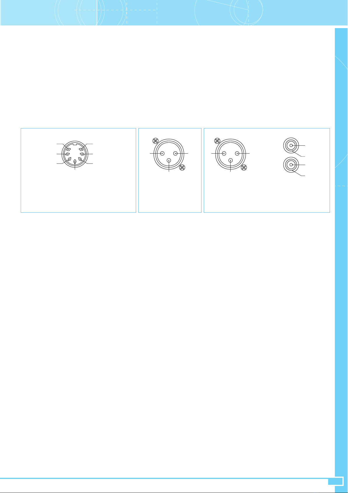
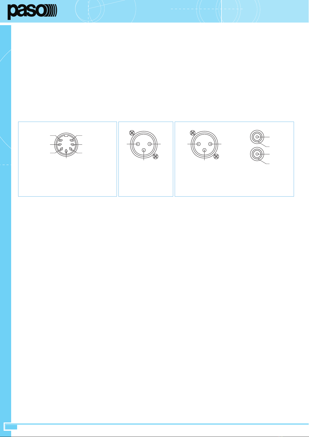
3.1 Entrée MIC.1
Cette entrée est disponible sur une prise à 7 contacts (20) dont le câblage
est décrit à la Fig. 1. La source d’entrée doit être de type équilibrée.
Important: les bornes de connexion du microphone fournissent la tension
d’alimentation ‘phantom’, par conséquent il n’est pas possible d’utiliser
des microphones de type non équilibré, en particulier de type dynamique.
La fermeture à la masse du contact “chime” active le signal de préavis et
l’assourdissement des entrées 2÷9 sur les canaux de sortie sélectionnés
pour le “chime”; la fermeture à la masse du contact “priority” ne produit
par contre que l’assourdissement des entrées 2÷9 sur les canaux de
sortie sélectionnés pour le microphone 1. La borne ‘Power Led’ fournit une
tension continue d’environ 14 V avec une résistance série de 1000 Ohms
pour certaines applications comme par exemple l’allumage d’une diode.
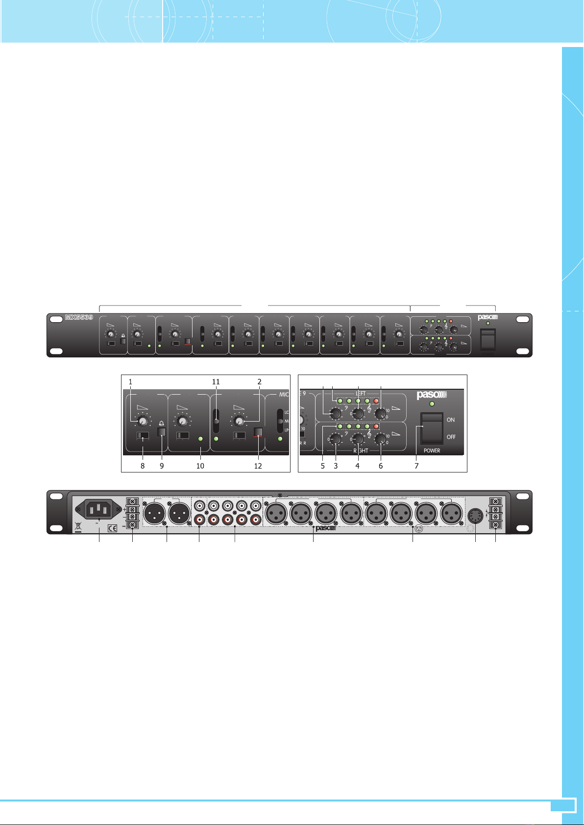
La façade présente un réglage individuel de niveau.
3.2 Entrées MIC/LINE 2 ÷ 5
Ces entrées sont disponible sur une prise de type XLR-F (19) pour des
signaux microphoniques et de ligne équilibrés dont le câblage est décrit
à la g. 2. La façade présente les sélecteurs individuels de modalité
(11) suivants:
• LCF sélectionne la sensibilité microphonique avec ltre voix activé
• MIC sélectionne la sensibilité microphonique avec ltre linéaire
• LINE sélectionne la sensibilité de ligne avec ltre linéaire
Important: les contacts des prises XLR-F sont pourvus d’une alimentation
‘Phantom’ et par conséquent il n’est pas possible d’utiliser des sources de
type non équilibré.
En appuyant sur la touche (12), il est activé la priorité automatique (VOX)
des entrées 2/3 sur les entrées 4 à 9 (sur les canaux de sortie sélectionnés
pour les entrées 2 et 3). La façade présente les réglages individuels de
niveau.
2.2 Speisung und Erdung
Das Gerät ist für den Betrieb mit einer Netzspannung 230 V ± 10%, 50/60
Hz ausgelegt. Alternativ ist der Betrieb mit externer Gleichspannung von
24V vorgesehen, die mit den entsprechenden Klemmen (14) angelegt wird.
Das Gerät wird mit einem Einspeisungskabel mit Erdleiter versehen und
das entsprechende Endstück am Netzstecker darf auf keinen Fall entfernt
werden. Stellen Sie sicher, dass die Steckdose einen Erdanschluss besitzt,
der den gesetzlichen Vorschriften entspricht.
2. HINWEISE
2.1 Sicherheitshinweise
Alle Geräte von Paso werden unter Einhaltung der strengsten
internationalen Sicherheitsauagen und unter Erfüllung der Auagen
der Europäischen Gemeinschaft gebaut. Für eine sachgemäße und
wirkungsvolle Anwendung des MX5539 ist es wichtig, alle seinen
Merkmale zu kennen und aus diesem Grund müssen die vorliegenden
Anleitungen und vor allem die Sicherheitshinweise sorgfältig gelesen
werden. Während des Betriebs muss eine angemessene Belüftung des
Geräts gewährleistet sein. Vermeiden Sie es, das Gerät MX5539 in einem
Möbel ohne Belüftung oder in der Nähe von Wärmequellen zu installieren
und es dem Kontakt mit Flüssigkeiten auszusetzen. Vor dem Einschalten
sicherstellen, dass alle Ein- und Ausgänge richtig angeschlossen sind. Das
Gerät ist für die Installation in einem Standard-Rack 19” ausgelegt.
Bei Entfernen der Geräteabdeckung besteht Stromschlaggefahr. Arbeiten
im Geräteinneren müssen von Fachpersonal ausgeführt werden. Vor dem
Auswechseln der Sicherungen sicherstellen, dass das Netzkabel und die
ggf. vorhandene sekundäre Speisung abgetrennt wurden. Immer mit
Sicherungen gleichen Typs und Werts auswechseln.
Niemals den Erdleiter vom Netzkabel entfernen. Um Stromschlaggefahr
oder Schäden zu vermeiden, keine Gegenstände, vor allem aus Metall,
durch die Geräteöffnungen einführen. Falls Flüssigkeiten in das Gerät
gelangen sollten, sofort den Netzstecker herausziehen und den nächsten
PASO-Kundendienst benachrichtigen.
WICHTIG!
Die Fa. PASO haftet nicht für Sach- und/oder Personenschäden, die aus
dem unsachgemäßen Gebrauch des Geräts oder aus nicht den Anleitungen
dieser Broschüre entsprechenden Verfahren resultieren.
3. ANSCHLÜSSE
3.1 Eingang MIC.1
Der Eingang liegt an einer Buchse mit 7 Kontakten (20), deren
Verkabelung in der Abbildung 1 beschrieben ist. Die Quelle am Eingang
muss symmetrisch sein. Wichtig: Die Anschlussendstücke des Mikrofons
liefern eine Phantom-Versorgungsspannung, so dass keine asymmetrischen
Mikrofone, insbesondere keine dynamischen Mikrofone verwendet werden
können. Das Schließen gegen Masse des Kontakts “Chime” führt zur
Aktivierung des Ankündigungssignals und zur Stummschaltung der Eingänge
2 ÷ 9 an den Ausgangskanälen, die für den Kontakt “Chime” ausgewählt
wurden, während das Schließen gegen Masse des Kontakts “Priority” zur
alleinigen Stummschaltung der Eingänge 2 ÷ 9 an den Ausgangskanälen
führt, die für das Mikrofon 1 ausgewählt wurden. Am Endstück ‘Power Led’
liegt eine Spannung von circa 14V GS mit einem Serienwiderstand von
1000 Ohm für Anwendungen wie bspw. das Leuchten einer LED. An der
Vorderseite bendet sich die individuelle Pegelregelung.
3.2 Eingänge MIC/LINE 2 ÷ 5
Die Eingänge liegen an einer Buche des Typs XLR-F (19) für
Mikrofonsignale und die symmetrische Leitung, deren Verkabelung in der
Abb. 2 beschrieben ist. An der Vorderseite benden sich die einzelnen
Moduswahlschalter (11):
• LCF wählt die Mikrofonempndlichkeit mit aktiviertem Sprachlter aus
• MIC wählt die Mikrofonempndlichkeit mit linearem Filter aus
• LINE wählt die Leitungsempndlichkeit mit linearem Filter aus
Wichtig: An den Kontakten der Buchsen XLR-F liegt die ‘Phantom-Speisung’,
so dass keine asymmetrischen Quellen verwendet werden können.
Bei Gedrückthalten der Taste (12) wird der automatische Vorrang (VOX) der
Eingänge 2/3 an den Eingängen 4 bis 9 aktiviert (an den Ausgangskanälen,
die für die Eingänge 2 und 3 ausgewählt wurden). An der Vorderseite
benden sich die einzelnen Pegelegler.